Table of Contents
Advertisement
Quick Links
Advertisement
Table of Contents

Related Manuals for Jireh ROTIX


Summary of Contents for Jireh ROTIX
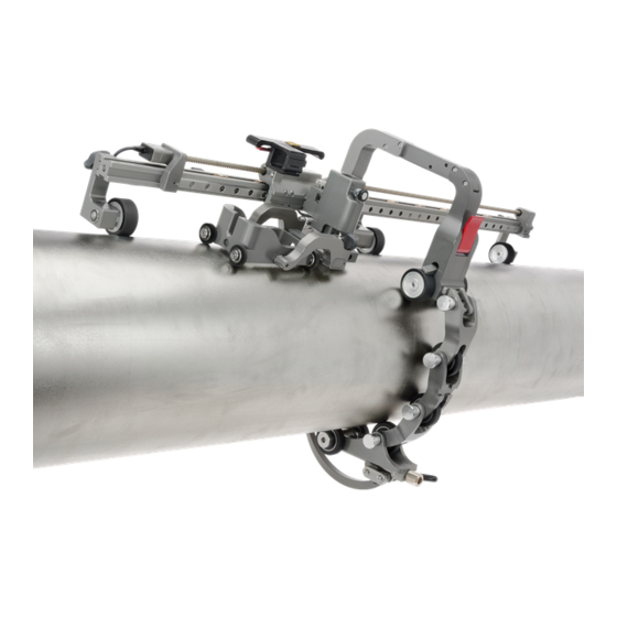
- Page 1 ROTIX CE0160 Rev 03 3-Axis Nozzle Scanner...
- Page 2 SAFETY WARNINGS / PRECAUTIONS KEEP THIS MANUAL – DO NOT LOSE THIS MANUAL IS PART OF THE ROTIX AND MUST BE RETAINED FOR THE LIFE OF THE PRODUCT. PASS ON TO SUBSEQUENT OWNERS. Ensure any amendments are incorporated with this document.
-
Page 3: Table Of Contents
4.1.2. Encoded Skew Vertical Probe Holder 4.1.3. Frame Bar with Ruler 4.1.4. Slider PPS Encoder 4.1.5. Slider Probe Positioning System 4.1.6. ROTIX - Short Link 4.1.7. ROTIX - Short Link with Dovetail 4.1.8. ROTIX - Long Link 4.1.9. ROTIX - Buckle 4.1.10. ROTIX - Catch Link 4.1.11. J400 Encoder Cable 4.1.12. Cable Management, Dovetail Mount... - Page 4 4.2.2. Encoded Skew Vertical Probe Holder 4.2.3. Frame Bar with Ruler 4.2.4. Slider PPS Encoder 4.2.5. Slider Probe Positioning System 4.2.6. High Temperature Short Link 4.2.7. High Temperature Dovetail Link 4.2.8. High Temperature Long Link 4.2.9. High Temperature Buckle 4.2.10. High Temperature Catch Link 4.2.11. Short Transition Link 4.2.12. J400 Encoder Cable 4.2.13. High Temperature Cable Management 4.2.14. Irrigation Kit 4.2.15. Tools...
- Page 5 Operation Chapter 6.1. Setup of ROTIX on Scanning Surface 6.2. Using a Slider Probe Positioning System Maintenance Chapter Troubleshooting Chapter 8.1. Technical Support Service and Repair Chapter Spare Parts Chapter 10.1. Low Profile Link 10.2. Kit Components 10.2.1. Encoder Connector Type 10.2.2. Probe Positioning...
-
Page 6: Product Brand
Chapter 1 IDENTIFICATION 1.1. Product Brand This user manual describes the proper safety precautions, setup and use of the ROTIX - Nozzle Scanner. 1.2. Manufacturer Distributor: Manufacturer: Jireh Industries Ltd. 53158 Range Road 224 Ardrossan, Alberta, Canada T8E 2K4 Phone: 780.922.4534 jireh.com... -
Page 7: Product Specifications
(3 in) Maximum nozzle range 60 cm (24 in) 2.1.1.2 Operating Environment The ROTIX chain scanner is designed for use in an industrial environment that is between -20° C and 50° C (-4° F) (122° F) The ROTIX - High Temperature Kit is required for surface temperatures between 50°C - 350°C... - Page 8 Fig. 1 - Low profile link dimensions Fig. 2 - Encoded skew vertical probe holder dimensions Rev. CE0160 Rev 03 PAGE 3 of 55...
-
Page 9: Environmental Sealing
2.2.1. Environmental Sealing Dust-tight, watertight (not submersible) 2.2.2. Performance Specifications X-Axis encoder resolution 16.3 counts/mm (414.5 counts/inch) Y-Axis encoder resolution 161.3 counts/mm (slider PPS) (4096.0 counts/inch) Skew encoder resolution 2.84 counts/deg PAGE 4 of 55... -
Page 10: Definitions
Chapter 3 DEFINITIONS 3.1. Definitions of Symbols Instructions to ‘look here’ or to ‘see this part.’ Denotes movement. Instructing users to carry out action in a specified direction. Indicates alignment axis Alerts user that the view has changed to a reverse angle. 3.2. -
Page 11: System Components
Chapter 4 SYSTEM COMPONENTS 4.1. Base System Components 4.1.1. Low Profile Link CEA024 The low profile link contains the main positional encoder and a mounting point for a frame bar. Two encoder inputs are located at the rear of the link, along with the output to the user’s instrument (Fig. -
Page 12: Frame Bar With Ruler
4.1.3. Frame Bar with Ruler BG0090- The frame bar with ruler (Fig. 6) is used to mount probe holders, probe positioning systems and other accessories. Metric measurements are included on the frame bar. Frame bars are available in a variety of lengths. Fig. -
Page 13: Rotix - Short Link
(Fig. 9) Fig. 9 - Short link 4.1.7. ROTIX - Short Link with Dovetail CES024 Similar to a standard ROTIX - Short Link but with the addition of a dovetail for mounting optional accessories (Fig. -
Page 14: Rotix - Buckle
(Fig. 12) Fig. 12 - Buckle 4.1.10. ROTIX - Catch Link CES003 The ROTIX - catch link is used with the ROTIX - buckle to clamp a single wheel chain scanner to an inspection surface. The dovetail mount of the catch... -
Page 15: Cable Management, Dovetail Mount
4.1.12. Cable Management, Dovetail Mount CES044- Cable management provides a means of protecting and organizing cables, tubes and hoses (Fig. 15) Fig. 15 - Cable Management, Dovetail Mount 4.1.13. Irrigation Kit CMG007 The irrigation kit provides a variety of hoses, fittings, connectors, and splitters commonly used during non- destructive inspection... -
Page 16: Base High Temperature Components
4.2. Base High Temperature Components 4.2.1. High Temperature Low Profile Link CEA031 The low profile link contains the main positional encoder and a mounting point for a frame bar. Two encoder inputs are located at the rear of the link, along with the output to the user’s instrument (Fig. -
Page 17: Frame Bar With Ruler
4.2.3. Frame Bar with Ruler BG0090- The frame bar with ruler (Fig. 19) is used to mount probe holders, probe positioning systems and other accessories. Metric measurements are included on the frame bar. Frame bars are available in a variety of lengths. Fig. -
Page 18: High Temperature Short Link
4.2.8. High Temperature Long Link CES075 The long link is roughly equivalent to the length of three ROTIX - Short Links and is used to assemble various lengths of single wheel chain configurations (Fig. 24) Fig. 24 - High temperature long link Rev. -
Page 19: High Temperature Buckle
(Fig. 25) Fig. 25 - High temperature buckle 4.2.10. High Temperature Catch Link CES077 The ROTIX - catch link is used with the ROTIX - buckle to clamp a single wheel chain scanner to an inspection surface. The dovetail mount of the catch... -
Page 20: J400 Encoder Cable
4.2.12. J400 Encoder Cable UMA036- The encoder cable connects the ROTIX system to the user’s instrument. (Fig. 28) Various encoder cable styles are available for various instruments. NOTE: Inspect the cable and connectors for damage before use. When damage is evident, the - J400 Encoder cable Fig. -
Page 21: Tools
Fig. 32 - 3/8 in wrench The 3 mm hex driver is sufficient for all typical operations and (Fig. 31) adjustments of the ROTIX. The 3/8 in wrench is used to remove and install pivot buttons on the (Fig. 32) probe holders. -
Page 22: Preparation For Use
Chapter 5 PREPARATION FOR USE 5.1. Configurations 5.1.1. Nozzle Scanner Fig. 33 - Nozzle scanner configuration laid out flat Fig. 34 - Nozzle scanner configuration Rev. CE0160 Rev 03 PAGE 17 of 55... -
Page 23: High Temperature Nozzle Scanner
5.1.2. High Temperature Nozzle Scanner Fig. 35 - High temperature nozzle scanner configuration laid out flat Fig. 36 - High temperature nozzle scanner configuration PAGE 18 of 55... -
Page 24: Low Profile Link Adjustment And Setup
5.2. Low Profile Link Adjustment and Setup Fig. 37 - ROTIX - Low profile link 5.2.1. Brake The red lever operates the brake. Lower the lever to activate the brake and prevent scanner movement. Raise the lever to disengage the brake (Fig. -
Page 25: Frame Bar Attachment
5.2.2. Frame Bar Attachment Rotate the two knobs at the front of the low profile link to align the dovetail jaws (Fig. 39). Slide the frame bar over the two dovetails of the low profile link (Fig. 40) Tighten the two knobs to secure the frame bar in place (Fig. -
Page 26: Cable Clip
5.2.4. Cable Clip Fig. 44 - Cable clip mounting points Fig. 45 - Pinch clip and press into place Locations for cable clips have been provided to assist with cable management . To route the cable or hose through the cable clips, place the cable clip (Fig. -
Page 27: Encoded Skew Vertical Probe Holder
5.3. Encoded Skew Vertical Probe Holder Probe Holder Adjustment Knob Probe Holder Arms Pivot Buttons Encoder Cable Skew Adjustment Indicator Ratchet Lever Latch Pin Cable Clip Probe Holder Arm Adjustment Knob Fig. 46 - Encoded skew vertical probe holder identification PAGE 22 of 55... -
Page 28: Probe Holder Setup
5.3.1. Probe Holder Setup Using the supplied 3/8 in wrench (Fig. 32), install the appropriate pivot buttons to the probe holder arms (Fig. 47) Fig. 47 - Attach pivot buttons Fig. 48 - Mount to slider pps Fig. 49 - Mount to slider pps Loosen the probe holder adjustment knob to attach the encoded skew vertical probe holder to the slider pps slider (Fig. - Page 29 To mount a UT wedge in the probe holder, follow these steps: Fig. 50 - Loosen knobs and move arms Fig. 51 - Align probe Loosen the two probe holder arm adjustment knobs and move the arms apart to create space for the probe (Fig.
-
Page 30: Encoded Skew Vertical Probe Holder Adjustment
Fig. 53 - Clamp probe with arms and tighten knobs Route the skew encoder cable through the required cable clips (Fig. 53). Plug the skew encoder cable into ENC 2 at the rear of the low profile link (Fig. 53) 5.3.2. - Page 31 Pull the latch pin (Fig. 55) and slowly lower the probe holder to the scan surface (Fig. 56) TIP: The probe holder must be lifted slightly to pull and release the latch pin. Fig. 56 - Lower probe to inspection surface 5.3.2.3 Latch Pin The latch pin may be used in one of two methods:...
-
Page 32: Skew Angle Adjustment
5.3.3. Skew Angle Adjustment Rotation of the probe holder is possible through adjustment of the skew angle. Fig. 59 - Loosen ratchet lever Fig. 60 - Adjust skew angle Loosen the ratchet lever above the yoke (Fig. 59) Rotate the yoke to the angle required (Up to 90°... -
Page 33: Pivot Buttons
Fig. 63 - Rotate handle Fig. 64 - Tighten handle The rachet levers are used for various locking functions on the ROTIX system. Occasionally, movement of the lever locking position is required. The lever placement can be adjusted by following these steps: Pull the ratchet lever away from the base to which it is connected (Fig. -
Page 34: Slider Pps
5.4. Slider PPS (Slider Probe Positioning System) The slider PPS uses a slide and leadscrew system to manipulate the position of a probe along a frame bar. To set up and install a slider PPS, follow these steps: Fig. 66 - Place slider on frame bar and loosen slider lock knob Ease the slider onto the frame bar and push it into position . - Page 35 Fig. 68 - Insert leadscrew into main knob and slider Rotate the leadscrew to insert it into the main knob and slider (Fig. 68) Fig. 69 - Tighten screws Position the slider and main knob where required along the frame bar. Tighten the main knob’s hexagonal screw and lock screw, and tighten the slider lock knob (Fig.
-
Page 36: Slider Pps Encoder
5.4.1. Slider PPS Encoder The slider PPS encoder provides positional feedback (probe positioning system) perpendicular to the scan direction of travel. Follow these steps for installation: Ensure the encoder’s lock screw is loose. Fig. 70 - Loosen and slide post in place Fig. -
Page 37: Chain Components
5.5. Chain Components The chain components fasten a nozzle scanning system circumferentially around a pipe or tube. Fig. 73 - Short link Fig. 75 - Short link with dovetail Fig. 74 - Catch link Fig. 77 - Buckle Fig. 76 - Long link 5.5.1. -
Page 38: Cable Management System
5.6. Cable Management System Fig. 81 - Cable management TIP: When using cable management, ensure the dovetail link is placed 2 in the chain behind the low profile link. 5.6.1. Cable Management Dovetail Mount To attach the cable management, follow these steps: Fig. -
Page 39: Cable Management Setup
5.6.2. Cable Management Setup Cable management is available in a variety of lengths and provides a means of bundling and protecting cables and hoses that run to a scanner. Fig. 84 - Insert cables and hoses Fig. 85 - Zip up to close Open the zipper of the cable management. -
Page 40: Clamp Setup
5.6.3. Clamp Setup If the sleeving becomes disconnected from the cable management dovetail mount, follow these instructions to re-attach the sleeving and dovetail mount. Loosen the clamp screw using the supplied 3 mm hex driver. Fig. 88 - Slide tube around mount Slide the clamp around the sleeving first and then slide the sleeving around the outside of the... -
Page 41: Cable Clip
5.7. Cable Clip Cable clips have been provided to assist with cable management. Pinch the clip and press it into the dovetail groove of the frame bar or the probe holder. Fig. 91 - Pinch clip Fig. 93 - Route cables Fig. -
Page 42: Operation
Fig. 94 - Refer to setup chart Fig. 95 - Assemble configuration Determine the diameter of the nozzle to be scanned. The ROTIX kit includes a setup chart indicating the number of links required based on the pipe diameter or tubing (Fig. - Page 43 On a flat surface, connect the appropriate amount of links as indicated on the ROTIX setup chart. Arrange the link setup so the buckle and catch link will be 180° opposite the low profile link (Fig. 96) TIP: Place the dovetail link 2 in the chain behind the low profile link (Fig.
- Page 44 (Fig. . The tightness of the 99-3) ROTIX on the pipe can be adjusted using the buckle adjustment knob (Fig. 99-A) TIP: If additional Fig. 99 - Adjust pressure of buckle...
- Page 45 Fig. 101 - Lower probe holder to scan surface Pull the probe holder latch pin to release the probe holder from the (Fig. 101-A) locked position (see Latch Pin on page 26 for more information) Lower the probe to the scan surface (see Encoded Skew Vertical Probe Holder Adjustment on page 25).
-
Page 46: Using A Slider Probe Positioning System
6.2. Using a Slider Probe Positioning System (Slider PPS) To set up and install a slider probe positioning system (see Slider PPS on page 29). Ensure the slider lock knob (Fig. 103-A) is tight and rotate the main knob to position the slider (Fig. -
Page 47: Maintenance
Chapter 7 MAINTENANCE General cleaning of components is important to keep your system working well. All components that have no wiring or cables are completely waterproof. Components can be washed with warm water, dish soap and a medium bristle brush. After washing your system, use a light oil to lubricate the slide and the adjustment screw on the buckle component . -
Page 48: Troubleshooting
Chapter 8 TROUBLESHOOTING Problem Possible Cause Solution Chain is too Incorrect number or Refer to the ROTIX setup chart (see on loose/tight. combination of links for required number of links page 6) for proper scanner for the diameter of pipe/tube that is to be configuration. -
Page 49: Service And Repair
Chapter 9 SERVICE AND REPAIR WARNING! DO NOT DISASSEMBLE. No user-serviceable parts. Disassembling any of the components in this product, beyond the instructions in this user manual, could void the regulatory certifications and/or effect the safety of the product. PAGE 44 of 55... -
Page 50: Spare Parts
Chapter 10 SPARE PARTS To order accessories or replacement parts for your ROTIX system. (contact Jireh Industries Ltd. on page 1) NOTE: These drawings are for parts order. This is not a list of kit contents. 10.1. Low Profile Link... -
Page 51: Kit Components
CES002 Short Link EA470 Wrench UMA036-X-05 J400 Encoder Cable, 5 m (16.4 ft) (see Encoder Connector Type) CEG039 ROTIX - Nozzle Spare Parts Kit BG0090-X Frame Bar with Ruler, 30 cm EA414 Hex Driver PAGE 46 of 55 CES005 Buckle... -
Page 52: Encoder Connector Type
Description CES002 Short Link EA470 Wrench UMA036-X-05 J400 Encoder Cable, 5 m (16.4 ft) (see Encoder Connector Type) CEG039 ROTIX - Nozzle Spare Parts Kit BG0090-X Frame Bar with Ruler, 30 cm EA414 Hex Driver CES005 Buckle CE0015 Ratchet Lever MD073-025 BHCS, M4x0.7 X 25... -
Page 53: Probe Positioning
Fig. 107 - Slider probe positioning system parts TD - Focus Scan, Handy Scan, Pocket Scan Pragma PAUT 16/128, PragmaLite / Pragma UT400 NOTE: Additional leadscrew lengths are available. (contact Jireh Industries Ltd. on page 1) Length Swing Arm Style Part #... -
Page 54: Encoded Skew Vertical Probe Holder
10.3. Encoded Skew Vertical Probe Holder BOM ID Part # Description BG0091 Cable Clip PH0082 Knurled Knob, M4 x 0.7 x 10 , SST, 3 mm stand off, PH0011-X see Pivot Button Style PH0237 Nozzle, Extra Short Arm Style: PHS069 Encoded Skew Vertical Probe Holder Subassembly PHS068 Encoded Skew Vertical Probe Holder Slide... -
Page 55: Probe Holder Components
NOTE: Additional probe holder pivot button types are available. Part # Length Part # Length TD - Focus Scan, Handy Scan, Pocket Scan Pragma PAUT 16/128, PragmaLite / Pragma UT400 (contact Jireh Industries Ltd. on page 1) BG0038-05 (1.97 BG0038-10 (3.94 BG0038-15 BG0038-20 (5.91... -
Page 56: Accessories
10.6. Accessories 10.6.1. Cable Management BOM ID Part # Description CES067 Cable Management Mount CES066 Cable Management Clamp see Cable Management Sleeving Fig. 112 - Cable management 10.6.1.1 Cable Management Sleeving Part # Length CX0141 4.5 m (14.7 ft) CX0145 9.5 m (31.1 ft) Fig. -
Page 57: Disposal
Electronic Equipment (WEEE), this symbol indicates that the product must not be disposed of as unsorted municipal waste, but should be collected separately. Refer to Jireh Industries for return and/or collection systems available in your country. PAGE 52 of 55... -
Page 58: Limited Warranty
THREE (3) YEARS from the original date of purchase. If a defect exists, at its option Jireh will (1) repair the product at no charge, using new or refurbished replacement parts, (2) exchange the product with a product that is new... -
Page 59: Appendix
Changes or modifications to this unit or accessories not expressly approved by the party responsible for compliance could void the user’s authority to operate the equipment. All specifications are subject to change without notice. © 2017 - 2023 JIREH Industries Ltd. PAGE 54 of 55... -
Page 60: Chain Configuration Setup Chart
13.1. Chain Configuration Setup Chart PIPE SIZE LINKS LONG SHORT (in) (in) (mm) (mm) 10.0 10.2 10.2 11.0 10.9 11.8 11.7 12.6 12.6 13.5 13.5 14.4 14.4 15.2 15.1 16.0 15.9 16.8 16.7 17.5 17.5 18.4 18.3 19.1 19.0 19.9 19.9 20.8 20.7... - Page 61 Jireh Industries Ltd. 53158 Range Road 224 Ardrossan, Alberta Canada T8E 2K4 780-922-4534 jireh.com...
Need help?
Do you have a question about the ROTIX and is the answer not in the manual?
Questions and answers