Table of Contents
Advertisement
Quick Links
Advertisement
Table of Contents

Related Manuals for Jireh ROTIX


Summary of Contents for Jireh ROTIX
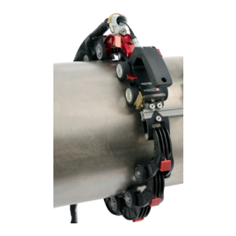
- Page 1 ROTIX CE0189 Rev 00 Manual Chain Scanner...
- Page 2 SAFETY WARNINGS / PRECAUTIONS KEEP THIS MANUAL – DO NOT LOSE THIS MANUAL IS PART OF THE ROTIX AND MUST BE RETAINED FOR THE LIFE OF THE PRODUCT. PASS ON TO SUBSEQUENT OWNERS. Ensure any amendments are incorporated with this document.
-
Page 3: Table Of Contents
TABLE OF CONTENTS Identification Chapter 1.1. Product Brand 1.2. Manufacturer Product Specifications Chapter 2.1. Base ROTIX Specifications 2.1.1. Intended Use 2.1.2. Dimensions and Weight 2.1.3. Environmental Sealing 2.1.4. Performance Specifications Definitions Chapter 3.1. Definition of Symbols 3.2. Definitions of Terms System Components Chapter 4.1. Base System Components 4.1.1. Cart Body... - Page 4 4.2.1. Frame Bar 4.2.2. Vertical Probe Holder 4.2.3. Probe Positioning System (PPS) 4.2.4. PPS Encoder 4.2.5. Slider Probe Positioning System (Slider PPS) 4.2.6. Slider PPS Encoder 4.2.7. Crank Handle 4.2.8. Encoder Adapter 4.2.9. Preamp Bracket 4.2.10. Reduced Width Scanning Kit 4.3. Tools 4.3.1. Included tools 4.3.2. Optional tools Preparation for Use Chapter 5.1.
- Page 5 5.14.1. Mounting Preamp Bracket 5.14.2. Attaching Preamp with Screws 5.14.3. Attaching Preamp with Velcro Straps Operation Chapter 6.1. Setup of ROTIX on Scanning Surface 6.2. Using a Probe Positioning System (PPS) 6.3. Using a Slider Probe Positioning System (Slider PPS) Maintenance Chapter PAGE iv of v...
- Page 6 Troubleshooting Chapter 8.1. Technical Support Service and Repair Chapter Spare Parts Chapter 10.1. ROTIX Cart 10.2. Kit Components 10.2.1. Encoder Connector Type 10.2.2. Stabilizer Wheel 10.3. Probe Positioning 10.3.1. Probe Positioning System (PPS) 10.3.2. Slider Probe Positioning System (Slider PPS) 10.3.3. Slider PPS Encoded Leadscrew 10.4.
-
Page 7: Identification
Chapter 1 IDENTIFICATION 1.1. Product Brand This user manual describes the proper safety precautions, setup and use of the ROTIX scanner. 1.2. Manufacturer Distributor: Manufacturer: Jireh Industries Ltd. 53158 Range Road 224 Ardrossan, Alberta, Canada T8E 2K4 780.922.4534 jireh.com Rev. CE0189 Rev 00... -
Page 8: Product Specifications
Maximum OD, external 96.5 cm (38 in) circumferential pipe/tube range 2.1.1.2 Operating Environment The ROTIX scanner is designed for use in an industrial environment that is between -20° C and 50° C (-4° (122° 2.1.2. Dimensions and Weight - Cart dimensions Fig. -
Page 9: Environmental Sealing
(3.9 in) (Fig. 1-3) Cart weight 0.67 kg (1.48 lb) 2.1.3. Environmental Sealing Watertight (submersible) (contact Jireh Industries Ltd. on page 1 for details) 2.1.4. Performance Specifications Category Specification X-Axis encoder resolution 66.0 counts/mm ( 1676.3 counts/inch) Y-Axis encoder resolution 40.3 counts/mm... -
Page 10: Definitions
Chapter 3 DEFINITIONS 3.1. Definition of Symbols Instructions to ‘look here’ or to ‘see this part.’ Denotes movement. Instructing the user to carry out an action in a specified direction. Indicates alignment axis, can also indicate insertion or movement of parts. Alerts user that the view has changed to a reverse angle. -
Page 11: System Components
Chapter 4 SYSTEM COMPONENTS 4.1. Base System Components 4.1.1. Cart Body CEA034 The cart body houses the positional encoder and provides a pivot nose for mounting frame bars and probe holders. The encoder connector is located at the rear of the cart, while the auxiliary connector is found under the handle (Fig. -
Page 12: Quicklink Components
4.1.4. QuickLink Components The QuickLink components fasten a ROTIX system circumferentially around a pipe or tube. 4.1.4.1 QuickLink ESS004 QuickLinks connect to assemble the required length to mount the system on a pipe (Fig. 6) - QuickLink Fig. 6 4.1.4.2 Dovetail QuickLink... -
Page 13: Stabilizer Wheel
(Fig. 10) - Stabilizer wheel Fig. 10 4.1.6. J100 Encoder Cable UMA026- The encoder cable connects the ROTIX system to the user’s instrument. (Fig. 11) Various encoder cable styles are available for various instruments. NOTE: Inspect the cable and connectors for damage before use. -
Page 14: Cable Management, Dovetail Mount
4.1.7. Cable Management, Dovetail Mount CES044- Cable management provides a means of protecting and organizing cables, tubes and hoses (Fig. 12) - Cable management, dovetail mount Fig. 12 4.1.8. Irrigation Kit CMG007 The irrigation kit provides a variety of hoses, fittings, connectors, and splitters commonly used during non-destructive inspection (Fig. -
Page 15: Compatible Components
4.2. Compatible Components 4.2.1. Frame Bar BG0038- Frame bars are used to (Fig. 14) mount probe holders, probe positioning systems and other accessories. Frame bars are available in a variety of lengths. - Frame bar Fig. 14 4.2.2. Vertical Probe Holder PHA015- The vertical probe holder is designed to carry many different... -
Page 16: Pps Encoder
4.2.4. PPS Encoder DKS009- Enable two-axis encoding with ROTIX scanners (Fig. 17) - PPS encoder Fig. 17 4.2.5. Slider Probe Positioning System (Slider PPS) CJS016 The slider probe positioning system sets the probe centre spacing and allows an operator to... -
Page 17: Crank Handle
4.2.7. Crank Handle CJS016 The crank handle mounts to a slider probe positioning system to allow for quick and easy adjustment of probe positioning (Fig. 20) - Crank handle Fig. 20 4.2.8. Encoder Adapter UMA010- Adapt a scanner’s existing encoder connector to a different encoder style (Fig. -
Page 18: Reduced Width Scanning Kit
Fig. 24 Fig. 25 The 3 mm hex driver is sufficient for all typical operations and adjustments (Fig. 24) of the ROTIX. The 3/8 in wrench removes and installs buttons on the probe holders. (Fig. 25) 4.3.2. Optional tools Some specialized adjustments require tools that are not included in this kit. -
Page 19: Preparation For Use
Chapter 5 PREPARATION FOR USE 5.1. Configurations 5.1.1. One Probe, Single Axis Encoding - One probe, single axis encoding Fig. 30 5.1.2. Two Probe, 1 Axis Encoding - Two probe, 1 axis encoding Fig. 31 Rev. CE0189 Rev 00 PAGE 13 of 77... -
Page 20: Four Probe, Two-Axis Encoding
5.1.3. Four Probe, Two-Axis Encoding - Four probe, two-axis encoding Fig. 32 5.1.4. Single Probe, Two-Axis Encoding with Single PPS (Probe Positioning System) - Single probe, two-axis encoding with single PPS Fig. 33 PAGE 14 of 77... -
Page 21: Two Probe, Two-Axis Encoding With Pps
5.1.5. Two Probe, Two-Axis Encoding with PPS (Probe Positioning System) - Two probe, two-axis encoding with PPS Fig. 34 5.1.6. Four Probe, Two-Axis Encoding with PPS (Probe Positioning System) - Four probe, two-axis encoding with PPS Fig. 35 Rev. CE0189 Rev 00 PAGE 15 of 77... -
Page 22: Single Probe, Two-Axis Encoding With Slider Pps
5.1.7. Single Probe, Two-Axis Encoding with Slider PPS (Probe Positioning System) - Single probe, two-axis encoding with slider PPS Fig. 36 5.1.8. Two Probe, Two-Axis Encoding with Slider PPS (Probe Positioning System) - Two probe, two-axis encoding with slider PPS Fig. -
Page 23: Cart Setup And Adjustment
5.2. Cart Setup And Adjustment 5.2.1. Cart Handle The handle provides an ergonomic grip during use. The cart handle may be removed using the supplied 3 mm hex driver to achieve a lower profile when required (Fig. 38) - Cart handle Fig. -
Page 24: Wheel Removal/Installation
5.2.3. Wheel Removal/Installation Urethane wheels provide smooth rolling and are to be used with QuickLinks. The wheels of this system may be removed and are interchangeable. To remove/install the wheels, insert the provided 3 mm hex driver in the shaft of the wheel you wish to remove. -
Page 25: Auxiliary Connector
5.2.5. Auxiliary Connector The auxiliary connector provides a connection point for optional accessories, such as PPS encoders that provide positional feedback perpendicular to the direction of cart travel. The auxiliary connector is found under the cart handle (Fig. 43) - Auxiliary connector Fig. -
Page 26: Cable Management
Mount the frame bar on the dovetail jaw of the pivot mount and tighten the knobs (Fig. 45) The angle of the frame bar should be adjusted to match the angle of the inspection surface (see instruction 6 on page 51 for additional details) - Pivot Fig. -
Page 27: Anchor Point
- Open clip and place cables and hoses - Close clip and twist latch to lock Fig. 49 Fig. 50 Open the cable management clip and place cables and hoses in the clip as required (Fig. 49). Twist to latch to lock the cable management clip closed (Fig. -
Page 28: Quicklink Mounting Bracket
5.2.10. QuickLink Mounting Bracket The QuickLink Mounting Bracket provides a connection for the QuickLinks. - QuickLink Mounting Bracket - QuickLink mount alignment Fig. 53 Fig. 54 Secure the QuickLink Mounting Bracket to the frame bar by tightening the knob (Fig. 53) Centre the QuickLink Mounting Bracket to the centre point marking on the cart’s pivot mount (Fig. -
Page 29: Disconnecting Quicklinks
5.3.2. Disconnecting QuickLinks To disconnect QuickLinks, see the following steps: - Press button - Slide QuickLink forward and lift Fig. 57 Fig. 58 Press the button on the top of the QuickLink (Fig. 57) 2. While pressing the button, slide the QuickLink forward and up, clearing the hook of the QuickLink from the 2 QuickLink’s axle (Fig. -
Page 30: Stabilizer Wheel
5.4. Stabilizer Wheel The stabilizer wheel is used to balance the frame bar and to keep the frame bar parallel to the inspection surface. WARNING! MAGNETIC MATERIAL. The stabilizer wheel uses a magnetic wheel. People with pacemakers or ICD’s must stay at least 25 cm (10 in) away. -
Page 31: Ratchet Lever
Fig. 64 Fig. 65 Fig. 66 The rachet levers are used for various locking functions on the ROTIX system. Occasionally, movement of the lever locking position is required. The lever placement can be adjusted by following these steps: Pull the ratchet lever away from the base to which it is connected (Fig. -
Page 32: Probe Positioning System (Pps)
5.5. Probe Positioning System (PPS) The probe positioning system uses a linear rail and leadscrew system to position (PPS) two or four probes for weld inspection. Used to adjust probe-to-probe spacing and allow the operator to center probes over the weld without removing the scanner. To operate a probe positioning system (see Using a Probe Positioning System (PPS) on page 5.5.1. -
Page 33: Four Probe Setup
- Tighten dovetail nuts along linear rail Fig. 69 TIP: In most applications, mounting the frame bar flush with the knob side of the PPS is recommended. 5.5.2. Four Probe Setup It is possible to increase the probe holding capabilities of the probe positioning system to a four probe setup. -
Page 34: Index Encoding
5.5.3. Index Encoding The index encoder provides positional feedback perpendicular to the scan direction of travel. - Loosen and slide post in place - Align and mount post Fig. 71 Fig. 72 To install the index encoder, loosen the clamp screw of the index encoder support bracket with the supplied 3 mm hex driver (Fig. -
Page 35: Slip Joint Probe Holder
5.6. Slip Joint Probe Holder Frame Bar Probe Holder Adjustment Knob Latch Swing Arm Knob Yoke Probe Holder Arm Adjustment Knob Probe Holder Arm Arm Clamp Screw Pivot Buttons - Slip Joint Probe Holder Fig. 75 5.6.1. Probe Holder Setup To mount a UT wedge in the probe holder, follow these steps: - Adjust on frame bar - Attach to frame bar... - Page 36 3. Use swing arm knob to position the swing arm (Fig. 78). TIP: The swing arm is typically used to adjust TOFD center-to-center distance relative to the phased array probes on a four probe configuration (Fig. 35). 4. Using the supplied 3/8 in wrench , place the pivot buttons as required (Fig.
-
Page 37: Probe Holder Adjustment
5.6.2. Probe Holder Adjustment To adjust the probe holder, follow these steps: 6 mm approx. - Lift to Latched position - Lower to scanning surface Fig. 83 Fig. 84 Ensure the probe holder is in latched, upper position . If the probe (Fig. - Page 38 To adjust the probe holder’s force, follow these steps: NOTE: Do not perform this operation on a scanning surface. - Lift slightly and press latch - Unlatched position Fig. 87 Fig. 88 Ensure the probe holder is in the upright latched position (Fig.
-
Page 39: Slip Joint Probe Holder Left/Right Conversion
5.6.4. Slip Joint Probe Holder Left/Right Conversion To reverse the probe holder, follow these steps: - Unscrew yoke pivot screw - Remove arms Fig. 92 Fig. 93 Unscrew the yoke from the swing arm (Fig. 92) 2. Loosen the probe holder arm adjustment knob and arm clamp screw. Slide the arms from the yoke (Fig. -
Page 40: Pivot Buttons
- Install yoke to swing arm - Position swing arm Fig. 97 Fig. 96 5. Loosen the swing arm knob and slide the swing arm to the opposite end of the probe holder bracket or the preferred position. Tighten the swing (Fig. -
Page 41: Cable Management System
5.7. Cable Management System - Cable management Fig. 100 The cable management provides a means of bundling and protecting cables and hoses that connect to the scanner. 5.7.1. Cable Management Dovetail Mount To attach cable management, follow these steps: - Loosen and slide on - Tighten knob Fig. -
Page 42: Cable Management Setup
5.7.2. Cable Management Setup Cable management is available in a variety of lengths and provides a means of bundling and protecting cables and hoses that run to a scanner. - Insert cables and hoses - Zip up to close Fig. 103 Fig. -
Page 43: Clamp Setup
5.7.3. Clamp Setup If the tube becomes disconnected from the cable management dovetail mount, follow these instructions to re-attach the tube and dovetail mount. Loosen the clamp screw using the supplied 3 mm hex driver. - Slide tube around mount Fig. -
Page 44: Vertical Probe Holder
5.9. Vertical Probe Holder Latch Probe Holder Adjustment Knob Vertical Adjustment Knob Pivot Buttons Probe Holder Arms Yoke Probe Holder Arm Adjustment Knob Transverse Adjustment Screw Frame Bar - Vertical probe holder Fig. 111 5.9.1. Probe Holder Setup - Adjust on frame bar - Vertical adjustment - Place buttons Fig. -
Page 45: Probe Holder Vertical Adjustment
To mount a UT wedge in the probe holder, follow these steps - Adjust inner arm - Adjust outer arm - Tighten arm knob Fig. 115 Fig. 116 Fig. 117 4. Position the wedge on the inner probe holder arm. TIP: The probe holder yoke can accommodate many different probe and wedge sizes of varying widths. -
Page 46: Probe Holder Transverse Adjustment
Ensure the probe holder is in the latched upper position. Do this by lifting the probe holder till the latch is fully exposed (Fig. 118) 2. Loosen the vertical adjustment knob and slide the probe holder down until the wedge is approximately 6 mm (¼ in) above inspection surface (Fig. -
Page 47: Probe Holder Longitudinal Adjustment
Ensure the probe holder is in latched upper position (Fig. 118) 2. Using the supplied 3 mm hex driver loosen the transverse adjustment screw and rotate the yoke about the vertical shaft achieving the desired (Fig. 122) angle. 3. Tighten the transverse adjustment screw (Fig. -
Page 48: Probe Holder Left/Right Conversion
5.9.5. Probe Holder Left/Right Conversion To reverse the probe holder, follow these steps: NOTE: The 1.5 mm hex wrench (Fig. 26) is required to perform this operation. - Unscrew yoke pivot screw Fig. 128 - Remove probe holder arms Fig. 129 Ensure the probe holder is in latched, upper position (Fig. - Page 49 - Screw yoke to opposite side - Lower 90° stop post Fig. 132 Fig. 133 6. Mount the yoke to the opposite side of the base using the supplied 3 mm hex driver (Fig. 132) TIP: Keep the yoke level with the base to ensure no conflicts with the plunger/set screw attached to the yoke.
-
Page 50: Magnetic Wheel Kit
When a chain scanner is not appropriate, the magnetic wheel kit can replace the non-magnetic wheels (Fig. 136) on a ROTIX scanner body. Two magnetic wheel kits can also be used on the cart body to double the magnetic force. To install or remove wheels... -
Page 51: Slider Probe Positioning System
5.12. Slider Probe Positioning System The slider probe positioning system uses a slide and leadscrew system to position one or two probes for weld inspection. This system can set the probe center spacing and allows the operator to center the two probes over the weld without removing the scanner. - Page 52 - Screw leadscrew into place Fig. 141 4. Screw the leadscrew into the first slider, then the main knob and finally the 2nd slider assembly (Fig. 141) NOTE: The leadscrew’s encoder end must be positioned on the same side as the cart.
-
Page 53: Slider Index Encoding
5.12.2. Slider Index Encoding The slider index encoder provides positional feedback perpendicular to the scan direction of travel. Follow these steps for installation: Ensure the encoder’s lock screw is loose. - Loosen and slide post in place - Align and mount post Fig. -
Page 54: Preamp Bracket
5.14. Preamp Bracket Compatible with most standard preamps, use screws or the optional velcro straps to attach a preamp to the preamp bracket. Intended Use The preamp bracket is intended to mount objects that: (e.g. preamps, splitters, etc.) ► have a maximum weight of 1.36 kg (3 lb) ►... -
Page 55: Attaching Preamp With Velcro Straps
5.14.3. Attaching Preamp with Velcro Straps To attach the preamp to the bracket using velcro straps , follow (sold separately these steps: - Insert velcro straps Fig. 150 Slide the velcro strap through the bracket’s holes (Fig. 150) 2. Centre and place the preamp on the bracket wrapping the velcro around the preamp (Fig. -
Page 56: Operation
- Assemble configuration Fig. 153 Fig. 154 1. Determine the diameter of the pipe or tube to be scanned. The ROTIX kit includes a setup chart indicating the number of links required based on the pipe or tubing diameter (Fig. 153) 2. - Page 57 TIP: This example is a two probe, single axis configuration for a 30.6 cm (12 in) pipe diameter. 3. On a flat surface, connect the appropriate amount of QuickLinks as indicated on the ROTIX setup chart. Arrange the configuration so the QuickLink Buckle will be 180° opposite the cart body (Fig. 155) TIP: Place the Dovetail QuickLink directly behind the cart body to mount cable management.
- Page 58 QuickLink Buckle’s lever can be pushed down, locking the QuickLink Buckle in place . The tightness of the (Fig. 161) ROTIX on the pipe can be adjusted using the QuickLink Buckle adjustment knob (Fig. 160-1) - Press down to lock Fig.
- Page 59 10. Attach the cable management and route cables as (Fig. 163) required (see Cable Management System on page 35) - Attach cable management and route cables Fig. 163 - Adjust stabilizer wheel Fig. 165 11. Adjust the stabilizer wheel to align the frame bar parallel with the scan (Fig.
-
Page 60: Using A Probe Positioning System (Pps)
6.2. Using a Probe Positioning System (PPS) The probe positioning system uses a linear rail with a leadscrew system to position two or four probes for weld inspection or one probe for corrosion scanning. To set up and install a probe positioning system (see Installing a Probe Positioning System on page 26). - Page 61 - Quick positioning Fig. 168 3. When the knobs are loose, it is possible to push the carriages in place for quick adjustment . Tighten both knobs to lock the carriages in position. (Fig. 168) - Adjustment knob Fig. 169 4.
- Page 62 - Tighten PPS lock knob Fig. 170 5. The PPS lock knob prevents the leadscrew from movement once scanning is underway (Fig. 170) PAGE 56 of 77...
-
Page 63: Using A Slider Probe Positioning System (Slider Pps)
6.3. Using a Slider Probe Positioning System (Slider PPS) The slider probe positioning system uses a slide and leadscrew system to position one or two probes for weld inspection. To setup and install a slider probe positioning system (see Slider PPS Assembly on page 45) - Mount probe holders Fig. - Page 64 2. Loosen the knob at the top of the slider. Rotate the small knobs allowing individual placement of the sliders . The main knob must be held firm when rotating (Fig. 172) the small knobs to achieve the correct movement. - Simultaneous slider positioning Fig.
-
Page 65: Maintenance
Chapter 7 MAINTENANCE General cleaning of components is important to keep your system working well. All components that have no wiring or cables are completely waterproof. Components can be washed with warm water, dish soap and a medium bristle brush. Before using the scanner, ensure all connectors are free of water and moisture. -
Page 66: Troubleshooting
Insufficient probe The scanner is not set Reconfigure the scanner as per instructions contact. correctly. (see Setup of ROTIX on Scanning Surface on page 50). 8.1. Technical Support For technical support, contact Jireh Industries (see Jireh Industries Ltd. on page 1). -
Page 67: Service And Repair
Chapter 9 SERVICE AND REPAIR WARNING! DO NOT DISASSEMBLE. No user-serviceable parts. Disassembling any of the components in this product, beyond the instructions in this user manual, could void the regulatory certifications and/or effect the safety of the product. Rev. CE0189 Rev 00 PAGE 61 of 77... -
Page 68: Spare Parts
Chapter 10 SPARE PARTS To order accessories or replacement parts for your ROTIX system. (contact Jireh Industries Ltd. on page 1 for details) NOTE: These drawings are for a parts order. This is not a list of kit contents. 10.1. ROTIX Cart - Base cart parts Fig. - Page 69 COVER BOLT, M4x8 (4mm THD LENGTH) SHCS TYPE, SST CES095 QuickLink tail MA042 Axle retaining ring - 6mm CES012 Non-magnetic wheel BTS040 MICROBE/ROTIX front pivot MA222 COVER BOLT, M4x6 (3mm THD LENGTH) SHCS TYPE, SST Rev. CE0189 Rev 00 PAGE 63 of 77...
-
Page 70: Kit Components
10.2. Kit Components - ROTIX parts Fig. 175 PAGE 64 of 77... -
Page 71: Encoder Connector Type
Olympus OmniScan SX/MX2/X3 Pragma PAUT M2M MANTIS/GEKKO LEMO Sonatest Veo / Prisma - Single (Technology Design) Axis NOTE: Additional encoder connector styles are available. (contact Jireh Industries Ltd. on page 1 for details) Rev. CE0189 Rev 00 PAGE 65 of 77... -
Page 72: Stabilizer Wheel
10.2.2. Stabilizer Wheel - Stabilizer wheel Fig. 176 BOM ID Part # Description BGS008 Magnetic Wheel Block MD074-006 BHCS, M5x0.8 X 6mm, SST BTS031 Magnetic wheel MA042 Axle retaining ring - 6mm PAGE 66 of 77... -
Page 73: Probe Positioning
- Probe positioning system parts Fig. 177 NOTE: Additional PPS lengths are available. (contact Jireh Industries Ltd. on page 1 for details) NOTE: Additional leadscrew lengths are available. (contact Jireh Industries Ltd. on page 1 for details) Rev. CE0189 Rev 00... -
Page 74: Slider Probe Positioning System (Slider Pps)
Standard PHS052 (2.47 Wide PHS063 (3.06 10.3.2. Slider Probe Positioning System (Slider PPS) Yoke Style Length Yoke Style Part # Length Part # PHS048 Wide PHS047 Standard 12.2 (3.26 (4.79 Pivot Hole Size Wedge Type Pivot Hole Size Wedge Type (0.32 Olympus PA (0.20... -
Page 75: Probe Holders
10.4. Probe Holders 10.4.1. Slip Joint Probe Holder Parts BOM ID Part # Description PH0104 Knurled Knob, M4 x 0.7 x 18 , 4 mm stand off, SST PH0082 Knurled Knob, M4 x 0.7 x 10 , 3 mm stand off, SST PHS022 Slip Joint Probe Holder Subassembly see Swing Arm Style... -
Page 76: Vertical Probe Holder Parts
10.4.2. Vertical Probe Holder Parts BOM ID Part # Description PHS028 Vertical Probe Holder Subassembly MA307 Screw, M4x16 mm High Strength SST SHCS PH0087 Vertical Probe Holder Base MD050-016 SHCS, M4 x 0.7 x 16 mm, SST MA096 Screw, M3x8 mm Dog Point Set, SST MD050-010 SHCS, M4 x 0.7 x 10 mm, SST PH0082 Knurled Knob, M4 x 0.7 x 10 mm, 3 mm stand off, SST... -
Page 77: Probe Holder Components
(13.78 (15.75 NOTE: Additional probe holder pivot button types are available. Part # Length Part # Length BG0038-35 (13.78 BG0038-40 (15.75 (contact Jireh Industries Ltd. on page 1 for details) BG0038-45 (17.72 BG0038-50 (19.69 BG0038-05 (1.97 BG0038-10 (3.94 (17.72 (19.69... -
Page 78: Able Components
(0.118 (0.09 Conical Head (0.197 Zetec PA/TOFD Internal 10.6. Variable Components (0.157 (0.118 Internal 10.6.1. Frame Bars Part # Length Part # Length BG0038-05 (1.97 BG0038-10 (3.94 BG0038-15 (5.91 BG0038-20 (7.87 (9.84 (11.81 BG0038-25 BG0038-30 BG0038-35 (13.78 BG0038-40 (15.75 (17.72 (19.69 BG0038-45 BG0038-50... -
Page 79: Preamp Bracket
10.7.2. Preamp Bracket Part # Description CES029 Preamp Bracket CES029-V Preamp Bracket with Velcro - Preamp bracket Fig. 189 10.7.3. Magnetic Wheel Kit Part # Description BTG014 Magnetic Wheel Kit - Magnetic wheel kit Fig. 190 Rev. CE0189 Rev 00 PAGE 73 of 77... -
Page 80: Disposal
Electronic Equipment (WEEE), this symbol indicates that the product must not be disposed of as unsorted municipal waste, but should be collected separately. Refer to Jireh Industries for return and/or collection systems available in your country. PAGE 74 of 77... -
Page 81: Limited Warranty
THREE (3) YEARS from the original date of purchase. If a defect exists, at its option Jireh will (1) repair the product at no charge, using new or refurbished replacement parts, (2) exchange the product with a product that is new... - Page 82 Changes or modifications to this unit or accessories not expressly approved by the party responsible for compliance could void the user’s authority to operate the equipment. All specifications are subject to change without notice. Printed in Canada © 2023 Jireh Industries Ltd. PAGE 76 of 77...
-
Page 83: Appendix
Chapter 13 APPENDIX 13.1. QuickLink Configuration Chart PIPE OD RANGE PIPE QUICKLINKS DOVETAIL (in) (in) (mm) (mm) QUICKLINK EES011 10.3 11.4 10.2 10.2 11.2 12.5 11.2 12.4 13.6 12.4 13.4 14.7 13.4 14.5 15.8 14.5 15.6 16.9 15.6 16.7 18.0 16.7 17.8 19.1... - Page 84 Jireh Industries Ltd. 53158 Range Road 224 Ardrossan, Alberta Canada T8E 2K4 780-922-4534 jireh.com...
Need help?
Do you have a question about the ROTIX and is the answer not in the manual?
Questions and answers