Table of Contents
Advertisement
Quick Links
Advertisement
Table of Contents

Related Manuals for Jireh MICROBE


Summary of Contents for Jireh MICROBE
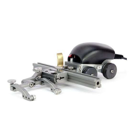
- Page 1 MICROBE BT0179 Rev 04.5 Manual Magnetic Scanner...
- Page 2 SAFETY WARNINGS / PRECAUTIONS KEEP THIS MANUAL – DO NOT LOSE THIS MANUAL IS PART OF THE MICROBE AND MUST BE RETAINED FOR THE LIFE OF THE PRODUCT. PASS ON TO SUBSEQUENT OWNERS. Ensure any amendments are incorporated with this document.
-
Page 3: Table Of Contents
TABLE OF CONTENTS Identification Chapter 1.1. Product brand 1.2. Manufacturer Product Specifications Chapter 2.1. Intended Use 2.1.1. Operating limits 2.1.2. Operating environment 2.2. Dimensions and Weight 2.4. Environmental Sealing 2.5. Performance Specifications Definitions Chapter 3.1. Definition of Symbols System components Chapter 4.1. Component Identification 4.2. - Page 4 Preparation for Use Chapter 5.1. Configurations 5.1.1. One Probe Cantilever 5.1.2. Two Probe 5.1.3. Two Probe Cantilever 5.1.4. Four Probe Operation Chapter 6.1. MICROBE Setup on a Scanning Surface Maintenance Chapter Troubleshooting Chapter 8.1. Technical Support Spare Parts Chapter 9.1. MICROBE Cart 9.2. Kit Components 9.2.1. Encoder Connector Type...
- Page 5 9.6. Variable Components 9.6.1. Frame Bars Disposal Chapter Limited Warranty Chapter PAGE iv of iv...
-
Page 6: Product Brand
Chapter 1 IDENTIFICATION 1.1. Product brand This user manual describes the proper safety precautions, setup and use of the MICROBE manual magnetic scanner. 1.2. Manufacturer DISTRIBUTOR: MANUFACTURER: Jireh Industries Ltd. 53158 Range Road 224 Ardrossan, Alberta, Canada T8E 2K4 Phone: 780.922.4534 jireh.com... -
Page 7: Product Specifications
Chapter 2 PRODUCT SPECIFICATIONS 2.1. Intended Use The MICROBE is a hand held scanner with built-in encoder and magnetic wheels. It is designed to translate phased array and/or TOFD probes around ferrous piping and vessels. 2.1.1. Operating limits Minimum Maximum Pipe/tube range, outer diameter 3.8 cm... -
Page 8: Environmental Sealing
- Double wheel dimensions Fig. 2 8 cm 3.15 in (Fig. 1-A) 17.2 cm 6.8 in (Fig. 1-B) 8.1 cm 3.2 in (Fig. 1-C) 11 cm 4.3 in (Fig. 2-D) Umbilical length (standard kit): (16.4 in) Cart weight: 0.77 kg (1.7 lb)* *Cart weight with umbilical housing but not including cabling. -
Page 9: Definitions
Chapter 3 DEFINITIONS 3.1. Definition of Symbols Instructions to ‘look here’ or to ‘see this part’ Denotes movement. Instructing user to carry out action in a specified direction. Indicates alignment axis, can also indicate insertion or movement of parts. PAGE 4 of 42... -
Page 10: System Components
Chapter 4 SYSTEM COMPONENTS 4.1. Component Identification - MICROBE Cart - MICROBE/ROTIX Umbilical Housing - Frame Bar Fig. 3 Fig. 4 Fig. 5 BTA010 UMA012- BG0038- - Magnetic Wheel - Slip Joint Probe Holder - Irrigation Kit Fig. 6 Fig. 7 Fig. -
Page 11: Tools
Fig. 14 Fig. 15 The 3 mm hex driver is sufficient for all typical operations and (Fig. 14) adjustments of the MICROBE. The 3/8 in wrench is used to remove and install buttons on the probe (Fig. 15) holders. 4.2.2. Optional tools Some specialized adjustments require tools that are not included with this kit. -
Page 12: Cart
4.3. Cart - Cart Fig. 20 4.3.1. Cart Body A housing for the main encoder and provides a mounting base for probe holders and the umbilical housing (Fig. 20) 4.3.2. Cart Handle The handle is used to both manage cabling and provide an ergonomic grip during use. -
Page 13: Wheels
4.3.4. Wheels The wheels of the cart are interchangeable. To remove/install the cart wheels, insert the provided 3 mm hex driver in the end of the (Fig. 14) shaft opposite the wheel you wish to remove. Thread or unthread the - Umbilical housing removal Fig. -
Page 14: Front Pivot
TIP: If the umbilical does not slide freely from the body, you may need to push on the wing knob to loosen the dovetail nut. 4.3.6. Front Pivot The front pivot offers an attachment point for various frame bars. - Pivot - Frame bar attachment Fig. -
Page 15: Pivot Buttons
- Screw to scanner body - Return pivot position Fig. 30 Fig. 31 Using the supplied 3 mm hex driver, screw the rear pivot to the cart (Fig. 30). Rotate the pivot to the original position and lock the side mounted lever (Fig. -
Page 16: Slip Joint Probe Holder
4.6. Slip Joint Probe Holder Frame Bar Probe Holder Adjustment Knob Latch Swing Arm Knob Yoke Probe Holder Arm Adjustment Knob Probe Holder Arm Arm Clamp Screw Pivot Buttons - Slip joint probe holder Fig. 34 4.6.1. Probe Holder Setup To mount a UT wedge in the probe holder, follow these steps: - Attach to frame bar - Adjust on frame bar... - Page 17 Use swing arm knob to position the swing arm (Fig. 37). TIP: The swing arm is typically used to adjust TOFD center to center distance relative to the phased array probes on a four probe configuration (Fig. 33). Using the supplied 3/8 in wrench , place the pivot buttons as required (Fig.
-
Page 18: Probe Holder Adjustment
4.6.2. Probe Holder Adjustment To adjust the probe holder, follow these steps: 6 mm approx. - Lift to latched position - Lower to scanning surface Fig. 42 Fig. 43 Ensure probe holder is in latched, upper position . If the probe holder (Fig. - Page 19 To adjust the probe holder’s force, follow these steps: NOTE: Do not perform this operation on scanning surface. - Lift slightly and press Latch - Unlatched position Fig. 46 Fig. 47 Ensure the probe holder is in the upright latched position (Fig.
-
Page 20: Slip Joint Probe Holder Left/Right Conversion
4.6.4. Slip Joint Probe Holder Left/Right Conversion To reverse the probe holder, follow these steps: - Unscrew yoke pivot screw - Remove arms Fig. 51 Fig. 52 Unscrew the yoke from the swing arm (Fig. 51) Loosen the probe holder arm adjustment knob and arm clamp screw. Slide the arms from the yoke (Fig. - Page 21 - Position swing arm - Install yoke to swing arm Fig. 55 Fig. 56 Loosen the swing arm knob and slide the swing arm to the opposite end of the probe holder bracket or preferred position. Tighten swing arm (Fig. 55) knob.
-
Page 22: Vertical Probe Holder
4.7. Vertical Probe Holder Latch Probe Holder Adjustment Knob Vertical Adjustment Knob Pivot Buttons Probe Holder Arms Yoke Probe Holder Arm Adjustment Knob Transverse Adjustment Screw Frame Bar - Vertical probe holder Fig. 58 4.7.1. Probe Holder Setup - Adjust on frame bar - Vertical adjustment - Place buttons Fig. - Page 23 To mount a UT wedge in the probe holder, follow these steps: - Adjust inner arm - Adjust outer arm - Tighten arm knob Fig. 62 Fig. 63 Fig. 64 Position the wedge on the inner probe holder arm (Fig. 62) TIP: The probe holder yoke can accommodate many different probe and wedge sizes of varying widths.
-
Page 24: Probe Holder Vertical Adjustment
4.7.2. Probe Holder Vertical Adjustment To adjust the probe holder vertically, follow these steps: approx. - Latch probe holder - Lower toward scan surface Fig. 65 Fig. 66 Ensure the probe holder is in the latched, upper position. Do this by lifting the probe holder till the latch is fully exposed and snaps out to lock (Fig. -
Page 25: Probe Holder Transverse Adjustment
4.7.3. Probe Holder Transverse Adjustment To adjust the probe holder’s transverse angle, follow these steps: - Loosen 3 mm screw - Rotate and tighten - Stop post locates 90° Fig. 69 Fig. 70 Fig. 71 Ensure the probe holder is in latched, upper position (Fig. -
Page 26: Probe Holder Longitudinal Adjustment
4.7.4. Probe Holder Longitudinal Adjustment To adjust the probe holder’s vertical angle for longitudinal scanning, follow these steps: - Loosen 3 mm screw - Rotate to position - Line up markers Fig. 72 Fig. 73 Fig. 74 Ensure the probe holder is in latched, upper position (Fig. -
Page 27: Probe Holder Left/Right Conversion
4.7.5. Probe Holder Left/Right Conversion To reverse the probe holder, follow these steps: NOTE: To perform this operation the 1.5 mm hex wrench (Fig. 16) is required. - Unscrew yoke pivot screw Fig. 75 - Remove probe holder arms Fig. 76 Ensure the probe holder is in latched, upper position (Fig. - Page 28 - Screw yoke to opposite side - Lower 90° stop post Fig. 79 Fig. 80 Mount the yoke to the opposite side of the base using the supplied 3 mm hex driver (Fig. 79) TIP: Keep the yoke level with the base as to ensure no conflicts with the plunger/ set screw attached to the yoke.
-
Page 29: Magnetic Wheel Kit
4.8. Magnetic Wheel Kit WARNING! MAGNETIC MATERIAL. The magnetic wheel kit produce a magnetic field which may cause failure or permanent damage to items such as watches, memory devices, CRT monitors, medical devices or other electronics. People with pacemakers or ICD’s must stay at least 25 cm away. -
Page 30: Pre-Amp Bracket
On the magnetic wheel to be attached, locate the threaded side of the magnetic wheel, orient the threaded side towards the cart (Fig. 83) Overcome the magnetic resistance to screw the additional wheel to the axle of the wheel block (Fig. -
Page 31: Preparation For Use
Chapter 5 PREPARATION FOR USE 5.1. Configurations 5.1.1. One Probe Cantilever - One probe cantilever configuration Fig. 87 5.1.2. Two Probe - Two probe configuration Fig. 88 PAGE 26 of 42... -
Page 32: Two Probe Cantilever
5.1.3. Two Probe Cantilever - Two probe cantilever configuration Fig. 89 5.1.4. Four Probe - Four probe configuration Fig. 90 BT0179 Rev 04.5 PAGE 27 of 42... -
Page 33: Operation
Chapter 6 OPERATION 6.1. MICROBE Setup on a Scanning Surface - Assemble configuration Fig. 91 Assemble the appropriate configuration to the cart (Fig. 91) Install the wedge and probes that will be used (see Slip Joint Probe Holder on page 11) - Page 34 - Lower pivot nose Fig. 94 Adjust the pivot nose angle to align the frame bar parallel with the tangent (Fig. 94) of the scan surface (Fig. 95) - Parallel with scan surface tangent - Parallel with scan surface tangent Fig.
-
Page 35: Maintenance
Chapter 7 MAINTENANCE General cleaning of components is important to keep your system working well. All components that have no wiring or cables are completely waterproof. Components can be washed with warm water, dish soap and a medium bristle brush. Before using the scanner, ensure all connectors are free of water and moisture. -
Page 36: Troubleshooting
Ensure the brake is unlocked when using the become loose. scanner (see Brake Handle on page 7) 8.1. Technical Support For technical support, contact Jireh Industries (see Jireh Industries Ltd. on page 1). BT0179 Rev 04.5 PAGE 31 of 42... -
Page 37: Spare Parts
Chapter 9 SPARE PARTS To order accessories or replacement parts for your MICROBE system. (contact Jireh Industries Ltd. on page 1) NOTE: These drawings are for parts order. This is not a list of kit contents. 9.1. MICROBE Cart - MICROBE cart parts Fig. - Page 38 BOM ID Part # Description BTS040 MICROBE/ROTIX Front Pivot BT0069 Mini Wing Knob, M5 x 0.8 x 6 mm, SST BTS031 Magnetic Wheel BTS045 Base Cart BTS046 Brake Handle BT0014 Dovetail Nut BT0150 Handle - MICROBE cart Fig. 98 BT0179 Rev 04.5...
-
Page 39: Kit Components
(see Frame Bars) UMA012-X-05 Umbilical Housing (see Encoder Connector) CMG007 Irrigation Kit PHG014 Probe Holder Spare Parts Kit, 2 Probe MD050-008 SHCS, M4x0.7 x 8 , SST BTS042 MICROBE/ROTIX Pivot Tail EA470 Wrench - Kit components Fig. 99 PAGE 34 of 42... -
Page 40: Encoder Connector Type
(17.72 (19.69 BG0038-45 BG0038-50 BG0038-55 (21.65 9.2.1. Encoder Connector Type Connector Connector Company/Instrument Company/Instrument Type Type Olympus - OmniScan MX / Zetec - ZIRCON, TOPAZ Sonotron - Isonic Olympus - Focus LT / Zetec Z-Scan / Eddyfi Ectane 2 GE - USM Vision Olympus - OmniScan MX2, OmniScan SX Sonatest - VEO, PRISMA TD - Focus Scan, Handy Scan, Pocket Scan... -
Page 41: Probe Holders
9.4. Probe Holders 9.4.1. Slip Joint Probe Holder Parts BOM ID Part # Description PH0104 Knurled Knob, M4 x 0.7 x 18 , 4 mm stand off, SST PH0082 Knurled Knob, M4 x 0.7 x 10 , 3 mm stand off, SST PHS022 Slip Joint Probe Holder Subassembly see Swing Arm Style... -
Page 42: Vertical Probe Holder Parts
9.4.2. Vertical Probe Holder Parts BOM ID Part # Description PHS028 Vertical Probe Holder Subassembly PH0082 Knurled Knob, M4 x 0.7 x 10 mm, 3 mm stand off, SST MD050-010 SHCS, M4 x 0.7 x 10 mm, SST see Yoke Style see Arm Style PH0011-X Pivot Button Style... -
Page 43: Probe Holder Components
Conical Head (0.20 Zetec PA/TOFD Internal 9.5. Probe Holder Components Part # Length Part # Length 9.5.1. Arm Style (1.97 (3.94 BG0038-05 BG0038-10 Arm Style Part # Arm Style Part # BG0038-15 (5.91 BG0038-20 (7.87 Part # Arm Style Arm Style Part # Standard, Flat PH0090... - Page 44 (0.12 (0.09 9.6. Variable Components (0.20 Conical Head Zetec PA/TOFD Internal 9.6.1. Frame Bars Part # Length Part # Length (1.97 (3.94 BG0038-05 BG0038-10 BG0038-15 (5.91 BG0038-20 (7.87 (9.84 (11.81 BG0038-25 BG0038-30 BG0038-35 (13.78 BG0038-40 (15.75 (17.72 (19.69 BG0038-45 BG0038-50 BG0038-55 (21.65 - Frame bar selection...
- Page 45 Electronic Equipment (WEEE), this symbol indicated that the product must not be disposed of as unsorted municipal waste, but should be collected separately. Refer to Jireh Industries for return and/or collection systems available in your country. PAGE 40 of 42...
- Page 46 THREE (3) YEARS from the original date of purchase. If a defect exists, at its option Jireh will (1) repair the product at no charge, using new or refurbished replacement parts, (2) exchange the product with a product that is new...
- Page 47 Changes or modifications to this unit or accessories, not expressly approved by the party responsible for compliance could void the user’s authority to operate the equipment. All specifications are subject to change without notice. © 2018 Jireh Industries Ltd. PAGE 42 of 42...
- Page 48 Jireh Industries Ltd. 53158 Range Road 224 Ardrossan, Alberta Canada T8E 2k4 780-922-4534 jireh.com...
Need help?
Do you have a question about the MICROBE and is the answer not in the manual?
Questions and answers