Table of Contents
Advertisement
Quick Links
Advertisement
Table of Contents

Related Manuals for Jireh ROTIX CE0142


Summary of Contents for Jireh ROTIX CE0142
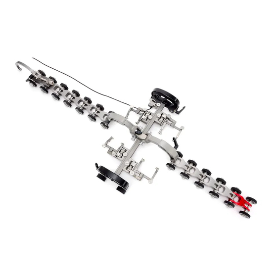
- Page 1 ROTIX CE0142 Rev 03 Reduced Width Chain Scanner...
- Page 2 SAFETY WARNINGS / PRECAUTIONS KEEP THIS MANUAL – DO NOT LOSE THIS MANUAL IS PART OF THE ROTIX AND MUST BE RETAINED FOR THE LIFE OF THE PRODUCT. PASS ON TO SUBSEQUENT OWNERS. Ensure any amendments are incorporated with this document. DANGER! The ROTIX is designed for a specific use.
-
Page 3: Table Of Contents
TABLE OF CONTENTS Identification Chapter 1.1. Product Information 1.2. Manufacturer Product Specifications Chapter 2.1. Intended use 2.1.1. Operating Limits 2.1.2. Operating environment 2.2. Dimensions and Weight 2.3. Environmental Sealing 2.4. Performance Specifications Definitions Chapter 3.1. Definition of symbols System Components Chapter 4.1. Component Identification 4.2. - Page 4 4.8.2. Probe Holder Vertical Adjustment 4.8.3. Probe Holder Transverse Adjustment 4.8.4. Probe Holder Longitudinal Adjustment 4.8.5. Probe Holder Left/Right Conversion 4.9. Magnetic Wheel Kit Configurations Chapter 5.1. Single Probe Scanning 5.2. Two Probe Scanning Operation Chapter 6.1. Setup of ROTIX on a Scanning Surface Maintenance Chapter Service and Support...
- Page 5 Limited Warranty Chapter Appendix Chapter 12.1. Reduced Width Chain Configuration Setup Chart PAGE iv of iv...
-
Page 6: Identification
The manually operated ROTIX reduced width chain scanner provides encoded probe positions of one or two probes while requiring a minimal footprint. 1.2. Manufacturer DISTRIBUTOR: MANUFACTURER: Jireh Industries Ltd. 53158 Range Road 224 Ardrossan, Alberta, Canada T8E 2K4 780.922.4534 jireh.com... -
Page 7: Product Specifications
Chapter 2 PRODUCT SPECIFICATIONS 2.1. Intended use The scanner’s primary purpose is to move an inspection tool over a cylindrical surface for inspection of pipes and vessels. 2.1.1. Operating Limits Minimum Maximum Pipe/Tube Range 10.2 cm 96.5 cm (4 in) (38 in) Radial Scanner Clearance: 9 cm... - Page 8 - Two probe dimensions Fig. 2 10 cm 3.9 in 21.8 cm 8.6 in 12 cm 4.7 in 25 cm 9.8 in Link Weight:* 0.64 kg 1.4 lb Encoder Cable Length:** 16.4 ft * Link weight does not include cabling, frame bar or probe holder(s). ** Custom encoder lengths available.
-
Page 9: Environmental Sealing
2.3. Environmental Sealing Watertight (submersible) (contact Jireh Industries Ltd. on page 1 for additional details) 2.4. Performance Specifications X-Axis encoder Resolution 16.3 counts/mm (414.5 counts/inch) PAGE 4 of 38... -
Page 10: Definitions
Chapter 3 DEFINITIONS 3.1. Definition of symbols Instructions to ‘look here’ or to ‘see this part’. Denotes movement. Instructing user to carry out action in a specified direction. Indicates alignment axis. Alerts user that view has changed to a reverse angle. CE0142 Rev 03 PAGE 5 of 38... -
Page 11: System Components
Chapter 4 SYSTEM COMPONENTS 4.1. Component Identification - Reduced width ROTIX link - Frame bar - Vertical probe holder Fig. 3 Fig. 4 Fig. 5 CES046- BG0038- PHA015- - Short link - Short link with dovetail - Long link Fig. 6 Fig. - Page 12 - 3 mm hex driver - 3/8 in wrench - ROTIX reduced width case Fig. 12 Fig. 13 Fig. 14 EA414 EA470 CEA013 CE0142 Rev 03 PAGE 7 of 38...
-
Page 13: Tools
4.2. Tools 4.2.1. Included tools - 3 mm hex driver - 3/8 in wrench Fig. 15 Fig. 16 The 3 mm hex driver is sufficient for all typical operations and (Fig. 15) adjustments of the ROTIX. The 3/8 in wrench is used to remove and (Fig. -
Page 14: Reduced Width Link
4.3. Reduced Width Link The reduced width link offers a means of non- ferrous scanning requiring a minimal footprint. The encoder is built-in to the reduced width link. 4.3.1. Attach a Frame Bar To attach a frame bar to the reduced width link, follow these steps: Loosen the black wing knobs - Reduced width link... -
Page 15: Wheel Removal/Installation
Position the frame bar where required and tighten the black wing knobs. - Tighten wing knobs Fig. 20 4.3.2. Wheel Removal/Installation By hand, tightly grip the wheel to be removed. Using the supplied 3 mm hex driver , loosen the (Fig. -
Page 16: Chain Connection
4.6. Chain Connection - Pull out and twist pins - Align mounting holes - Release pins Fig. 24 Fig. 25 Fig. 26 To connect chain components, see these following steps: Pull the pins out from the wheels, twist a quarter turn latching the pins in a retracted state (Fig. -
Page 17: Cable Management System
Cable Management System 4.7.1. - Cable management Fig. 30 TIP: When using the cable management, ensure the dovetail link is placed 2 in the chain behind the overhead adjustable link. 4.7.2. Cable Management Dovetail Mount To attach the cable management, follow these steps: - Loosen and slide on - Tighten knob Fig. -
Page 18: Cable Management Setup
Loosen the knob on the cable management dovetail mount. Slide the mount onto the dovetail link (Fig. 31) Once centred on the dovetail link, tighten the cable management’s dovetail mount knob (Fig. 32) 4.7.3. Cable Management Setup The cable management is offered in a variety of lengths and provides a means of bundling and protecting cables and hoses that run to the scanner. -
Page 19: Clamp Setup
4.7.4. Clamp Setup If the sleeving becomes disconnected from the cable management dovetail mount, follow these instructions to re-attach the sleeving and dovetail mount. Loosen the clamp screw using the supplied 3 mm hex driver. - Slide tube around mount Fig. -
Page 20: Vertical Probe Holder
4.8. Vertical Probe Holder Latch Probe Holder Adjustment Knob Vertical Adjustment Knob Pivot Buttons Probe Holder Arms Yoke Probe Holder Arm Adjustment Knob Transverse Adjustment Screw Frame Bar - Vertical probe holder Fig. 40 4.8.1. Probe Holder Setup To mount a UT wedge in the probe holder, follow these steps: - Adjust on frame bar - Vertical adjustment - Place buttons... -
Page 21: Probe Holder Vertical Adjustment
- Adjust inner arm - Adjust outer arm - Tighten arm knob Fig. 44 Fig. 45 Fig. 46 Position the wedge on the inner probe holder arm. TIP: The probe holder yoke can accommodate many different probe and wedge sizes of varying widths. It is best to centre the wedge with the yoke’s pivot axis. -
Page 22: Probe Holder Transverse Adjustment
Ensure the probe holder is in the latched, upper position. Lift the probe holder until the latch is fully exposed and snaps out to lock (Fig. 47) Loosen the vertical adjustment knob and slide the probe holder down until the wedge is approximately 6 mm (¼ in) above inspection surface (Fig. -
Page 23: Probe Holder Longitudinal Adjustment
Ensure the probe holder is in latched, upper position (Fig. 47) Using the supplied 3 mm hex driver loosen the transverse adjustment screw and rotate the yoke about the vertical shaft achieving the desired (Fig. 51) angle. Tighten the transverse adjustment screw (Fig. -
Page 24: Probe Holder Left/Right Conversion
4.8.5. Probe Holder Left/Right Conversion To reverse the probe holder, follow these steps: NOTE: To perform this operation the 1.5 mm hex wrench (Fig. 17) is required. - Unscrew yoke pivot screw - Remove probe holder arms Fig. 57 Fig. 58 Ensure the probe holder is in latched, upper position (Fig. - Page 25 - Screw yoke to opposite side - Lower 90° stop post Fig. 61 Fig. 62 Mount the yoke to the opposite side of the base using the supplied 3 mm hex driver (Fig. 61) TIP: Keep the yoke level with the base as to ensure no conflicts with the plunger/set screw attached to the yoke.
-
Page 26: Magnetic Wheel Kit
4.9. Magnetic Wheel Kit WARNING! MAGNETIC MATERIAL. The magnetic wheel kit produce a magnetic field which may cause failure or permanent damage to items such as watches, memory devices, CRT monitors, medical devices or other electronics. People with pacemakers or ICD’s must stay at least 25 cm (10 in) away. When the use of a chain scanner is not appropriate, the magnetic wheel kit (Fig. -
Page 27: Configurations
Chapter 5 CONFIGURATIONS 5.1. Single Probe Scanning - Single probe scanning Fig. 66 5.2. Two Probe Scanning - Two probe scanning Fig. 67 PAGE 22 of 38... -
Page 28: Operation
Chapter 6 OPERATION 6.1. Setup of ROTIX on a Scanning Surface Determine the diameter of the pipe or tube to be scanned. Included in the ROTIX kit and in this manual, is a setup chart which indicates the number of links required based on the diameter of the pipe or tubing (Fig. - Page 29 - Assemble configuration Fig. 71 On a flat surface, connect the appropriate number of links (see Chain Connection on page 11) indicated on the ROTIX setup chart. Arrange the link setup so the buckle and catch link will be 180° opposite of the scanner body (Fig.
- Page 30 - Hook buckle to catch link Fig. 73 - Adjust pressure of buckle Fig. 74 Bring the buckle arm towards the catch link. Hook the buckle’s arm to the middle axle of the catch link . The buckle adjustment knob may have to (Fig.
- Page 31 - Configured four probe configuration Fig. 76 Route all cabling and hoses to the the cable (Only encoder cable shown) management (see Cable Management System on page 12) Lower probe holders to the scan surface (see Vertical Probe Holder on page 15) PAGE 26 of 38...
-
Page 32: Maintenance
Chapter 7 MAINTENANCE General cleaning of components is important to keep your system working well. All components that have no wiring or cables are completely waterproof. Components can be washed with warm water, dish soap and a medium bristle brush. After washing your system, use a light oil to lubricate the slide and the adjustment screw on the buckle component . - Page 33 PAGE 28 of 38...
-
Page 34: Service And Support
Reconfigure the probe holder(s) as per setup properly. instructions (see Probe Holder Vertical Adjustment on page 16). 8.2. Technical Support For technical support contact Jireh Industries (see “Jireh Industries Ltd.” on page 1) CE0142 Rev 03 PAGE 29 of 38... -
Page 35: Spare Parts
Chapter 9 SPARE PARTS To order accessories or replacement parts for your ROTIX system. (contact Jireh Industries Ltd. on page 1) NOTE: These drawings are for parts order. This is not a list of kit contents. 9.1. Kit Components BOM ID Part #... -
Page 36: Encoder Connector Type
Swing Arm Style Part # Length Swing Arm Style Part # NOTE: Additional encoder connector styles available. Short PH0069 Long PH0100 (contact Jireh Industries Ltd. on page 1) (1.61 (1.81 9.2. Accessories Part # Length Part # Length BG0090-05 BG0090-10 (1.97... -
Page 37: Pre-Amp Bracket
9.2.2. Pre-Amp Bracket Part # Description CES029 Pre-Amp Bracket CES029-V Pre-Amp Bracket with Velcro - Pre-amp bracket Fig. 81 9.2.3. Magnetic Wheel Kit Part # Description BTG014 Magnetic Wheel Kit - Magnetic wheel kit Fig. 82 PAGE 32 of 38... -
Page 38: Vertical Probe Holder Parts
9.3. Vertical Probe Holder Parts BOM ID Part # Description PHS028 Vertical Probe Holder Subassembly PH0082 Knurled Knob, M4 x 0.7 x 10 mm, 3 mm stand off, SST see Arm Style PH0011-X Pivot Button Style (see Pivot Button Style) see Yoke Style MD050-010 SHCS, M4 x 0.7 x 10 mm, SST - Vertical probe holder... -
Page 39: Probe Holder Components
NOTE: Additional probe holder pivot button types available. Conical Head (0.20 Zetec PA/TOFD Internal Zetec PA/TOFD Conical Head (0.12 (0.20 (0.09 Internal (contact Jireh Industries Ltd. on page 1) Part # Length Part # Length BG0038-05 (1.97 BG0038-10 (3.94 Conical Head (0.20... -
Page 40: Disposal
, this symbol indicated that the product (WEEE) must not be disposed of as unsorted municipal waste, but should be collected separately. Refer to Jireh Industries for return and/or collection systems available in your country. CE0142 Rev 03 PAGE 35 of 38... - Page 41 THREE (3) YEARS from the original date of purchase. If a defect exists, at its option Jireh will (1) repair the product at no charge, using new or refurbished replacement parts, (2) exchange the product with a product that is new...
- Page 42 Changes or modifications to this unit or accessories, not expressly approved by the party responsible for compliance could void the user’s authority to operate the equipment. All specifications are subject to change without notice. © 2016 Jireh Industries Ltd. CE0142 Rev 03 PAGE 37 of 38...
- Page 43 Chapter 12 APPENDIX 12.1. Reduced Width Chain Configuration Setup Chart PIPE OD RANGE LINKS LONG SHORT (in) (in) (mm) (mm) 10.4 10.6 11.4 11.4 12.2 11.4 12.2 13.0 12.2 13.3 14.1 13.3 14.1 14.7 14.9 15.7 15.8 16.6 15.8 16.5 17.1 17.3 18.1...
- Page 44 Jireh Industries Ltd. 53158 Range Road 224 Ardrossan, Alberta Canada T8E 2k4 780-922-4534 jireh.com...
Need help?
Do you have a question about the ROTIX CE0142 and is the answer not in the manual?
Questions and answers