Table of Contents

Related Manuals for Jireh Rotix


Summary of Contents for Jireh Rotix
- Page 1 CE0131 Rev 01.5 Chain Corrosion Scanner...
- Page 2 SAFETY WARNINGS \ PRECAUTIONS KEEP THIS MANUAL – DO NOT LOSE THIS MANUAL IS PART OF THE ROTIX AND MUST BE RETAINED FOR THE LIFE OF THE PRODUCT. PASS ON TO SUBSEQUENT OWNERS. Ensure any amendments are incorporated with this document.
-
Page 3: Table Of Contents
Chapter 2.1. Centre Chain Configuration 2.2. Cantilever Chain Configuration Operation Chapter 3.1. Setup of a Chain Rotix on a Scanning Surface System Components Chapter 4.1. Corrosion Link 4.1.1. Mounting a Frame Bar 4.1.2. Index Encoder Connection 4.1.3. Encoder Connection 4.1.4. Brake 4.1.5. - Page 4 4.4. Frame Bar with Ruler 4.5. Pivot Buttons 4.6. Chain Components 4.6.1. Chain Connection 4.6.2. Ratchet Lever 4.7. Index Encoder 4.8. Cable Clips 4.9. Cable Management System 4.9.1. Zipper Tube Dovetail Mount 4.9.2. Zipper Tube Setup 4.9.3. Clamp Setup Service and Support Chapter 5.1.
- Page 5 PAGE iv of iv...
-
Page 6: Introduction
16.3 counts/mm (414.5 counts/inch) Index encoder resolution 40.3 counts/mm (1023.9 counts/inch) 1.1.3. Operating environment The ROTIX chain scanner is designed for use in an industrial environment that is between -20° C and 50° C (-4° F) (122° F) 1.1.4. Environmental Sealing Dust tight, water tight (not submersible). -
Page 7: Hardware
The 3 mm hex driver (Fig. 2) - 3/8 in wrench sufficient for all typical operations Fig. 3 and adjustments of the ROTIX. The 3/8 in wrench is used to remove and install pivot buttons on the (Fig. 3) probe holders. -
Page 8: Chain Configuration Setup Chart
1.4. Chain Configuration Setup Chart P I P E S I Z E L I N K S SHORT* LONG (in) (in) (mm) (mm) *Short includes: Short Link, Dovetail Link, Red Catch Link 10.4 10.6 11.4 11.4 12.2 11.4 Max of 12.2 13.0 12.2... -
Page 9: Configuration
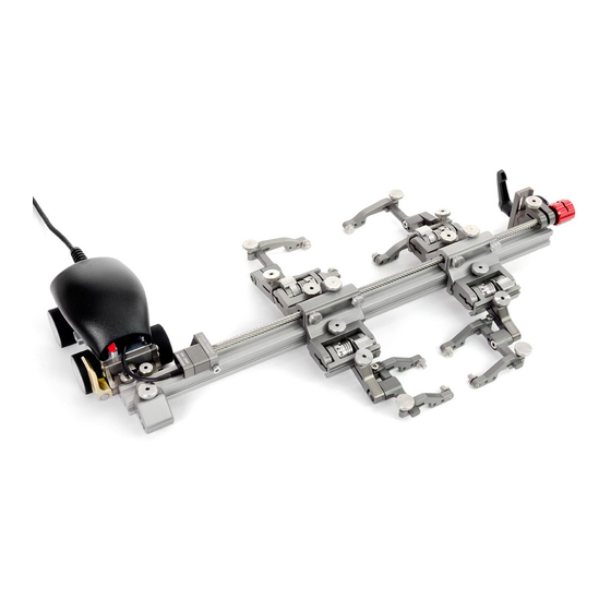
Chapter 2 CONFIGURATION 2.1. Centre Chain Configuration - Centre chain configuration Fig. 4 PAGE 4 of 32... -
Page 10: Cantilever Chain Configuration
2.2. Cantilever Chain Configuration - Cantilever chain configuration Fig. 5 PAGE 5 of 32 CE0131 Rev 01.5... -
Page 11: Operation
Chapter 3 OPERATION 3.1. Setup of a Chain Rotix on a Scanning Surface Determine the diameter of the pipe or tube to be scanned. Included in the ROTIX kit and in this manual is a setup chart (see Chain Configuration Setup Chart on . - Page 12 On a flat surface, connect the appropriate number of links (see Chain Connection on page 19) indicated on the ROTIX setup chart. Arrange the link setup with the buckle and catch link 180° opposite of the corrosion link (Fig. 8) TIP: Place the dovetail link 2 the chain (Fig.
- Page 13 - Press down to lock Fig. 12 Rotate the buckle adjustment knob until the buckle’s lever can be pushed down . The tightness of the ROTIX on the pipe can locking the buckle in place (Fig. 12) be adjusted using the buckle adjustment knob (Fig.
- Page 14 - Cable and irrigation setup Fig. 13 Route all cabling and hoses (Encoder cable and sample irrigation tube shown) the zipper tube (see Cable Management System on page 21) Lower probe holders to the scan surface (see Probe Holder Setup on page 14) Release the brake to commence scanning (see Brake on page 11) PAGE 9 of 32...
-
Page 15: System Components
Chapter 4 SYSTEM COMPONENTS 4.1. Corrosion Link The corrosion link provides braking for the system as well as an internal encoder connected to the wheels. A connection plug exists for index encoding. A mounting point for a frame bar is also provided. - Corrosion link Fig. -
Page 16: Index Encoder Connection
4.1.2. Index Encoder Connection The index encoder connection is located along the side of the (Fig. 17) corrosion link. The cable from the index encoder (see Index Encoder on page 20) connects to this point. - Index encoder connection Fig. 17 4.1.3. -
Page 17: Tail
4.1.6. Tail The tail is a mounting point for (Fig. 21) the buckle and chain links. Use the supplied 3 mm hex driver to install or remove the tail. - Tail 4.2. Carrier Fig. 21 With the use of a leadscrew, the carrier can move along the length of the frame bar. - Carrier handle latch Fig. -
Page 18: Index Nuts
4.2.2. Index Nuts - Index nuts Fig. 25 The index nuts located along (Fig. 25) the frame bar offer index positions during scans. The arrow on each nut confirms alignment with the ruler on the frame bar. NOTE: The index nuts can be repositioned, placement of the index nuts works in conjunction with common probe... -
Page 19: Heavy Duty Vertical Probe Holder
4.3. Heavy Duty Vertical Probe Holder Latch Probe Holder Arm Adjustment Knob Yoke Probe Holder Arms Pivot Buttons Arm Clamp Screw Probe Holder Adjustment Knob Vertical Adjustment Knob - Heavy duty vertical probe holder 4.3.1. Probe Holder Setup Fig. 27 - Mount probe holder to carrier - Vertical adjustment Fig. -
Page 20: Probe Holder Vertical Adjustment
Loosen the probe holder adjustment knob and remove the outer probe holder arm (Fig. 30) Loosen the arm clamp screw (Fig. 31). Place the wedge on the pivot button of the inner probe holder (Fig. 31). - Remove outer arm - Pivot buttons Fig. -
Page 21: Probe Holder Left/Right Conversion
4.3.3. Probe Holder Left/Right Conversion - Remove yoke - Orient to opposite side Fig. 36 Fig. 37 Using the supplied 3 mm driver, unscrew the yoke (Fig. 36). Position the yoke and arms to the opposite side of the probe holder (Fig. -
Page 22: Probe Holder 90° Adjustment
Position the pivot buttons to the inside of the probe holder arms (Fig. 40) Place the probe holder arms on the yoke and tighten the arm clamp screw and probe holder adjustment knob (Fig. 41) Screw the yoke to the probe holder (Fig. -
Page 23: Pivot Buttons
4.5. Pivot Buttons Available in a variety of shapes and sizes fitting various wedge dimensions. Use the supplied 3/8 in wrench (Fig. 3) remove and install pivot buttons (Fig. 45) - Pivot buttons Fig. 45 4.6. Chain Components The chain components are used to fasten a scanning cart circumferentially around a pipe or tubing. -
Page 24: Chain Connection
Fig. 54 Fig. 55 Fig. 56 The rachet lever is used with the buckle of the ROTIX system. Occasionally, movement of the lever locking position is required. The lever placement can be adjusted by following these steps: Pull the ratchet lever away from the base of which it is connected (Fig. -
Page 25: Index Encoder
4.7. Index Encoder The index encoder is used to provide positional feedback perpendicular to the scan direction of travel. - Loosen and slide post in place - Align and mount post Fig. 57 Fig. 58 To install the index encoder, loosen the clamp screw on the encoder with the supplied 3 mm hex driver (Fig. -
Page 26: Cable Clips
4.8. Cable Clips Clips have been provided to assist with cable management. Simply pinch the clip an and press it into the dovetail groove of the frame bar. - Pinch clip - Route cables Fig. 61 Fig. 62 4.9. Cable Management System - Cable management Fig. -
Page 27: Zipper Tube Dovetail Mount
4.9.1. Zipper Tube Dovetail Mount To attach a zipper tube for cable management, follow these steps: - Loosen and slide on - Tighten knob Fig. 64 Fig. 65 Loosen the knob on the zipper tube dovetail mount. Slide the mount onto the dovetail link (Fig. -
Page 28: Clamp Setup
Follow the cable placement zipping the tube closed and closing the zipper tube’s cable clip (Fig. 67) - Zip opposite end - Flexibility Fig. 68 Fig. 69 Once the cable is placed the entire length of tube, bring the zipper from the tubes opposite end, meeting at any point in the middle (Fig. -
Page 29: Service And Support
Scanner not set Reconfigure the scanner as per instructions probe contact. properly. (see Setup of a Chain Rotix on a Scanning Surface on page 6) 5.2. Technical Support For technical support contact Jireh Industries (see “Jireh Industries Ltd.” on page i) 5.3. -
Page 30: Spare Parts
Chapter 6 SPARE PARTS To order accessories or replacement parts for your ROTIX system. (contact Jireh Industries Ltd. on page i) NOTE: These drawings are for parts order. This is not a list of kit contents. 6.1. Corrosion Scanner BOM ID Part # Description DKS009-S-0.4 Index Encoder... -
Page 31: Kit Components
CES002 Short Link CES003 Catch Link (Red) CES005 Buckle CES009 Long Link CES024 Short Link with Dovetail CES067 Zipper Tube Mount CES066 Zipper Tube Clamp See Zipper Tube Length - Rotix corrosion kit parts Fig. 74 PAGE 26 of 32... -
Page 32: Encoder Connector Type
TD - Focus Scan, Handy Scan, Pocket Scan Pragma PAUT 16/128, PragmaLite / Pragma UT400 - Encoder connector type Fig. 75 NOTE: Additional encoder connector styles available. (contact Jireh Industries Ltd. on page i) 6.2.2. Zipper Tube Length Part # Length 4.5 m CX0141 (14.7 ft) -
Page 33: Hydroform™ Cart
6.3.2. HydroFORM™ Cart BOM ID Part # Description CA119 Urethane Molded Wheel Bearing - HydroFORM™ wheel replacement Fig. 78 PAGE 28 of 32... -
Page 34: Heavy Duty Vertical Probe Holder
6.4. Heavy Duty Vertical Probe Holder BOM ID Part # Description MD074-020 Arm Clamp Screw, BHCS, Metric SST PHS049 Heavy Duty Probe Holder Subassembly EA154 Probe Holder Arm Adjustment Knob See Heavy Duty Yoke Style PH0165 Probe Holder Arm PH0011-X See Pivot Button Style - Heavy duty vertical probe holder Fig. -
Page 35: Probe Holder Components
Length Part # Length (1.97 (3.94 BG0038-05 NOTE: Additional probe holder pivot button types available. BG0038-10 Part # Length Part # Length (contact Jireh Industries Ltd. on page i) (1.97 (3.94 BG0038-05 BG0038-10 BG0038-15 (5.91 BG0038-20 (7.87 BG0038-15 (5.91 BG0038-20 (7.87... -
Page 36: Limited Warranty
Jireh Industries. Before you deliver your product for warranty service you must phone Jireh and obtain an RMA number. This number will be used to process and track your product. Jireh is not responsible for any damage incurred during transit. - Page 37 Changes or modifications to this unit or accessories, not expressly approved by the party responsible for compliance could void the user’s authority to operate the equipment. All specifications are subject to change without notice. © 2015 Jireh Industries Ltd. PAGE 32 of 32...
- Page 38 Jireh Industries Ltd. 53158 Range Road 224 Ardrossan, Alberta Canada T8E 2k4 780-922-4534 jireh-industries.com...
Need help?
Do you have a question about the Rotix and is the answer not in the manual?
Questions and answers