Table of Contents
Advertisement
Quick Links
Advertisement
Table of Contents

Related Manuals for Jireh ROTIX


Summary of Contents for Jireh ROTIX
- Page 1 ROTIX CE0206 Rev 00 Manual Weld Frame Scanner...
- Page 2 SAFETY WARNINGS / PRECAUTIONS KEEP THIS MANUAL – DO NOT LOSE THIS MANUAL IS PART OF THE ROTIX AND MUST BE RETAINED FOR THE LIFE OF THE PRODUCT. PASS ON TO SUBSEQUENT OWNERS. Ensure any amendments are incorporated with this document.
- Page 3 PAGE ii of vi...
-
Page 4: Table Of Contents
TABLE OF CONTENTS Identification Chapter 1.1. Product Brand 1.1.1. Manufacturer Product Specifications Chapter 2.1. Base ROTIX Specifications 2.1.1. Intended Use 2.1.2. Operating Limits 2.1.3. Operating Environment 2.1.4. Dimensions and Weight 2.1.5. Environmental Sealing 2.1.6. Performance Specifications Definitions Chapter 3.1. Definition of Symbols 3.2. Definitions of Terms System Components Chapter 4.1. - Page 5 4.3. High Temperature Base System Components 4.3.1. HT Wheel Block with Handle 4.3.2. High Temperature Spring-Loaded Encoder 4.3.3. Slip Joint Probe Holder 4.3.4. High Temperature Standard Overtop Link 4.3.5. Frame Bar 4.3.6. Irrigation Kit 4.3.7. High Temperature Cable Management, Dovetail Mount 4.3.8. Cable Clip 4.3.9. HT QuickLink Components 4.3.9.1 Dovetail HT QuickLink 4.3.9.2 HT QuickLink Buckle 4.3.10. Tools 4.3.11. Case...
- Page 6 5.11. Magnetic Wheel Kit 5.12. Preamp Bracket 5.12.1. Mounting Preamp Bracket 5.12.2. Attaching Preamp with Screws 5.12.3. Attaching Preamp with Velcro Straps Operation Chapter 6.1. Setup of ROTIX on a Scanning Surface Maintenance Chapter Troubleshooting Chapter 8.1. Technical Support Service and Repair Chapter...
- Page 7 10.6.1. Arm Style 10.6.2. Yoke Style 10.6.3. Swing Arm Style 10.6.4. Pivot Button Style 10.7. Variable Components 10.7.1. Frame Bars 10.8. Case Disposal Chapter Limited Warranty Chapter Appendix Chapter 13.1. Weld Frame Setup Chart PAGE vi of vi...
-
Page 8: Identification
Chapter 1 IDENTIFICATION 1.1. Product Brand This user manual describes the proper safety precautions, setup and use of the ROTIX scanner. 1.1.1. Manufacturer Distributor: Manufacturer: Jireh Industries Ltd. 53158 Range Road 224 Ardrossan, Alberta, Canada T8E 2K4 780.922.4534 jireh.com CE0206 Rev 00... -
Page 9: Product Specifications
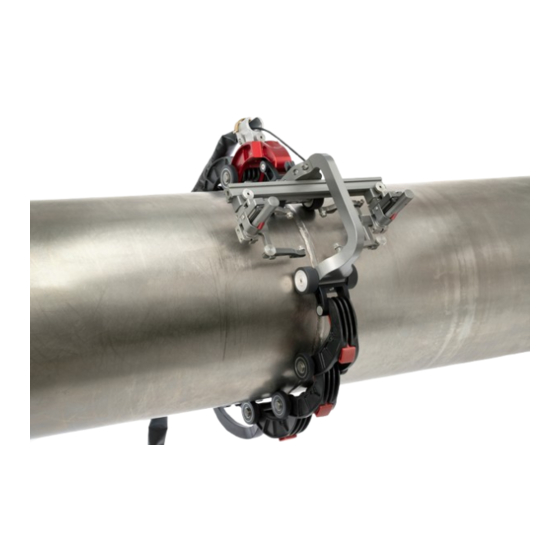
Chapter 2 PRODUCT SPECIFICATIONS 2.1. Base ROTIX Specifications 2.1.1. Intended Use ROTIX chain scanner is a manually operated scanner which provides encoded probe positions of two or four probes. The double wheel chain components straddle the weld and fasten a scanning frame circumferentially around pipe or tubing. -
Page 10: Dimensions And Weight
2.1.4. Dimensions and Weight - Frame dimensions Fig. 1 - High temperature frame dimensions Fig. 2 CE0206 Rev 00 PAGE 3 of 58... -
Page 11: Environmental Sealing
10.5 cm (4.1 in) (Fig. 2-6) Encoder cable length (16.4 in) 2.1.5. Environmental Sealing Watertight (submersible) (contact Jireh Industries Ltd. on page 1 for details). 2.1.6. Performance Specifications Category Specification X-Axis encoder resolution 9.05 counts/mm (230.0 counts/in) High Temperature X-Axis encoder 4.28 counts/mm... -
Page 12: Definitions
Chapter 3 DEFINITIONS 3.1. Definition of Symbols Instructions to ‘look here’ or to ‘see this part’. Denotes movement. Instructing user to carry out an action in a specified direction. Indicates alignment axis. Alerts user that the view has changed to a reverse angle. -
Page 13: System Components
Chapter 4 SYSTEM COMPONENTS 4.1. Base System Components 4.1.1. Wheel Block with Handle CES070 The wheel block provides stability and braking to the ROTIX system (Fig. 4) - Wheel block with handle Fig. 4 4.1.2. Spring-Loaded Encoder BGS053- The Spring-Loaded Encoder mounts to any standard frame bar. -
Page 14: Standard Overtop Link
4.1.4. Standard Overtop Link EJS013 The standard overtop link attaches to the double chain mount of the frame and reach overtop of the slip joint probe holders and connect to the QuickLinks (Fig. 7) - Standard overtop link Fig. 7 4.1.5. -
Page 15: Quicklink Components
4.1.7. QuickLink Components The QuickLink components fasten a ROTIX system circumferentially around a pipe or tube. 4.1.7.1 QuickLink ESS004 QuickLinks connect to assemble the required length to mount the system on a pipe (Fig. 10) - QuickLink Fig. 10 4.1.7.2 Dovetail QuickLink... -
Page 16: Tools
4.1.8. Tools Several tools are included for various scanner and accessory adjustments. (see Included Tools on page 16). 4.1.9. Case The system is provided with a rugged carrying case. CE0206 Rev 00 PAGE 9 of 58... -
Page 17: Compatible Components
4.2. Compatible Components 4.2.1. Cable Management, Dovetail Mount CES044- Cable management provides a means of protecting and organizing cables, tubes and hoses (Fig. 13) - Cable management, dovetail mount Fig. 13 4.2.2. Encoder Adapter UMA010- Adapt a scanner’s existing encoder connector to a different encoder style (Fig. -
Page 18: Frame Bar
4.2.4. Frame Bar BG0038- Frame bars are used to (Fig. 16) mount probe holders, probe positioning systems and other accessories. Frame bars are available in a variety of lengths. - Frame bar Fig. 16 CE0206 Rev 00 PAGE 11 of 58... -
Page 19: High Temperature Base System Components
4.3. High Temperature Base System Components 4.3.1. HT Wheel Block with Handle CES071 The wheel block provides stability and to the ROTIX system and offers dovetail mounting points for accessories (Fig. 17) - High temperature wheel block with handle Fig. 17 4.3.2. -
Page 20: High Temperature Standard Overtop Link
4.3.4. High Temperature Standard Overtop Link EJS013 The standard overtop link attaches to the double chain mount of the frame and reach overtop of the slip joint probe holders and connect to the QuickLinks (Fig. 20) - High temperature standard overtop link Fig. -
Page 21: High Temperature Cable Management, Dovetail Mount
(Fig. 24) - Cable clip Fig. 24 4.3.9. HT QuickLink Components The QuickLink components fasten a ROTIX system circumferentially around a pipe or tube. 4.3.9.1 Dovetail HT QuickLink CES109 The Dovetail QuickLink connects to QuickLinks,... -
Page 22: Ht Quicklink Buckle
4.3.9.2 HT QuickLink Buckle CES108 The QuickLink Buckle enables adjustment of the chain tension and provides the connection point of the QuickLinks assembly (Fig. 12) - HT QuickLink Buckle Fig. 26 4.3.10. Tools Several tools are included for various scanner and accessory adjustments. (see Included Tools on page 16). -
Page 23: Tools
Fig. 27 Fig. 28 The 3 mm hex driver is sufficient for all typical operations and adjustments (Fig. 27) of the ROTIX. The 3/8 in wrench removes and installs pivot buttons on the probe (Fig. 28) holders. 4.4.2. Optional tools Some specialized adjustments require tools that are not included in this kit. -
Page 24: Preparation For Use
Chapter 5 PREPARATION FOR USE 5.1. Configurations 5.1.1. Two Probe Scanning - Two probe scanning Fig. 32 5.1.2. Four Probe Scanning - Four probe scanning Fig. 33 CE0206 Rev 00 PAGE 17 of 58... -
Page 25: Four Probe Cantilever Scanning
5.1.3. Four Probe Cantilever Scanning - Four probe cantilever scanning Fig. 34 5.1.4. High Temperature Scanning - High temperature scanning Fig. 35 PAGE 18 of 58... -
Page 26: Wheel Block With Handle
5.2. Wheel Block with Handle 5.2.1. Attaching a Frame Bar - Attach to frame bar - Tighten wing knob Fig. 36 Fig. 37 Install the wheel block with handle by loosening the black wing knob and sliding the wheel block with handle’s dovetail nut onto the frame bar . -
Page 27: Brake
- Wheel removal/installation Fig. 39 5.2.4. Ratchet Lever The rachet levers are used for braking functions on the ROTIX system. Occasionally, movement of the lever locking position is required. The lever placement can be adjusted by following these steps: - Pull ratchet handle... -
Page 28: Dovetail Grooves
5.2.5. Dovetail Grooves The dovetail grooves on the wheel block with handle are used to mount various accessories and components. NOTE: The spring-loaded encoder can NOT be mounted to the wheel block with handle when the diameter of the scan surface is less than 30.4 cm (12 in). -
Page 29: Connecting Quicklinks & Dovetail Links
5.4. Connecting QuickLinks & Dovetail Links 5.4.1. Connecting QuickLinks To connect QuickLinks, see the following steps: - Lift the hook over the axle of the QuickLink - Pull the link backwards to secure catch Fig. 46 Fig. 47 Lift the hook of the QuickLink over the axle of the QuickLink that is to be connected (Fig. -
Page 30: Disconnecting The Dovetail Quicklink
5.4.3. Disconnecting the Dovetail QuickLink To disconnect Dovetail QuickLinks, see the following steps: - Press red button - Slide Dovetail QuickLink forward and lift Fig. 50 Fig. 51 Press the button on the side of the Dovetail QuickLink (Fig. 50) 2. - Page 31 - Align pins with mounting holes Fig. 53 2. Align the pins with the mounting holes of the double chain mount (Fig. 53). - Twist pins to unlatch and connect Fig. 54 3. Twist the pins until they unlatch and extend into the connection holes of the double chain mount (Fig.
-
Page 32: Cable Clips
5.5. Cable Clips Clips have been provided to assist with cable management. Pinch the clip and press it into the dovetail groove of the frame bar. - Pinch clip - Route cables Fig. 55 Fig. 56 5.6. Spring-Loaded Encoder To install the encoder, follow these steps: - Tighten knob - Place on scan surface - Attach to frame bar... -
Page 33: Frame Bar
5.7. Frame Bar Frame bars are used to mount (Fig. 60) probe holders, probe positioning systems and other accessories (see Frame Bars on page 54) Frame bars are available in a variety of - Frame bar Fig. 60 lengths. PAGE 26 of 58... -
Page 34: Slip Joint Probe Holder
5.8. Slip Joint Probe Holder Frame Bar Probe Holder Adjustment Knob Latch Swing Arm Knob Yoke Probe Holder Arm Adjustment Knob Probe Holder Arm Arm Clamp Screw Pivot Buttons - Slip Joint Probe Holder Fig. 61 5.8.1. Probe Holder Setup To mount a UT wedge in the probe holder, follow these steps: - Attach to frame bar - Adjust on frame bar... - Page 35 3. Use the swing arm knob to position the swing arm (Fig. 64). TIP: The swing arm is typically used to adjust TOFD center-to-center distance relative to the phased array probes on a four probe configuration (Fig. 33). 4. Using the supplied 3/8 in wrench , place the pivot buttons as required (Fig.
-
Page 36: Probe Holder Adjustment
5.8.2. Probe Holder Adjustment To adjust the probe holder, follow these steps: 6 mm approx. - Lift to latched position - Lower to scanning surface Fig. 69 Fig. 70 Ensure the probe holder is in the latched, upper position . If the probe (Fig. - Page 37 To adjust the probe holder’s force, follow these steps: NOTE: Do not perform this operation on a scanning surface. - Lift slightly and press latch - Unlatched position Fig. 73 Fig. 74 Ensure the probe holder is in the upright latched position (Fig.
-
Page 38: Slip Joint Probe Holder Left/Right Conversion
5.8.4. Slip Joint Probe Holder Left/Right Conversion To reverse the probe holder, follow these steps: - Unscrew yoke pivot screw - Remove arms Fig. 78 Fig. 79 Unscrew the yoke from the swing arm (Fig. 78) 2. Loosen the probe holder arm adjustment knob and arm clamp screw. Slide the arms from the yoke (Fig. -
Page 39: Pivot Buttons
- Position swing arm - Install yoke to swing arm Fig. 83 Fig. 82 5. Loosen the swing arm knob and slide the swing arm to the opposite end of the probe holder bracket or the preferred position. Tighten the swing (Fig. -
Page 40: Cable Management System
5.9. Cable Management System - Cable management Fig. 86 TIP: When using cable management, ensure the dovetail link is placed 2 in the chain behind the adjustable overtop link. 5.9.1. Cable Management Dovetail Mount To attach cable management, follow these steps: - Tighten knob - Loosen and slide on Fig. -
Page 41: Cable Management Setup
5.9.2. Cable Management Setup The cable management is available in a variety of lengths and provides a means of bundling and protecting cables and hoses that run to the scanner. - Insert cables and hoses - Zip up to close Fig. -
Page 42: Clamp Setup
5.9.3. Clamp Setup If the tube becomes disconnected from the cable management dovetail mount, follow these instructions to re-attach the tube and dovetail mount. Loosen the clamp screw using the supplied 3 mm hex driver. - Slide tube around mount Fig. -
Page 43: High Temperature Weld Frame Scanner
. Take all precautions to protect hands and body (302°F) from hot inspection surface. - ROTIX - High temperature weld frame scanner Fig. 96 The high temperature weld frame scanner can be used on surfaces with a temperature of up to 150°C . -
Page 44: Magnetic Wheel Kit
When using a chain scanner is not appropriate, the magnetic wheel kit can replace the urethane (Fig. 97) wheels on a ROTIX scanner body. Two sets of magnetic wheel kits can also be used on the scanner body to double the magnetic force. To install or remove wheels... -
Page 45: Preamp Bracket
5.12. Preamp Bracket Compatible with most standard preamps, use screws or the optional velcro straps to attach a preamp to the preamp bracket. Intended Use The preamp bracket is intended to mount objects that: (e.g. preamps, splitters, etc.) ► have a maximum weight of 1.36 kg (3 lb) ►... -
Page 46: Attaching Preamp With Velcro Straps
5.12.3. Attaching Preamp with Velcro Straps To attach the preamp to the bracket using velcro straps , follow (sold separately these steps: - Insert velcro straps Fig. 101 Slide the velcro strap through the bracket’s holes (Fig. 101) 2. Centre and place the preamp on the bracket wrapping the velcro around the preamp (Fig. -
Page 47: Operation
Chapter 6 OPERATION 6.1. Setup of ROTIX on a Scanning Surface Determine the diameter of the pipe or tube to be scanned. The ROTIX kit and this manual include two setup charts indicating the number of links required based on the pipe diameter Ø... - Page 48 Fig. 106 On a flat surface, connect the appropriate number of links (see Connecting QuickLinks as indicated on the ROTIX on page 22) setup chart. Arrange the link setup so the buckle and catch link will be 180° opposite the scanner body (Fig.
- Page 49 QuickLink Buckle’s lever can be pushed down, locking the QuickLink Buckle in place . The tightness of the (Fig. 110) ROTIX on the pipe can be adjusted using the QuickLink Buckle adjustment knob (Fig. 109-1) - Press down to lock Fig.
- Page 50 - Configured four probe configuration Fig. 111 Route all cabling and hoses to the cable management (Only encoder cable shown) (see Cable Management System on page 33) Lower probe holders to the scan surface (see Slip Joint Probe Holder on page 27) Release the brakes on the wheel blocks with handle to commence scanning (see Wheel Block with Handle on page 19) CE0206 Rev 00...
-
Page 51: Maintenance
Chapter 7 MAINTENANCE General cleaning of components is important to keep your system working well. All components that have no wiring or cables are completely waterproof. Components can be washed with warm water, dish soap and a medium bristle brush. Before using the scanner, ensure all connectors are free of water and moisture. -
Page 52: Troubleshooting
Reset the scanner with the correct number of QuickLinks. The QuickLink Buckle Adjust the tightness of the QuickLink Buckle is incorrectly setup. (see Setup of ROTIX on a Scanning Surface on page Insufficient probe The scanner is not set Reconfigure the scanner as per instructions contact. -
Page 53: Service And Repair
Chapter 9 SERVICE AND REPAIR WARNING! DO NOT DISASSEMBLE. No user-serviceable parts. Disassembling any of the components in this product, beyond the instructions in this user manual, could void the regulatory certifications and/or effect the safety of the product. PAGE 46 of 58... -
Page 54: Spare Parts
Chapter 10 SPARE PARTS To order accessories or replacement parts for your ROTIX system. (contact Jireh Industries Ltd. on page 1) NOTE: These drawings are for parts order. This is not a list of kit contents. 10.1. Standard Kit Components - ROTIX standard parts Fig. -
Page 55: High Temperature Kit Components
Non-magnetic wheel CES032 Double chain mount CMG007- Irrigation kit, 2-4 probe EES014 QuickLink buckle 10.2. High Temperature Kit Components - ROTIX high temperature parts Fig. 113 BOM ID Part # Description CES107 High temperature standard overtop link CES109 Dovetail HT QuickLink... -
Page 56: Encoder Connector Type
Eddyfi Ectane 2 Olympus OmniScan SX/MX2/X3 Pragma PAUT M2M MANTIS/GEKKO LEMO Sonatest Veo / Prisma - Single (Technology Design) Axis NOTE: Additional encoder connector types are available. (contact Jireh Industries Ltd. on page 1) CE0206 Rev 00 PAGE 49 of 58... -
Page 57: Accessories
10.4. Accessories 10.4.1. Cable Management, Dovetail Mount BOM ID Part # Description CES067 Cable Management Mount, Dovetail Mount CES066 Cable Management Clamp, Dovetail Mount See Cable Management Sleeving CES044- Cable Management: Dovetail (see cable management sleeving) - Cable management Fig. 114 10.4.1.1 Cable Management Sleeving Part # Length... -
Page 58: Preamp Bracket
10.4.3. Preamp Bracket Part # Description CES029 Preamp Bracket CES029-V Preamp Bracket with Velcro - Preamp bracket Fig. 117 10.4.4. Magnetic Wheel Kit Part # Description BTG014 Magnetic Wheel Kit - Magnetic wheel kit Fig. 118 CE0206 Rev 00 PAGE 51 of 58... -
Page 59: Probe Holders
10.5. Probe Holders 10.5.1. Slip Joint Probe Holder Parts BOM ID Part # Description PH0104 Knurled Knob, M4 x 0.7 x 18 , 4 mm stand off, SST PH0082 Knurled Knob, M4 x 0.7 x 10 , 3 mm stand off, SST PHS022 Slip Joint Probe Holder Subassembly see Swing Arm Style... -
Page 60: Probe Holder Components
BG0038-35 BG0038-40 (13.78 (15.75 NOTE: Additional probe holder pivot button types are available. BG0038-45 (17.72 BG0038-50 (19.69 BG0038-05 (1.97 BG0038-10 (3.94 (contact Jireh Industries Ltd. on page 1) BG0038-45 (17.72 BG0038-50 (19.69 BG0038-55 BG0038-15 (21.65 BG0038-20 (5.91 (7.87 BG0038-55 (21.65 BG0038-25 (9.84... -
Page 61: Variable Components
Length (1.97 (3.94 BG0090-05 BG0090-10 BG0090-15 (5.91 BG0090-20 (7.87 (9.84 (11.81 BG0090-25 BG0090-30 BG0090-35 (13.78 BG0090-40 (15.75 (17.72 (19.69 BG0090-45 BG0090-50 BG0090-55 (21.65 BOM ID Part # Description CEA044 ROTIX case - ROTIX case Fig. 125 PAGE 54 of 58... -
Page 62: Disposal
, this symbol indicates that the (WEEE) product must not be disposed of as unsorted municipal waste, but should be collected separately. Refer to Jireh Industries for return and/or collection systems available in your country. CE0206 Rev 00 PAGE 55 of 58... -
Page 63: Limited Warranty
THREE (3) YEARS from the original date of purchase. If a defect exists, at its option, Jireh will (1) repair the product at no charge, using new or refurbished replacement parts, (2) exchange the product with a product that... - Page 64 Changes or modifications to this unit or accessories not expressly approved by the party responsible for compliance could void the user’s authority to operate the equipment. All specifications are subject to change without notice. © 2023 Jireh Industries Ltd. CE0206 Rev 00 PAGE 57 of 58...
-
Page 65: Appendix
Chapter 13 APPENDIX 13.1. Weld Frame Setup Chart PIPE OD RANGE PIPE QUICKLINKS DOVETAIL (in) (in) (mm) (mm) QUICKLINK EES004 EES011 10.4 10.3 11.5 11.4 12.6 12.5 13.7 13.6 14.8 14.7 15.9 15.7 17.0 16.8 18.1 17.9 19.2 19.0 20.3 20.1 21.4 21.2... - Page 66 Jireh Industries Ltd. 53158 Range Road 224 Ardrossan, Alberta Canada T8E 2K4 780-922-4534 jireh.com...
Need help?
Do you have a question about the ROTIX and is the answer not in the manual?
Questions and answers