Advertisement
Quick Links
PARTS LIST
Plywood
Spring clip
Machine screw
Nut
Washer
Wing nut
Solarmotor
Micro switch
Cable,black
Solar cell
Propeller
Cable binder
D111714#1
111.714
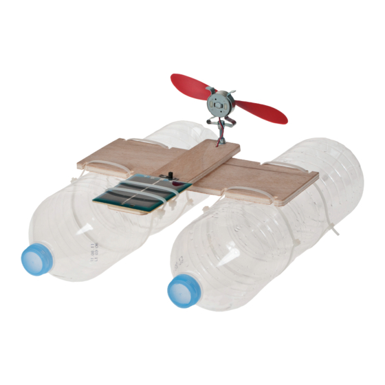
S o l a r - C a t a m a r a n
Necessary tools:
Pencil and ruler
Fretsaw
Pillar drill
Screwdriver
Spanner M4
Drills 4,5 8mm diameter
Sandpaper,file
Craft knife or chisel
Side cutters
Soldering iron, solder
All purpose glue or waterproofPVA
Varnish or paints ,brush
The OPITEC range of projects is not intended as play toys for
young children.They are teaching aids for young people
learning the skills of Craft, Design and Technology.These
projects should only be undertaken and tested with the
guidance of a fully qualified adult.
The finished projects are not suitable to give to children
under 3 years old. Some parts can be swallowed. Danger of
1
220x150x6 Base
1
Ø23-27 Motor holder
1
M4 x30 Fixing
2
M4 Fixing
2
M4 Fixing
1
M4 Fixing
1
Ø24 Drive
1
19x6 Circuit
1
500 Circuit
1
1,5V/300mA Power source
1
130 Drive
6
3,5x345 Fixing
Please Note
suffocation!
1
2
3
4
5
6
7
8
9
10
11
12
1
Advertisement

Related Manuals for Opitec 111.714


Summary of Contents for Opitec 111.714
- Page 1 All purpose glue or waterproofPVA Varnish or paints ,brush Please Note The OPITEC range of projects is not intended as play toys for young children.They are teaching aids for young people learning the skills of Craft, Design and Technology.These projects should only be undertaken and tested with the guidance of a fully qualified adult.
- Page 2 INSTRUCTIONS 1. Trace the pattern (s. Seite 5) on the plywood sheet (1) and cut out the shapes. Cut and drill PART A and PART B. Sand to finish Teile (A) und (B) bohren, aussägen und verschleifen. 2. Mark and cut out the cable chanel with a craft knife or a chisel (B) between the 4 mm hole and the sitch ( Pattern broken line ) 3.
- Page 3 INSTRUCTIONS 5. Insert the solar motor (7) in the spring clip mounting(2) with the shaft facing forward (2) and adjust the motor so that the cables lead downwards 6. Use the connections with the solar cell (10) to fix it in place. The cell must be with the active side uppermost 7.
- Page 4 INSTRUCTIONS 9. Thread the motor cable through the free 4 mm hole in part B in the direction of the switch. Finally glue part B on to part A. Make sure that the cable does not slide out of the canal . Leave glue to dry well 10.
- Page 5 INSTRUCTIONS Patterns M 1:1 D111714#1...
Need help?
Do you have a question about the 111.714 and is the answer not in the manual?
Questions and answers