Advertisement
Quick Links
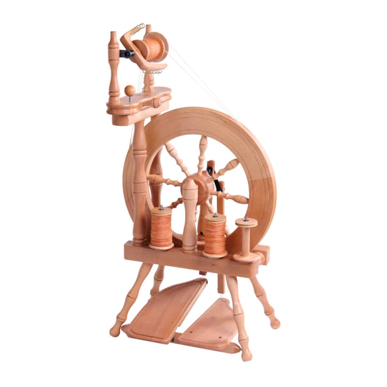
TRAVELLER SPINNING WHEEL
SINGLE DRIVE
Ashford Handicrafts Limited
Factory and Showroom: 415 West Street
PO Box 474, Ashburton 7700 New Zealand
Telephone 64 3 308 9087
Email: sales@ashford.co.nz Internet: www.ashford.co.nz
INSTRUCTIONS
DOUBLE DRIVE
Ashford Guarantee
Thank you for purchasing this Ashford product. In the unlikely event there is
any fault in manufacture, please contact the dealer you purchased it from. To
validate the guarantee, please go to www.ashford.co.nz/product-registration
or email us.
TVDTS-TVDTD120820V1
Advertisement

Subscribe to Our Youtube Channel
Related Manuals for Ashford Traveller Single Drive


Summary of Contents for Ashford Traveller Single Drive
- Page 1 Ashford Guarantee Factory and Showroom: 415 West Street Thank you for purchasing this Ashford product. In the unlikely event there is PO Box 474, Ashburton 7700 New Zealand any fault in manufacture, please contact the dealer you purchased it from. To Telephone 64 3 308 9087 validate the guarantee, please go to www.ashford.co.nz/product-registration...
-
Page 2: Tools Required
ASSEMBLY INSTRUCTIONS FOR THE ASHFORD TRAVELLER SPINNING WHEEL - Single and Double Drive - Before commencing, please read these instructions of colour and grain. For a silky smooth matt finish, completely, identify the parts and note the use the Ashford Wax Finish to enhance the natural assembly sequence. - Page 3 Real Scale Hardware List...
- Page 4 Check the holes in the base for the maiden bar supports are on the left hand side. Wax the steel rods in the treadle rail. Locate the treadle rail into the holes in 2 legs. Check the treadle rail rotates freely. Then tap these legs to the bottom of the holes.
- Page 5 Secure the 4 legs with screws. Turn the base and legs over. Secure the rear wheel Rear supports with bolts and barrel nuts. This will be tightened after the next step. Note the hole in one wheel support is right through. This is the rear support.
- Page 6 Check the alignment of the holes for the crank. Tighten the bolts from underneath. Place the wheel in position and insert the crank shaft. Align the hole in the crank shaft with the groove of the hub. Check the wheel is parallel in the centre of the base and the wheel supports are tight...
- Page 7 Rotate the hub pin until it is a firm fit in the slot in the hub. Then tap the hub pin through the hub and crank. Hint: Use a Lazy Kate pin as a punch to avoid damaging the hub. Slide the inner shell of the conrod universal joint onto the crank until it clicks into the groove.
- Page 8 Insert the front conrod into the large slot in left hand treadle board. 1. Hold the conrod joint with one hand on either side of the treadle board. 2. With both hands, turn the conrod joint a ¼ turn. 3. Stretch and slide it into the small slot and turn it back a ¼...
- Page 9 SINGLE DRIVE Step 13 - 25 For Single Drive only. For Double Drive go to Step 26. Thread 12 hooks into the flyer. Secure the 2 hinges to the maiden bar. Note the position of the slot in the hinge. Assemble the flyer unit.
- Page 10 Check the angle of nylon bearings and then secure the maid uprights with screws and washers. Do not overtighten. The maid uprights may be twisted to remove the bobbin. Thread the screw eye into the side of the maiden bar. Slide a bobbin onto the flyer and the flyer into the bearings.
- Page 11 Attach the brake band. Thread it through the screw eye and then tie the springs as illustrated. 45cm (18”) Put the brake band over the grooved end of the bobbin. Do not over stretch springs. Apply a drop of light oil to the bearings.
- Page 12 Secure the flyer unit to the top rail with 2 screws. These will be tightened shortly. Move the flyer unit until the wheel and flyer are aligned as pictured. Then tighten the screws and position the drawing pin directly beneath the drive band adjusting knob to prevent it marking the wood.
- Page 13 Ratios : You may find it easier to spin a finer yarn if your flyer rotates faster. To change ratio simply move the drive belt to a smaller flyer pulley and retension the drive belt. Oil all points on the Spinning Wheel before use as illustrated.
- Page 14 DOUBLE DRIVE Step 26 - 37 For Double Drive only. For Single Drive go to Step 13. Thread 12 hooks into the flyer. Secure the 2 hinges to the maiden bar. Note the position of the slot in the hinge. Assemble the flyer unit.
- Page 15 Check the angle of nylon bearings and then secure the maid uprights with screws and washers. Do not overtighten. The maid uprights may be twisted to remove the bobbin. Thread the screw eye into the side of the maiden bar. Slide a bobbin onto the flyer followed by the whorl.
- Page 16 Use the brake band option when you spin with scotch tension. Otherwise store it as illustrated. Secure the top rail to the maiden bar supports with 2 screws. Secure the flyer unit to the top rail with 2 screws. These will be tightened shortly.
- Page 17 Tie the threading hook to the front maid upright with tape. Check the end of the adjusting knob is not protruding beneath the maiden bar. Then wrap the drive belt around the wheel, around the large flyer pulley, back around the wheel and around the small bobbin pulley.
- Page 18 Ratios : You may find it easier to spin a finer yarn if your flyer rotates faster. To change ratio simply move the drive belt to a smaller flyer pulley and retension the drive belt. 10.5 : To achieve 14:1, wrap the brake band over the flyer pulley and the drive belt around the bob-...
- Page 19 If the drive band falls off easily: SINGLE DRIVE DOUBLE DRIVE Check all bolts are tight. How to insert the polyurethane conrod joints into the conrod. *This has been pre-assembled in the factory.
- Page 20 Ashford Handicrafts Limited Factory and Showroom: 415 West Street PO Box 474, Ashburton 7700 New Zealand Telephone 64 3 308 9087 Email: sales@ashford.co.nz Internet: www.ashford.co.nz...
Need help?
Do you have a question about the Traveller Single Drive and is the answer not in the manual?
Questions and answers