Advertisement
Quick Links
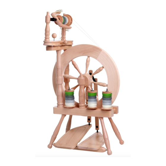
TRAVELLER SPINNING WHEEL
Ashford Handicrafts Limited
Factory and Showroom: 415 West Street
PO Box 474, Ashburton 7700 New Zealand
Telephone 64 3 308 9087 Facsimile 64 3 308 8664
Email: sales@ashford.co.nz Internet: www.ashford.co.nz
INSTRUCTIONS
DOUBLE DRIVE
Ashford Guarantee
Thank you for purchasing this Ashford product. In the unlikely event there is
any fault in manufacture we will replace the item. To validate our guarantee
please visit our website or write to us.
TVDTD25072016V10
Advertisement

Related Manuals for Ashford DOUBLE DRIVE


Summary of Contents for Ashford DOUBLE DRIVE
- Page 1 Ashford Guarantee Factory and Showroom: 415 West Street Thank you for purchasing this Ashford product. In the unlikely event there is PO Box 474, Ashburton 7700 New Zealand any fault in manufacture we will replace the item. To validate our guarantee Telephone 64 3 308 9087 Facsimile 64 3 308 8664 please visit our website or write to us.
-
Page 2: Tools Required
Before commencing, please read these instructions of colour and grain. For a silky smooth matt finish, completely, identify the parts and note the assem- use the Ashford Wax Finish to enhance the natural bly sequence. colours and character of this timber. - Page 3 Real Scale Hardware List...
- Page 4 Thread 12 hooks into the flyer. Secure the 2 hinges to the maiden bar. Note the position of the slot in the hinge. Assemble the flyer unit. Check the shape of the nylon bearing on each maid upright, then insert into the correct hole.
- Page 5 Check the angle of nylon bearings and then se- cure the maid uprights with screws and wash- ers. Do not overtighten. The maid uprights may be twisted to remove the bobbin. Thread the screw eye into the side of the maiden bar. Slide a bobbin onto the flyer followed by the whorl.
- Page 6 Attach the brake band. Thread it through the screw eye and then tie the springs as illustrat- 32cm (12 ¾”) Use the brake band option when you spin with scotch tension. Otherwise store it as il- lustrated. Check the holes in the base for the maiden bar supports are on the left hand side.
- Page 7 Locate the treadle rail into the holes in 2 legs. Check the treadle rail rotates freely. Then tap these legs to the bottom of the holes. Tap the other legs to the bottom of the holes. Secure the 4 legs with screws.
- Page 8 Turn the base and legs over. Secure the rear wheel supports with bolts and barrel nuts. Rear This will be tightened after the next step. Note the hole in one wheel support is right through. This is the rear support. Secure the front wheel supports with bolts and barrel nuts.
- Page 9 Check the alignment of the holes for the crank. Tighten the bolts from underneath. Place the wheel in posi- tion and insert the crank shaft. Align the hole in the crank shaft with the groove of the hub. Check the wheel is parallel in the centre of the base and the wheel supports are tight against the hub.
- Page 10 Rotate the hub pin until it is a firm fit in the slot in the hub. Then tap the hub pin through the hub and crank. Hint: Use a Lazy Kate pin as a punch to avoid damaging the hub. Slide the inner shell of the conrod universal joint onto the crank until...
- Page 11 Insert the front conrod into the large slot in left hand treadle board. 1. Hold the conrod joint with one hand on ei- ther side of the treadle board. 2. With both hands, turn the conrod joint a ¼ turn. 3.
- Page 12 Secure the top rail to the maiden bar supports with 2 screws. Secure the flyer unit to the top rail with 2 screws. These will be tightened shortly. Move the flyer unit until the wheel and middle flyer pulley are aligned. Then tighten the screws and position the drawing pin directly beneath the...
- Page 13 Check the end of the adjusting knob is not protruding beneath the maiden bar. Then wrap the drive belt around the wheel, around the large flyer pulley, back around the wheel and around the small bobbin pulley. Tie drive belt and cut off the extra.
- Page 14 Oil all points on the Spinning Wheel before use as illustrated. How to insert the polyurethane conrod joints into the conrod. *This has been pre-assembled in the factory.
- Page 15 Solutions Does not pull yarn in Large Small whorl whorl Drive band ten- 1-2mm sion is too loose. Tighten the tension knob 1-2mm. Yarn breaks Drive band tension 1-2mm is too tight. Loosen the tension knob 1-2mm. Hard to treadle...
- Page 16 Drive band falls off easily Strange sounds Ashford Handicrafts Limited Factory and Showroom: 415 West Street PO Box 474, Ashburton 7700 New Zealand Telephone 64 3 308 9087 Facsimile 64 3 308 8664 Email: sales@ashford.co.nz Internet: www.ashford.co.nz...
Need help?
Do you have a question about the DOUBLE DRIVE and is the answer not in the manual?
Questions and answers