Advertisement
Quick Links
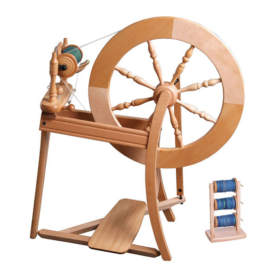
ASHFORD TRADITIONAL SPINNING WHEEL
Ashford Handicrafts Limited
Factory and Showroom: 415 West Street
PO Box 474, Ashburton 7700 New Zealand
Telephone 64 3 308 9087 Facsimile 64 3 308 8664
Email: sales@ashford.co.nz Internet: www.ashford.co.nz
INSTRUCTIONS
SINGLE DRIVE
Ashford Guarantee
Thank you for purchasing this Ashford product. In the unlikely event there is any
fault in manufacture we will replace the item. To validate our guarantee please
visit our website or write to us.
TDSW110618V11
Advertisement

Related Manuals for Ashford TDSW110618V11


Summary of Contents for Ashford TDSW110618V11
- Page 1 Ashford Guarantee Factory and Showroom: 415 West Street Thank you for purchasing this Ashford product. In the unlikely event there is any PO Box 474, Ashburton 7700 New Zealand fault in manufacture we will replace the item. To validate our guarantee please Telephone 64 3 308 9087 Facsimile 64 3 308 8664 visit our website or write to us.
-
Page 2: Tools Required
Before commencing, please read these instructions of colour and grain. For a silky smooth matt finish, completely, identify the parts and note the use the Ashford Wax Finish to enhance the natural assembly sequence. colours and character of this timber. - Page 3 Real Scale Hardware List...
- Page 4 Assemble the Lazy Kate. Note - the holes with countersunk holes on each upright face inwards. Thread 12 hooks into the flyer. Assemble the flyer unit. Check the shape of the nylon bearing on each maid upright, wax the dowel ends, then insert into the correct hole.
- Page 5 Check the angle of the nylon bearings. Then secure the maid uprights with screws and washers. Do not overtighten. The maid uprights may be twisted to remove the bobbin. Position the drawing pin directly beneath the drive band adjusting knob. Place the bobbin, small end first, onto the flyer.
- Page 6 Attach the brake band. Thread it through the screw eye and then tie the springs as illustrated. 37cm (14¾) Put the brake band over the grooved end of the bobbin. Do not over stretch the springs. Tie the threading hook to the front maid upright with tape.
- Page 7 Check the small hole is on the top of the side rails. Attach the side rails to the single leg with bolts and barrel nuts. Check the angle of the side rails and tighten.
- Page 8 Set the treadle assembly on the edge of a table. Insert the conrod joint into the large slot in the treadle rail. Note the crank bearing faces the back of the spinning wheel. Hold the conrod With both hands, joint with one hand turn the conrod on either side of the joint a ¼...
- Page 9 Wax the steel rods in the treadle rail. Loosely attach the wheel support to the side rails with bolts and barrel nuts. Then locate the treadle rail into the holes in the legs...
- Page 10 Check the angle of the single leg. Insert the crank shaft into the wheel support. Tighten every bolt extra firmly with the allen key. Place the wheel in position. Before placing the wheel in position, check the crank fits through the hole in the hub.
- Page 11 Align the wheel and hole in the crank shaft with the groove in the hub using a lazy kate wire. Carefully tap the hub pin through the hub and crank. Slide the inner shell of the conrod universal joint onto the crank until it clicks into the groove.
- Page 12 Attach the flyer unit to the side rails with 2 screws and washers, do not tighten yet. Move the flyer unit until the wheel and large flyer pulley are aligned. Then tighten the screws. Check the end of the adjusting knob is not protruding beneath the maiden bar.
- Page 13 How to insert the polyurethane conrod joints into the conrod. *This has been pre-assembled in the factory. Ashford Handicrafts Limited Factory and Showroom: 415 West Street PO Box 474, Ashburton 7700 New Zealand Telephone 64 3 308 9087 Facsimile 64 3 308 8664 Email: sales@ashford.co.nz Internet: www.ashford.co.nz...
Need help?
Do you have a question about the TDSW110618V11 and is the answer not in the manual?
Questions and answers