
Related Manuals for FiberHome CiTRANS R820


Summary of Contents for FiberHome CiTRANS R820
- Page 1 CiTRANS R820 Edge Router Hardware Description Version: A Code: MN000001856 FiberHome Telecommunication Technologies Co., Ltd. May 2014...
- Page 3 Please contact your local sales representative, service representative or distributor for any help needed at the contact information shown below. Fiberhome Telecommunication Technologies Co., Ltd. Address: No. 67, Guanggu Chuangye Jie, Wuhan, Hubei, China Zip code: 430073...
- Page 5 Legal Notice are trademarks of FiberHome Telecommunication Technologies Co., Ltd. (Hereinafter referred to as FiberHome) All brand names and product names used in this document are used for identification purposes only and are trademarks or registered trademarks of their respective holders.
-
Page 7: Preface
Preface Related Documentation Description Document Introduces the product's functions and features, protection CiTRANS R820 Edge Router principles, networking modes and applications, and Product Description technical specifications. Introduces the structure, functions, specifications, and CiTRANS R820 Edge Router technical parameters of the product's hardware... -
Page 8: Version
Version Description Version Initial version Intended Readers This manual is intended for the following readers: Planning and designing engineers Commissioning engineers Operation and maintenance engineers To utilize this manual, these prerequisite skills are necessary: IP/MPLS technology Data communication technology SDH communication theory Ethernet technology... -
Page 9: Conventions
Conventions Terminology Conventions Terminology Convention FiberHome CiTRANS R820 Edge Router CiTRANS R820 FiberHome e-Fim OTNM2000 Element Management OTNM2000 System Router System Control Unit SCUS1 Router System Control Unit2 SCUS2 Router System Control Unit3 SCUS3 MSS1 Octal Port Ethernet Mixed Interface Card... -
Page 11: Table Of Contents
Contents Preface........................I Related Documentation ...................I Version ......................II Intended Readers ...................II Conventions ....................III Cabinet......................1-1 19-inch Cabinet ................1-2 1.1.1 Model ................1-2 1.1.2 Appearance ..............1-2 1.1.3 Cabinet Structure.............1-3 1.1.4 Indicator ................1-6 1.1.5 Typical Layout ..............1-8 21-inch Cabinet ................1-9 1.2.1 Model ................1-10 1.2.2 Appearance ..............1-10 1.2.3 Cabinet Structure............1-11 1.2.4... - Page 12 Technical Parameters ..............2-10 AC/DC Power Adapter .................3-1 Model ....................3-2 Function ..................3-2 Appearance...................3-2 Technical Parameters ..............3-3 Subrack.......................4-1 Subrack Structure ................4-2 Fan Control Card ................4-3 4.2.1 Model ................4-3 4.2.2 Function ................4-3 4.2.3 Appearance ..............4-3 4.2.4 Intelligent Fan Control ............4-4 4.2.5 Indicator ................4-5 4.2.6 Safety Sign ..............4-5 4.2.7...
- Page 13 Overview ..................6-2 Power Cable and Earth Ground Cable..........6-3 6.2.1 Cabinet Power Cable ............6-3 6.2.2 Cabinet Protection Earth Ground Cable......6-5 6.2.3 Subrack Power Cable ............6-6 6.2.4 Subrack Protection Earth Ground Cable ......6-7 Alarm Cable...................6-8 6.3.1 Alarm Cable of the Head of Row Cabinet......6-9 6.3.2 Subrack Alarm Cable .............6-10 E1 Cable ..................6-12...
- Page 15 Figures Figure 1-1 Appearance of a 19-inch Cabinet ...........1-3 Figure 1-2 Exploded View of a 19-inch Cabinet ..........1-4 Figure 1-3 Main Components of a 19-inch Cabinet and Their Names....1-5 Figure 1-4 Indicators on the 19 inch Cabinet ..........1-6 Figure 1-5 Typical Layout of the 19-inch Cabinet ..........1-9 Figure 1-6 Appearance of a 21-Inch Cabinet (300 mm in Depth)....1-11...
- Page 16 Figure 5-9 Panel of the PWRS1 Card............5-23 Figure 6-1 Cabinet Power Cable ..............6-3 Figure 6-2 Cabinet Protection Earth Ground Cable..........6-5 Figure 6-3 Structure of the Subrack Power Cable ..........6-6 Figure 6-4 Subrack Protection Earth Ground Cable .........6-8 Figure 6-5 Alarm Cable of the Head of Row Cabinet........6-9 Figure 6-6 Alarm Cable of a Subrack ............6-11 Figure 6-7...
- Page 17 Tables Table 1-1 Size of Each Type of 19-inch Cabinet ..........1-2 Table 1-2 19-inch Cabinet Model ..............1-2 Table 1-3 Names and Functions of Major Components in a 19-inch Cabinet...1-6 Table 1-4 Indicators on the 19-inch Cabinet ...........1-8 Table 1-5 Size of Each Type of 21-inch Cabinet ..........1-9 Table 1-6 21-inch Cabinet Model ..............1-10 Table 1-7...
- Page 18 Panel of the PWRS1 Card............5-23 Table 5-20 Technical Parameters of the PWRS1 Card ........5-24 Table 6-1 Cables and Connectors Used by the CiTRANS R820 .....6-2 Table 6-2 Models of the Cabinet Power Cable..........6-3 Table 6-3 Connection Method of the Cabinet Power Cable......6-4 Table 6-4 Technical Parameters of the Cabinet Power Cable ......6-4...
- Page 19 Table 6-12 Technical Parameters of the Alarm Cable of the Head of Row Cabinet..................6-10 Table 6-13 Pinout and Wiring of A Straight-through Cable ......6-11 Table 6-14 Connection Method of the Subrack Alarm Cable......6-12 Table 6-15 Technical Parameters of the Subrack Alarm Cable .......6-12 Table 6-16 Pinout and Wiring Scheme of the E1 Cable ........6-13 Table 6-17...
-
Page 21: Cabinet
A cabinet is used to carry subracks and power distribution panel (PDP) and implements functions, such as wiring of cables and optical cables, dust-proof, and Electromagnetic Interference (EMI). The CiTRANS R820 can be installed in a standard 19-inch or 21-inch cabinet. -
Page 22: 19-Inch Cabinet
1600 600 600 2000 600 600 2200 600 600 2600 600 600 1.1.1 Model The CiTRANS R820 subrack can be installed on four types of 19-inch cabinets, as listed in Table 1-2. Table 1-2 19-inch Cabinet Model Cabinet Model 4.102.596 4.102.597... -
Page 23: Cabinet Structure
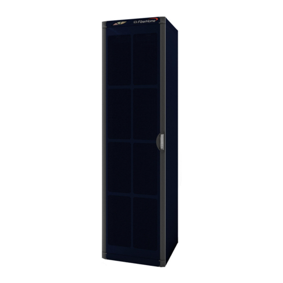
1 Cabinet Figure 1-1 Appearance of a 19-inch Cabinet 1.1.3 Cabinet Structure A 19-inch cabinet consists of the cabinet body and cabinet doors. Figure 1-2 shows the exploded view of the cabinet. Version: A... - Page 24 CiTRANS R820 Edge Router Hardware Description (1) Front door (2) Left side door (3) Rear door (4) Cabinet body (5) Right side door Figure 1-2 Exploded View of a 19-inch Cabinet The cabinet body mainly consists of four vertical mounting flanges, the cabinet top, the cabinet base, as well as slide rails and connecting pieces between the vertical mounting flanges.
-
Page 25: Figure 1-3 Main Components Of A 19-Inch Cabinet And Their Names
1 Cabinet (1) Mounting hole for the top-connection bent (2) Wiring hole at the cabinet top angle bracket (3) Cabinet-top ventilation hole (4) Cabinet Indicator (5) ESD protection earth ground fastener (6) Mounting hole on the vertical mounting flanges (7) Wiring hole at the cabinet bottom (8) Front door (9) Side door (10) Button on the side door... -
Page 26: Indicator
CiTRANS R820 Edge Router Hardware Description Table 1-3 lists names and functions of major components in a 19-inch cabinet. Table 1-3 Names and Functions of Major Components in a 19-inch Cabinet Component S.N. Name Function Mounting hole for the top-... - Page 27 1 Cabinet Version: A...
-
Page 28: Typical Layout
If the cabinet is not fully occupied, arrange subracks from the bottom up and reserve the upper space for capacity expansion. Figure 1-5 shows the typical layout of the CiTRANS R820 in 19-inch cabinets. Version: A... -
Page 29: 21-Inch Cabinet
Figure 1-5 Typical Layout of the 19-inch Cabinet 21-inch Cabinet The CiTRANS R820 can be installed in a 21-inch cabinet. Four types of 21-inch cabinets are available, as shown in Table 1-5. Table 1-5 Size of Each Type of 21-inch Cabinet... -
Page 30: Model
CiTRANS R820 Edge Router Hardware Description 1.2.1 Model The CiTRANS R820 subrack can be installed on four types of 21-inch cabinets, as listed in Table 1-6. Table 1-6 21-inch Cabinet Model Cabinet Model 4.102.589 4.102.590 21-inch cabinet 4.102.591 4.102.592 1.2.2 Appearance Figure 1-6 shows the appearance of a 21-inch cabinet (300 mm in depth). -
Page 31: Cabinet Structure
1 Cabinet Figure 1-6 Appearance of a 21-Inch Cabinet (300 mm in Depth) 1.2.3 Cabinet Structure The 21-inch cabinet (300 mm in depth) consists of the cabinet body and cabinet doors, as shown in Figure 1-7. Version: A 1-11... -
Page 32: Figure 1-7 Exploded View Of A 21-Inch Cabinet (300 Mm In Depth)
CiTRANS R820 Edge Router Hardware Description (1) Front door (2) Cabinet body (3) Rear door Figure 1-7 Exploded View of a 21-Inch Cabinet (300 mm in Depth) The cabinet body mainly consists of four vertical mounting flanges, the cabinet top, the cabinet base, as well as slide rails and connecting pieces between the vertical mounting flanges. -
Page 33: Figure 1-8 General Structure Of A 21-Inch Cabinet (300 Mm In Depth)
1 Cabinet (1) Wiring hole at the cabinet top (2) Cabinet Indicator (3) ESD protection earth ground fastener (4) Rear door (5) Wiring channel (6) Wiring hole at the cabinet bottom (7) Mounting hole on the vertical mounting (8) Front door flanges (9) Mounting hole for the top-connection bent (10) Cabinet-top ventilation hole... -
Page 34: Indicator
CiTRANS R820 Edge Router Hardware Description Table 1-7 lists names and functions of major components in a 21-inch cabinet (300 mm in depth). Table 1-7 Names and Functions of Major Components in a 21-inch Cabinet (300 mm in depth) Component... -
Page 35: Typical Layout
1 Cabinet (1) Red indicator (2) Yellow indicator (3) Green indicator Figure 1-9 Indicators on the 21 inch Cabinet The 21-inch cabinet provides three indicators. Table 1-8 describes the status of each indicator. Table 1-8 Indicators on the 21-inch Cabinet Description Indicator Status... -
Page 36: Figure 1-10 Typical Layout Of The 21-Inch Cabinet
If the cabinet is not fully occupied, arrange subracks from the bottom up and reserve the upper space for capacity expansion. Figure 1-10 shows the typical layout of the CiTRANS R820 in 21-inch cabinets. Figure 1-10 Typical Layout of the 21-inch Cabinet... -
Page 37: Pdp
The following introduces the PDP used by the CiTRANS R820. Model Function Appearance Front Panel Connection Terminals and Switches Lightning Protection Module Technical Parameters Version: A... -
Page 38: Model
CiTRANS R820 Edge Router Hardware Description Model The CiTRANS R820 uses the PDP250B. The hardware codes of the PDP is 3.000.073-1FB (applicable to a 19-inch cabinet) or 3.000.073-2FB (applicable to a 21-inch cabinet). Function Major functions of this PDP250B are as follows:... -
Page 39: Front Panel
2 PDP Figure 2-1 Appearance of the PDP250B Front Panel On the front panel of the PDP250B, the positions of automatic circuit breakers and lightning protection failure indicator (FAIL) are marked, as shown in Figure 2-2. Figure 2-2 Front Panel of the PDP250B Version: A... -
Page 40: Connection Terminals And Switches
CiTRANS R820 Edge Router Hardware Description Connection Terminals and Switches The following introduces functions of connection terminals and switches on the PDP250B. 2.5.1 Connection Terminal Board After removing the front panel of the PDP250B, you can see that components (such as connection terminals and buzzers) are distributed on the panel of the PDP250B, as shown in Figure 2-3 and Table 2-1. -
Page 41: Switches
2 PDP Table 2-1 Components on the PDP250B Connection Terminal Board (Continued) Terminal & Jumper Component Description Subrack alarm convergence connector XS13, XS14, XS1 Automatic circuit breaker of each branch power SW1 1 to SW1 3 supply SW2 1 to SW2 3 Lightning protection module sockets (working in XS11, XS12 active/standby mode) -
Page 42: Power Terminals
CiTRANS R820 Edge Router Hardware Description 2.5.3 Power Terminals Table 2-2 describes the input terminals of the external power supply. Table 2-2 Input Terminals of the External Power Supply Description Connection Terminal SW1, SW2 -48 V input terminals of the external power supply... -
Page 43: Other Terminals
2 PDP Table 2-3 Output Terminals of the Branch Power Supply Description Connection Terminal SW1 1 to SW1 3 SW2 1 to SW2 3 -48 V output terminals of the branch power supply 0V_1 to 0V_3 terminals of XS2 0V_1 to 0V_3 terminals of XS5 0 V output terminals of the branch power supply 2.5.4 Other Terminals... -
Page 44: Lightning Protection Module
CiTRANS R820 Edge Router Hardware Description Table 2-4 Subrack Alarm Input Terminals (Continued) Interface Type Terminal Name Function Terminals 1 to 8 are defined in XS13 Network cable When the equipment alarm sequence as connector output is connected to this... - Page 45 2 PDP Figure 2-5 Lightning Protection Module Table 2-5 Definitions of Pins on the Plug of the Lightning Protection Module Description Definition Protection earth 1, 14 For ground protection. ground Discharges the lightning surge to the ground, and is Level 1 lightning 2, 3, 15, 16 connected to the level 2 lightning protection 0 V protection 0 V...
-
Page 46: Technical Parameters
CiTRANS R820 Edge Router Hardware Description Technical Parameters Table 2-6 PDP250B Technical Parameters Performance Specification Item Input voltage range (V) -38 to -58 Input Maximum input current 50 per branch Output voltage range (V) -37 to -59 Output Output branch... - Page 47 2 PDP Table 2-6 PDP250B Technical Parameters (Continued) Performance Specification Item A 8/20us 2kA test surge current is imposed in the positive and negative directions between the external Common mode power input terminals -48 V and PE and between 0 V protection and PE.
-
Page 49: Ac/Dc Power Adapter
AC/DC Power Adapter The following introduces the AC/DC power adapter used by the CiTRANS R820. Model Function Appearance Technical Parameters Version: A... -
Page 50: Model
CiTRANS R820 Edge Router Hardware Description Model The following AC/DC power adapter models are used by the CiTRANS R820, including PTSP000146, PTSP000147, PTSP000151, and PTSP000153. The AC/ DC power adapter model is configured according to the project requirements. Function The AC/DC power adapter configured for the CiTRANS R820 converts the AC power (110 V to 230 V) to the DC power (-48 V). -
Page 51: Technical Parameters
3 AC/DC Power Adapter Figure 3-1 Appearance of the AC/DC Power Adapter Technical Parameters Table 3-1 Technical Parameters of the AC/DC Power Adapter Performance Specification Item Input voltage range (V) 154 to 286 Input voltage frequency (Hz) 47 to 63 Input AC input system Three-wire single-phase... -
Page 53: Subrack
Subrack The subrack is the core unit of the CiTRANS R820. It accommodates various cards. The following introduces the structure and technical parameters of the CiTRANS R820 subrack. Subrack Structure Fan Control Card Slot Allocation Access Bandwidth Safety Sign Technical Parameters... -
Page 54: Subrack Structure
CiTRANS R820 Edge Router Hardware Description Subrack Structure Figure 4-1 shows the structure of a CiTRANS R820 subrack. Table 4-1 describes each component of the subrack. (1) Mounting ear (2) Earth ground pole and earth label (3) Fan control card... -
Page 55: Fan Control Card
CiTRANS R820. 4.2.1 Model The model of the fan control card used by the CiTRANS R820 is 2.200.816. 4.2.2 Function The fan control card is used for air cooling the equipment. The OTNM2000 can control the operating status of fans to ensure that the equipment runs normally and efficiently at a stable ambient temperature. -
Page 56: Intelligent Fan Control
4.2.4 Intelligent Fan Control Overview The CiTRANS R820 fan control card works in either intelligent or manual mode. Intelligent mode: The fan rotation speed is automatically adjusted according to the temperature reported by each card of the equipment. Manual mode: The fan unit rotates according to the speed set in the OTNM2000. -
Page 57: Indicator
4 Subrack 4.2.5 Indicator Two indicators are available on the panel of the fan control card, as described in Table 4-2. Table 4-2 Indicators on the Fan Control Card Sign Meaning Description Abbreviation Color ON: The fan control card is powered Operating Green OFF: The fan control card is... -
Page 58: Slot Allocation
Figure 4-3 Slot Allocation of a Subrack Slots 01, 04, and 05 in the CiTRANS R820 subrack are permanently allocated to the SCUS1/2/3, PWRS1, and fan control card. Slots 02 and 03 are service slots where various types of service cards can be inserted. -
Page 59: Safety Sign
4 Subrack Safety Sign Table 4-5 describes meanings of safety signs on the subrack. Table 4-5 The Subrack Safety Signs Sign Meaning ESD protection sign. This sign reminds the maintenance staff to wear the ESD protection wrist strap during operations to prevent possible damages to the equipment caused by the human body electrostatic. -
Page 61: Card
Card The following introduces functions and panels of cards on the CiTRANS R820. Overview Introduction to Cards Version: A... -
Page 62: Overview
(2) Card name (3) Card interface (4) Latch (5) Captive screw Figure 5-1 Appearance of a Card Table 5-1 lists dimensions of cards used on the CiTRANS R820. Table 5-1 Dimensions of Cards Panel dimensions (HWD, mm) Card SCUS1/2/3 20386198... -
Page 63: Structure
5 Card 5.1.2 Structure The CiTRANS R820 uses three types of cards. The following illustrates three views of each type of cards. Service Card Figure 5-2 shows the three views of a service card using the E1S1 card as an example. -
Page 64: Figure 5-3 Three Views Of The Core Switch Card
CiTRANS R820 Edge Router Hardware Description Figure 5-3 Three Views of the Core Switch Card Power Card Figure 5-4 shows the three views of a power card. Figure 5-4 Three Views of the Power Card Version: A... -
Page 65: Classification
5 Card 5.1.3 Classification Cards on the CiTRANS R820 can be classified by function into the service cards, core switch cards, and power cards. Table 5-2 describes how these cards are classified. Table 5-2 Classification of Cards Type Meaning Card... -
Page 66: Mapping Between Cards And Slots
CiTRANS R820 Edge Router Hardware Description Figure 5-5 Positioning of Cards in the System 5.1.5 Mapping between Cards and Slots Table 5-3 describes the mapping between cards and slots. Table 5-3 Mapping between Cards and Slots Slot Type Meaning Card... -
Page 67: Introduction To Cards
02, 03 E1S1 Introduction to Cards The following introduces the models, major functions, service processing capability, panels, slots, and technical parameters of cards on the CiTRANS R820. 5.2.1 SCUS1/SCUS2/SCUS3 The following introduces the models and functions of the SCUS1/SCUS2/SCUS3 cards. - Page 68 CiTRANS R820 Edge Router Hardware Description Collects and distribute single-card configurations, alarms, and performance data. Service access and switching functions Provides a switching capacity of 26G. Processes packets, for example, identifies, terminates, encapsulates, and discards packets and performs unicast and multicast processing for packets.
-
Page 69: Figure 5-6 Front Panel Of The Scus1/Scus2/Scus3 Card
5 Card Figure 5-6 Front Panel of the SCUS1/SCUS2/SCUS3 Card Table 5-4 describes the panel of the SCUS1/SCUS2/SCUS3 card. Table 5-5 describes the interfaces or terminals on the panel. Version: A... - Page 70 CiTRANS R820 Edge Router Hardware Description Table 5-4 Panel of the SCUS1/SCUS2/SCUS3 Card Description Indicator/Interface/Button Non-critical alarm indicator (yellow) OFF: The card does not have any minor alarm, or all the minor alarms are filtered. ON: The card has a minor alarm.
- Page 71 5 Card Table 5-4 Panel of the SCUS1/SCUS2/SCUS3 Card (Continued) Description Indicator/Interface/Button Ethernet debugging COM interface, COM/MC equipment room monitoring M/C interface The auxiliary terminal interface, used to take charge of the auxiliary terminal board. Inputs/outputs clock signals. CKIO Inputs/outputs time signals. Data switching interface GE / FE1 to GE / Interface type:...
- Page 72 CiTRANS R820 Edge Router Hardware Description Table 5-5 Definitions of Interfaces or Terminals on the Panel of the SCUS1/SCUS2/SCUS3 (Continued) Note 1 Diagram Description Name Interface Positive terminal of the Ethernet data output Negative terminal of the Ethernet data output...
- Page 73 5 Card Table 5-5 Definitions of Interfaces or Terminals on the Panel of the SCUS1/SCUS2/SCUS3 (Continued) Note 1 Diagram Description Name Interface Negative terminal of the lightning LALM- protection alarm signal input Positive terminal of the lightning LALM+ protection alarm signal input External clock output CLKOP CLKON...
-
Page 74: Table 5-7 Ge Optical Interface Specifications Of The Scus1/Scus2/Scus3 Card
CiTRANS R820 Edge Router Hardware Description Table 5-7 and Table 5-8 list the interface specifications of the SCUS1/SCUS2/ SCUS3 card. Table 5-7 GE Optical Interface Specifications of the SCUS1/SCUS2/SCUS3 Card Specification Item 1000BAS- 1000BASE- 1000BASE- 1000BAS- 1000BASE- Optical interface type... -
Page 75: Mss1/Mss2/Mss3
5 Card 5.2.2 MSS1/MSS2/MSS3 The following introduces the models and functions of the MSS1, MSS2, and MSS3 cards. Model MSS1 model: 2.200.814 MSS2 model: 2.201.343 MSS3 model: 2.201.344 Functions Provides the GE/FE optical interfaces. Transforms the -48 V voltage to the 3.3 V or 1.5 V voltage and provides the voltage to each module on the card. -
Page 76: Figure 5-7 Panel Of The Mss1/Mss2/Mss3 Card
CiTRANS R820 Edge Router Hardware Description Figure 5-7 Panel of the MSS1/MSS2/MSS3 Card Table 5-10 describes the panel of the MSS1/MSS2/MSS3 card. 5-16 Version: A... - Page 77 5 Card Table 5-10 Panel of the MSS1/MSS2/MSS3 Card Indicator/Interface/But- Description Operating indicator (green) Blinking quickly: The card is operating normally. ON or OFF: The card is not operating normally. (ON generally means a poor communication between the card and the OTNM2000.) Critical alarm indicator (red) OFF: The card does not have any critical or major alarm, or all the...
-
Page 78: Table 5-12 Ge Optical Interface Specifications Of The Mss1/Mss2/Mss3
CiTRANS R820 Edge Router Hardware Description Table 5-12 GE Optical Interface Specifications of the MSS1/MSS2/MSS3 Card (Continued) Specification Item Target distance (km) 0.55 Mean launched power -9.5 to 0 -8 to -3 -2 to 3 -2 to 5 -2 to 5... -
Page 79: E1S1
5 Card The interfaces provided by the E1S1 card comply with ITU-T Y.1413, IETF PW3 emulation draft, and MEF8. Transmits data with low delay, meeting the requirements of real-time services. Provides 75-ohm and 120-ohm E1 interfaces and supports soft switching of the interface types based on the configuration on the OTNM2000. - Page 80 CiTRANS R820 Edge Router Hardware Description Figure 5-8 Panel of the E1S1 Card Table 5-15 describes the panel of the E1S1 card. Table 5-15 Panel of the E1S1 Card Indicator/Interface/- Description Button Operating indicator (green) Blinking quickly: The card is operating normally.
- Page 81 5 Card Table 5-15 Panel of the E1S1 Card (Continued) Indicator/Interface/- Description Button Non-critical alarm indicator (yellow) The card does not have any minor alarm, or all the minor alarms are filtered. ON: The card has a minor alarm. Inputs or outputs 16 lines of 2 Mbit/s signals. Applicable Slot The E1S1 card can be inserted to slot 02 or 03.
-
Page 82: Pwrs1
CiTRANS R820 Edge Router Hardware Description Table 5-17 Interface Specifications of the E1S1 Card (Continued) Specification Item Peak voltage of a space (no pulse) (V) 00.237 00.3 Nominal pulse width (ns) Ratio of the amplitudes of positive and negative pulses at the center of a pulse 0.95 to 1.05... -
Page 83: Table 5-19 Panel Of The Pwrs1 Card
5 Card Panel Description Figure 5-9 shows the panel of the PWRS1 card. Figure 5-9 Panel of the PWRS1 Card Table 5-19 describes the panel of the PWRS1 card. Table 5-19 Panel of the PWRS1 Card Description Indicator/Interface Power output indicator (green) ACTA/ACTB ON: The power output is normal. -
Page 84: Table 5-20 Technical Parameters Of The Pwrs1 Card
CiTRANS R820 Edge Router Hardware Description Table 5-20 Technical Parameters of the PWRS1 Card Item Specification Weight (kg) Dimensions (H W D) (mm) 41 26 223 Maximum power consumption (W) Voltage (V) 40 to -60 Under-voltage protection point (V) -362... -
Page 85: Cables
Cables The following introduces the cables and connectors used by the CiTRANS R820. Overview Power Cable and Earth Ground Cable Alarm Cable E1 Cable Network Cable Optical Fiber Jumper Version: A... -
Page 86: Overview
CiTRANS R820 Edge Router Hardware Description Overview Table 6-1 lists the cables and connectors used by the CiTRANS R820. Table 6-1 Cables and Connectors Used by the CiTRANS R820 Cable Type Usage Cable Name Cable Model 3.696.093 (blue) 3.696.094 (black) -
Page 87: Power Cable And Earth Ground Cable
6 Cables Power Cable and Earth Ground Cable Power cables used by the CiTRANS R820 include the cabinet power cables and subrack power cables. Earth ground cables used by the CiTRANS R820 include the cabinet protection earth ground cables and subrack protection earth ground cables. - Page 88 CiTRANS R820 Edge Router Hardware Description Connection Method Table 6-3 describes how the cabinet power cable is connected. Table 6-3 Connection Method of the Cabinet Power Cable Cable Name Terminal Connected to Naked wire PE terminal of XS4 on the PDP...
-
Page 89: Cabinet Protection Earth Ground Cable
6 Cables 6.2.2 Cabinet Protection Earth Ground Cable The following introduces the model, usage, structure, connection method, and technical parameters of the cabinet protection earth ground cable. Model The model of the cabinet protection earth ground cable is 3.696.044. Usage The cabinet protection earth ground cable connects the earth ground point of the cabinet to the protection earth ground of the PDP. -
Page 90: Subrack Power Cable
CiTRANS R820 Edge Router Hardware Description Table 6-6 Technical Parameters of the Cabinet Protection Earth Ground Cable Item Specification Cable type Multi strand single core flexible cable Yellow/green Color Maximum current (A) Conductor cross-sectional area (mm 6.2.3 Subrack Power Cable The following introduces the model, usage, structure, connection method, and technical parameters of the subrack power cable. -
Page 91: Subrack Protection Earth Ground Cable
6 Cables Connection Method Table 6-7 describes how the subrack power cable is connected. Table 6-7 Connection Method of the Subrack Power Cable Connected to Cable Name Terminal Any branch switch on the PDP Blue wire Subrack power Blue wire 0 V terminal of the XS2/XS5 on the PDP cable Connector post... -
Page 92: Alarm Cable
Multi strand single core flexible cable Yellow/green Color Maximum current (A) Conductor cross-sectional area (mm Alarm Cable Alarm cables used by the CiTRANS R820 includes the alarm cable of the head of row cabinet and the subrack alarm cables. Version: A... -
Page 93: Alarm Cable Of The Head Of Row Cabinet
6 Cables 6.3.1 Alarm Cable of the Head of Row Cabinet The following introduces the model, usage, structure, connection method, and technical parameters of the alarm cable of the head of row cabinet. Model The model of the alarm cable of the head of row cabinet is 3.696.135. Usage The alarm cable of the head of row cabinet connects the PDP to the head of row cabinet. -
Page 94: Subrack Alarm Cable
CiTRANS R820 Edge Router Hardware Description Table 6-11 Connection Method of the Alarm Cable of the Head of Row Cabinet Cable Name Terminal Connected to Three-core D-type connector XPB1 on the PDP Alarm cable of the head of row cabinet... - Page 95 6 Cables Figure 6-6 Alarm Cable of a Subrack As shown in Figure 6-7, both ends of the subrack alarm cable are RJ-45 connectors. Figure 6-7 RJ-45 Connector Table 6-13 describes the color-coding scheme of a straight-through cable are connected. Table 6-13 Pinout and Wiring of A Straight-through Cable Pin on the Local End...
-
Page 96: E1 Cable
Model of the 120 E1 cable: 409000040 Usage An E1 cable can transmit 16 channels of E1 signals. It connects the E1 interface of the E1S1 to the DDF and inputs/outputs E1 signals. The CiTRANS R820 uses the 75 and 120 E1 cables. 6-12... - Page 97 6 Cables Structure On the equipment side, a 64-pin E1 straight bus end connector is used to connect the E1 cable to the 2 Mbit/s interface. This connector is prepared before delivery of the equipment. The other end of the E1 cable is connected to the DDF, and the connector must be prepared on site.
-
Page 98: Network Cable
Connected to 64-pin E1 straight bus end connector E1 interface on the E1S1 card in a subrack Naked wire Network Cable The following introduces network cables used by the CiTRANS R820. 6.5.1 Network Cable Between the OTNM2000 and the Equipment Model 3.695.095 (straight-through cable) -
Page 99: Ethernet Service Cable
6 Cables Connection Method OTNM2000 monitoring cables (straight-through cables and cross-over cables) are connected as follows: Cross-over cable: One end of the cross-over cable is connected to the F / AUX port on the SCUS1/2/3 card, and the other end is connected to the network adapter port of the computer where the OTNM2000 is installed. -
Page 100: Clock And Time Cables
Interface Type Name Cable Model Communication cable - 8-core CAT-5 Ethernet service RJ-45 connector twisted pair - 24 AWG cable 6.5.3 Clock and Time Cables The following introduces clock cables and time cables used by the CiTRANS R820. 6-16 Version: A... - Page 101 6 Cables Model Model of the 75 clock cable: 409000060 Model of the 120 clock cable: 409000059 Model of the time cable: 3.695.458 Usage The clock cable is used to transmit clock synchronization signals. The clock cable is used to transmit time synchronization signals. Structure Figure 6-11 shows the appearance of the 75 ohm and 120 ohm clock cable.
- Page 102 CiTRANS R820 Edge Router Hardware Description Table 6-20 Pinout and Wiring Scheme of the 120 ohm Clock Cable (Continued) RJ-45 Connector Cable Color Coaxial Cable Definition Blue Twisted-pair cable 2 White / Blue Green White / Brown Brown Table 6-21 defines the pinouts and wiring scheme of the 75 ohm clock cable.
- Page 103 6 Cables Table 6-22 Pinout and Wiring Scheme of the Time Cable (Continued) RJ-45 Connector Cable Relationship Color Blue / White A pair Blue Brown / White A pair Brown Connection Method Table 6-23 describes how the external clock cable is connected. Table 6-23 Connection Method of the External Clock Cable Terminal...
-
Page 104: Optical Fiber Jumper
CiTRANS R820 Edge Router Hardware Description Optical Fiber Jumper The following introduces optical fiber jumpers used by the CiTRANS R820. Model The CiTRANS R820 uses the following types of optical fiber jumpers: Model of the LC/PC optical fiber jumper: OFC-LC/PC-LC/PC-S-20... - Page 105 6 Cables Figure 6-14 FC/PC Optical Fiber Jumper Connection Method The LC/PC-LC/PC optical fiber jumper is used inside a cabinet, whereas LC/PC-FC/ PC and LC/PC-SC/PC optical fiber jumpers are used for connection between the equipment to the ODF. Technical Parameters Table 6-26 lists technical parameters of optical fiber jumpers.
-
Page 107: Appendix A Card Name And Number List
Appendix A Card Name and Number List Table A-1 summarizes the names and numbers of cards. Table A-1 Names and Numbers of the Cards Card Type Card Number Card Name Router System Control Unit SCUS1 2.200.813 Router System Control Unit2 SCUS2 2.201.342 Router System Control Unit3... -
Page 109: Appendix B Size, Weight, And Power Consumption
Appendix B Size, Weight, and Power Consumption Table B-1 Mechanical Size and Power Consumption Dimensions (H W D) Weight (kg) Power consumption (W) Item (mm) Subrack 44.4 447 223 SCUS1 20 38 198 SCUS2 20 386 198 SCUS3 20 386 198 MSS1 20 192 198 MSS2... -
Page 111: Appendix C Interfaces
The following introduces interfaces of the CiTRANS R820 cards. Optical Interface Optical interfaces on the panel of a CiTRANS R820 optical interface card are classified into the RX optical interfaces for inputting optical signals and TX optical interface for outputting optical signals. The LC optical connector is used. - Page 112 CiTRANS R820 Edge Router Hardware Description Table C-1 Description about the RJ-45 Connector on the Panel of the SCUS1/2/3 Card Note 1 Diagram Description Interface Name Positive terminal of the Ethernet data output Negative terminal of the Ethernet data output...
-
Page 113: E1 Interface
DDF and inputs/outputs E1 signals. The 75 and 120 E1 cables can be used to connect E1 interfaces on the CiTRANS R820. The E1S1 card of the CiTRANS R820 provides E1 interfaces. Figure C-1 shows a 64-pin E1 interface. - Page 114 CiTRANS R820 Edge Router Hardware Description Figure C -1 E1 Interface For definitions of pins on the 75 or 120 E1 interface, see the Installation Guide. Version: A...
-
Page 115: Appendix D Indicators
The following introduces the status and meaning of each indicator on the CiTRANS R820. Indicators on the Cabinet Three indicators are available on the lintel of the CiTRANS R820 cabinet door. Table D-1 describes the status of each indicator. Table D-1... -
Page 116: Indicators On Cards
CiTRANS R820 Edge Router Hardware Description Table D-2 Indicators on the Fan Control Card (Continued) Meaning Description Indicator OFF: The fan control card does not have any alarm. Indicators on Cards Indicators on a card indicate the operating status and alarm status of the card. - Page 117 Appendix D Indicators Table D-4 Indicators on the Panel of the SCUS1/2/3 Card (Continued) Meaning Description Indicator Blinking (green): The management plane data is MCC communication available on the optical line. indicator Blinking (green): The control plane data is available SCC communication on the optical line.
-
Page 119: Appendix E Abbreviations
Appendix E Abbreviations Attachment Circuit Access Control List Automatic Protection Switching Address Resolution Protocol Autonomous System Automatically Switched Optical ASON Network Asynchronous Transfer Mode Boundary Clock Backup Designated Router Bidirectional Forwarding Detection Border Gateway Protocol Building Integrated Timing Supply BITS Best Master Clock Board Management Unit Bridge Protocol Data Unit... - Page 120 CiTRANS R820 Edge Router Hardware Description Designated Intermediate System Denial of Service Designated Router DSCP Differentiated Services Code Point Data Terminating Entity End-to-end Transparent Clock E2ETC External Border Gateway Protocol EBGP Equal-Cost Multi-Path ECMP Ethernet in the First Mile Electromagnetic Compatibility...
- Page 121 Appendix E Abbreviations Intermediate System to Intermediate IS-IS System Internet Service Provider International Telecommunication Union ITU Telecommunication ITU-T Standardization Sector Independent VLAN Learning Layer 2 Virtual Private Network L2VPN Layer 3 Virtual Private Network L3VPN Link Aggregation Control Protocol LACP Link Aggregation Group Label Distribution Protocol LSDB...
- Page 122 CiTRANS R820 Edge Router Hardware Description Maximum Transmission Unit Network Provider Edge None Stop Forwarding Network Time Protocol Operation, Administration and Maintenance Ordinary Clock Optical Distribution Frame Orthogonal Frequency Division OFDM Multiplex Open Systems Interconnection Open Shortest Path First OSPF...
- Page 123 Appendix E Abbreviations Serial Number SNCP Subnet Connection Protection Sequence Number Packet Synchronous Optical Network SONET Strict Priority Shortest Path First Service Router Synchronization Status Message Synchronous Transport Module Shared VLAN Learning Transparent Clock Time Division Multiplexing Tag Protocol Identifier TPID Tributary Protection Switching Uninterruptible Power Supply...
- Page 125 Product Documentation Customer Satisfaction Survery Thank you for reading and using the product documentation provided by FiberHome. Please take a moment to complete this survey. Your answers will help us to improve the documentation and better suit your needs. Your responses will be confidential and given serious consideration.
- Page 126 12. Additional comments about our documentation or suggestions on how we can improve: Thank you for your assistance. Please fax or send the completed survey to us at the contact information included in the documentation. If you have any questions or concerns about this survey please email at edit@fiberhome.com.cn...
Need help?
Do you have a question about the CiTRANS R820 and is the answer not in the manual?
Questions and answers