Table of Contents
Advertisement
Quick Links
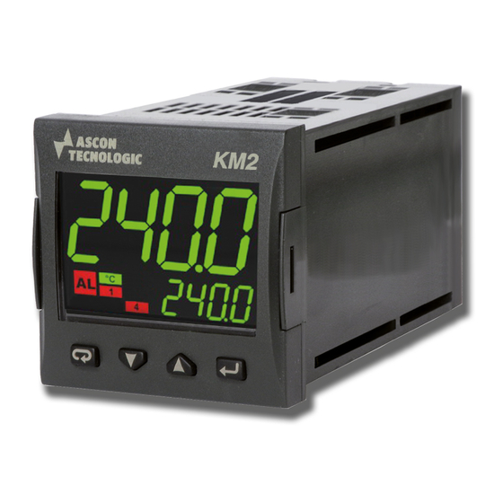
KM2
CONTROLLER AND
MINI-PROGRAMMER WITH
HEATER BREAK DOWN ALARM
Engineering Manual
Code : ISTR-MKM2ENG01 - Vr. 1.0 (ENG)
Ascon Tecnologic S.r.l.
Viale Indipendenza 56, 27029 Vigevano (PV) - ITALY
Tel.: +39 0381 69871/FAX: +39 0381 698730
www.ascontecnologic.com
e-mail: info@ascontecnologic.com
1.
OUTLINE DIMENSIONS (mm)
1.1
Mounting requirements
This instrument is intended for permanent installation, for
indoor use only, in an electrical panel which encloses the
rear housing, exposed terminals and wiring on the back.
Select a mounting location having the following characteristics:
1. It should be easily accessible;
2. There is minimum vibrations and no impact;
3. There are no corrosive gases;
4. There are no water or other fluids (i.e. condensation);
5. The ambient temperature is in accordance with the
operative temperature (0... 50°C);
6. The relative humidity is in accordance with the instrument
specifications (20... 85%);
The instrument can be mounted on panel with a maximum
thickness of 15 mm.
When the maximum front protection (IP65) is desired, the
optional gasket must be mounted.
1.2
Dimensions
1.2.1
Controller with non removable terminals
48
11
PV
AT
63.3
Ascon Tecnologic - KM2 Line - ENGINEERING MANUAL - PAG. 1
1.2.2
Removable terminals
Screw removable terminals
40
18.85
1.3
Panel cutout
2.
ELECTRICAL CONNECTIONS
2.1
General notes about wiring
1. Do not run input wires together with power cables.
2. External components (like zener barriers, etc.) connected
between sensor and input terminals may cause errors in
measurement due to excessive and/or not balanced line
resistance or possible leakage currents.
3. When a shielded cable is used, it should be connected at
one point only.
4. Pay attention to the line resistance; a high line resistance
may cause measurement errors.
2.2
Wiring diagram
DI2 (note)
Analogue input
2 wires
12 VDC
(note)
PV
Transmitter
mV, V
3 wires
12 VDC
(note)
14
PV
Transmitter
Passive 4... 20 mA
Spring removable terminals
15.5
8.3
26
65 mm min.
45
+0.6
Out1
RS485
Out3
Thermocouple
mA
Relay Out 1:
Relay Out 2:
SSR Out 1, 2:
Out1:
SSR Out 3:
Note: Terminal 4 can be porogrammed
as Digital Input, Logic output or
Pt1000/NTC/PTC
Pt100
Transmitter PWS
40
15
8.3
DI1
Out2
C.T. input
50 mA AC
Power
AC/DC
supply
4 (4) A/250 VAC
2 (1) A/250 VAC
10 Vdc/15 mA
0/4... 20 mA, 0/2... 10V
12 Vdc/20 mA
Advertisement
Table of Contents

Related Manuals for Ascon tecnologic KM2


Summary of Contents for Ascon tecnologic KM2
- Page 1 0/4... 20 mA, 0/2... 10V SSR Out 3: 12 Vdc/20 mA Note: Terminal 4 can be porogrammed Transmitter as Digital Input, Logic output or Passive 4... 20 mA Pt1000/NTC/PTC Pt100 Transmitter PWS Ascon Tecnologic - KM2 Line - ENGINEERING MANUAL - PAG. 1...
-
Page 2: Thermocouple Input
V and mV Input Logic status 0: 0... 3 VDC. 2.3.8 Current transformer input C.T. input 50 mA AC Input impedance: > 1 MΩ for mV Input, 500 kΩ for Volt Input. Ascon Tecnologic - KM2 Line - ENGINEERING MANUAL - PAG. 2... -
Page 3: Serial Interface
V output: 0/2... 10 V, galvanically isolated, RL min.: 500Ω. 2.4.2 Output 2 (OP2) Relay Output Contact rating: • 2 A /250 V cosj = 1; • 1 A /250 V cosj = 0.4. Operation: 1 x 10 Ascon Tecnologic - KM2 Line - ENGINEERING MANUAL - PAG. 3... -
Page 4: Power Supply
Storage temperature: -30... +70°C (-22... +158°F); Humidity: 20... 85% RH, not condensing. Electromagnetic compatibility and safety requirements Compliance: • EMC Directive (EN 61326-1), • Safety Directive (EN 61010-1); Installation category: II; Pollution category: 2. Ascon Tecnologic - KM2 Line - ENGINEERING MANUAL - PAG. 4... -
Page 5: Configuration Procedure
We define all the above described conditions as “Standard Note: The group selection is cyclic as well as the selection Display”. of the parameters in a group. Ascon Tecnologic - KM2 Line - ENGINEERING MANUAL - PAG. 5... - Page 6 0... 5 V linear; 0 mA = 0 mBar and 20 mA = -1000 mBar (vacuum). 1... 5 V linear; 0.10 0... 10 V linear; 2.10 2... 10 V linear. Ascon Tecnologic - KM2 Line - ENGINEERING MANUAL - PAG. 6...
- Page 7 Alarm acknowledge (ACK) [status]; Hold of the measured value [status]; Stand by mode of the instrument [status]. When the contact is closed the instrument oper- ates in stand by mode; Manual mode; Ascon Tecnologic - KM2 Line - ENGINEERING MANUAL - PAG. 7...
- Page 8 Notes: 1. When two or more outputs are programmed in the Point) of one step. The selection is cyclic: same way, these outputs are driven in parallel. SP -> SP2 -> SP3 -> SP4. Ascon Tecnologic - KM2 Line - ENGINEERING MANUAL - PAG. 8...
- Page 9 +16 Sensor break (burn out); P.HLd Program hold indicator; +32 Overload on Out 3 (short circuit on the Out 3). P.uit Program wait indicator; For more details see [17] o1.AL parameter. Ascon Tecnologic - KM2 Line - ENGINEERING MANUAL - PAG. 9...
- Page 10 +2 Latched alarm (manual reset); +4 Acknowledgeable alarm; +8 Relative alarm not active at Set Point change. Example: Setting Ab1 equal to 5 (1 + 4) the alarm 1 will be Ascon Tecnologic - KM2 Line - ENGINEERING MANUAL - PAG. 10...
- Page 11 Range: -1999 to [36] AL2H engineering units. 1... 9999 seconds. Note: The alarm goes ON only when the alarm condition persists for a time longer than [31] AL1d time but the reset is immediate. Ascon Tecnologic - KM2 Line - ENGINEERING MANUAL - PAG. 11...
- Page 12 Absolute low alarm; HiAb Absolute high alarm; LHAo Absolute band alarm with alarm indication out of the band; LHAi Absolute band alarm with alarm indication inside the band; SE.br Sensor break. Ascon Tecnologic - KM2 Line - ENGINEERING MANUAL - PAG. 12...
- Page 13 The load can be: independent (not managed by an output Range: • When two control actions (heat & cool) are pro- of the KM2) or managed by an output of the KM2. In the grammed: first condition (independent), the instrument will perform the PID (heat and cool);...
- Page 14 This parameter reduces the overshoot usually present at Range: -100.0... +100.0%. instrument start up or after a Set Point change and it will be active only in this two cases. Ascon Tecnologic - KM2 Line - ENGINEERING MANUAL - PAG. 14...
- Page 15 Notes: 1. A [81] A.SP change produces the following actions: is lower or equal to SS.tH parameter. • When [82] SP.rt = SP - the remote Set Point Ascon Tecnologic - KM2 Line - ENGINEERING MANUAL - PAG. 15...
- Page 16 – Sixth zone SP = 210 + 50 = 260°C. Changing the SP of the master unit, all the other slave units will immediately change their operative Set Point. Ascon Tecnologic - KM2 Line - ENGINEERING MANUAL - PAG. 16...
- Page 17 An event can drive an output and make an of rise for positive Set Point change) and [85] SPd action during one or more specific program steps. Ascon Tecnologic - KM2 Line - ENGINEERING MANUAL - PAG. 17...
- Page 18 Available: When [91] Pr.F is different from nonE, 10. 1 0 [100] Pr.S2 is different from oFF and 01. 1 0 [105] Pr.S3 is different from oFF. 11. 1 0 Range: 0.00... 99.59 time units. Ascon Tecnologic - KM2 Line - ENGINEERING MANUAL - PAG. 18...
- Page 19 Available: When [91] Pr.F is different from nonE. parameters [66] tcH, [67] rcG and [68] tcc. Range: run Program Run; HoLd Program Hold; Program reset. Note: This parameter allows to manage program execution by a parameter. Ascon Tecnologic - KM2 Line - ENGINEERING MANUAL - PAG. 19...
- Page 20 ON/OFF control is selected); ct.on CT measure during ON; ct.on CT measure during ON; ct.OF CT measure during OFF; ct.OF CT measure during OFF; ct.iS Instantaneous CT measurement. ct.iS Instantaneous CT measurement. Ascon Tecnologic - KM2 Line - ENGINEERING MANUAL - PAG. 20...
- Page 21 Power ON the instrument will re-start in ment is turned ON divided by 24. manual mode with the same power used prior to Total worked hours: Number of hours that the the power down. Ascon Tecnologic - KM2 Line - ENGINEERING MANUAL - PAG. 21...
- Page 22 In order to exit from configuration parameter procedure, proceed as follows: • Push button. • Push button for more than 10 s. The instrument returns to the “Standard display”. Ascon Tecnologic - KM2 Line - ENGINEERING MANUAL - PAG. 22...
- Page 23 - SP - - AL2 - - Pb - - SP3 - - ti - - A.SP - A.SP - AL1 - - td - - Aut.r - A 10 Aut.r Ascon Tecnologic - KM2 Line - ENGINEERING MANUAL - PAG. 23...
-
Page 24: Operative Modes
10 seconds, the instrument goes back to display” push the button for more than 5 s. the “standard display” and the new value of the last selected parameter will be lost. Ascon Tecnologic - KM2 Line - ENGINEERING MANUAL - PAG. 24... -
Page 25: Automatic Mode
Standard display. the desired value; 3. Push no buttons for more than 5 second or push the button. In both cases the instrument stores the new value and Ascon Tecnologic - KM2 Line - ENGINEERING MANUAL - PAG. 25... -
Page 26: Display Management
Event 1 = ON shutter closed Time P.End Out 1 = H.rEG (heating output) Out 2 = P.Et1 (program event 1) Out 3 = P.run (program running) Pr.E1and Pr.E2 = 10.10 Ascon Tecnologic - KM2 Line - ENGINEERING MANUAL - PAG. 26... -
Page 27: Manual Mode
5. When the instrument is swapped from stand by to auto modes, the instrument will start automatically the alarm masking, the soft start functions and the auto-tune (if programmed). Ascon Tecnologic - KM2 Line - ENGINEERING MANUAL - PAG. 27... -
Page 28: General Notes
The appliance (or the product) must be fees or charge for Ascon Tecnologic, except in the event of disposed of separately in compliance alternative agreements. with the local standards in force on waste disposal. Ascon Tecnologic - KM2 Line - ENGINEERING MANUAL - PAG. 28... - Page 29 Output active used as PWS for TX; out3 Output 3 (digital output 3); I/O 3 function out3 IO3. F dG2c Digital input 2 driven by contact; dG2U Digital input 2 driven by voltage. Ascon Tecnologic - KM2 Line - ENGINEERING MANUAL - PAG. 29...
- Page 30 +8 Heater Break Down; +16 Sensor Break; +32 Overload on output 3. Direct action; Reverse action; Out 1 action o1Ac dir.r Direct with reversed LED; ReU.r Reverse with reversed LED Ascon Tecnologic - KM2 Line - ENGINEERING MANUAL - PAG. 30...
- Page 31 +8 Heater Break Down; +16 Sensor Break; +32 Overload on output 3. Direct action; Reverse action; Out 3 action o3Ac dir.r Direct with reversed LED; ReU.r Reverse with reversed LED. Ascon Tecnologic - KM2 Line - ENGINEERING MANUAL - PAG. 31...
- Page 32 Alarm 2 enabled in stand by mode; AL2o in over or under range conditions Alarm 2 enabled in out of range conditions; Alarm 2 enabled in stand by mode and out of range conditions. Ascon Tecnologic - KM2 Line - ENGINEERING MANUAL - PAG. 32...
- Page 33 ON/OFF control with neutral zone. output are configured cont PID (heat and/or); Control type when the outputs are On.FA ON/OFF asymmetric hysteresis; configured for heating or cooling On.FS ON/OFF symmetric hysteresis. Ascon Tecnologic - KM2 Line - ENGINEERING MANUAL - PAG. 33...
- Page 34 0.01... 99.99 (100.00 = inF) engineering units per minute SP. u Point change (ramp UP) Rate of rise for NEGATIVE Set 0.01... 99.99 (100.00 = inF) engineering units per minute SP. d Point change (ramp DOWN) Ascon Tecnologic - KM2 Line - ENGINEERING MANUAL - PAG. 34...
- Page 35 114 Pr. E 4 Events of the 4 group 00.00... 11.11 (0: Event OFF, 1: Event ON) 00.00 Program reset; 115 Pr. S t Program status Program start; HoLd Program hold. Ascon Tecnologic - KM2 Line - ENGINEERING MANUAL - PAG. 35...
- Page 36 1... 999 (E.U.) management Display always ON; 123 di. S t Display Timeout 0.1... 99.59 (mm.ss). Filter on the displayed Filter disabled; 124 fiLd value 0.1... 20.0 (E.U.). 125 Reserved Ascon Tecnologic - KM2 Line - ENGINEERING MANUAL - PAG. 36...
- Page 37 1... 999 (A) Threshold of the working Threshold not used; 135 h. J ob hours 0... 9999 hours. 136 t. J ob Worked days (not resettable) 0 0... 9999 days Ascon Tecnologic - KM2 Line - ENGINEERING MANUAL - PAG. 37...
- Page 38 Adjust Low Offset -300... +300 (E.U.) 139 AH. P Adjust High Point From (AL.P + 10) to 9999 engineering units 9999 140 AH. o Adjust High Offset -300... +300 Ascon Tecnologic - KM2 Line - ENGINEERING MANUAL - PAG. 38...
- Page 39 Ascon Tecnologic - KM2 Line - ENGINEERING MANUAL - PAG. 39...
- Page 40 Ascon Tecnologic - KM2 Line - ENGINEERING MANUAL - PAG. 40...
Need help?
Do you have a question about the KM2 and is the answer not in the manual?
Questions and answers