Table of Contents
Advertisement
Quick Links
WINE CONTROLLER
1/16 DIN - 48 x 48
Model KM1E
Q u i c k G u i d e • I S T R - F K M 1 E - E N G 0 1
viale Indipendenza 56, 27029 - Vigevano (PV) - ITALY
Tel.: +39 0381 698 71, Fax: +39 0381 698 730
internet site:
www.ascontecnologic.com
E-mail:
sales@ascontecnologic.com
MODEL CODE
The Hardware resources are identified by the following Model Code.
Model:
KM1E A B C D E F G H
Line
Power Supply
24Vac (-25... +12%) or 24Vdc (-15... +25%)
100... 240 Vac (-15... +10%)
Input + Ditigal input1
PT100, PT1000, mA + Digital Input 1
PTC, NTC, mA + Digital Input 1
Output OP1 (control output)
Relay (1 SPST NO, 4 A/250 Vac)
Output OP2 (control output)
None
Relay SPST NO 2 A/250 Vac (resistive load)
Output OP3 (alarm output)
None
Relay SPST NO 2 A/250 Vac (resistive load) selectable if Output 1 is present
Output OP4 (configurable)
Digital I/O (see the Electrical Connections paragraph for details)
PARAMETERS SETTING
KM1E
Press for 2 seconds
2 s
on the key
The KM1E-xDRRRDxx controller is pre-configured (default
configuration) for wine applications where there is the
need to cool or reheat in thermostatic mode (on/off with
hysteresis) a tank with a PT100 probe in mono relay
output (Heat and Cool on OP1).
Parameter setting
Confirm value and pass to the next parameter
Increases the displayed value
Decreases the displayed value
To exit the parameters configuration procedure, press
for 3 seconds or wait for the end of the delay
(about 10 seconds)
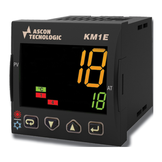
CONTROLLER DISPLAY
KM1E
KM1E
Heat mode
Cool mode
The controller action type can be identified by the color of the upper display (measurement):
Red:
Heat mode only
Green: Cool mode only
Orange: The controller responds to temperature changes and selects the appropriate control mode
by operating the appropriate control output and displaying the setpoint to be reached.
The numbered red LEDs indicate, when lighted, the active (on) state of the corresponding relay output.
DECLARATION OF CONFORMITY AND
ube
MANUAL RETRIEVAL
KM1E is a panel mounting, Class II instrument. It has been
designed with compliance to the European Directives.
All information about the controller use can be found in the
Engineering Manual: ISTR-MKM_-ENG0x ("x" is the revision).
The Declaration of Conformity and the manual of the controller
can be downloaded (free of charge) from the web-site:
www.ascontecnologic.com
Once connected to the web-site, search: KM1E
then click on KM1E.
In the lower part of the product page (in any language) is present
the download area with links to the documents available for the
controller (in the available languages).
Warning!
- Whenever a failure or a malfunction of the device may cause
dangerous situations for persons, things or animals, please
remember that the plant must be equipped with additional
devices which will guarantee safety.
- We warrant that the products will be free from defects in material and
workmanship for 18 months from the date of delivery. Products
and components that are subject to wear due to conditions of
use, service life and misuse are not covered by this warranty.
Disposal
The appliance (or the product) must be disposed of
separately in compliance with the local standards in
force on waste disposal.
KME
Serial Communications
TTL Modbus
B
RS485 Modbus
L
Terminal Type
H
Standard (screw type non removable terminal blocks)
C
With plug-in screw type terminal blocks
With plug-in clamp type terminal blocks
D
With plug-in terminal blocks (fixed part only)
P
D
R
E
-
R
Model Code example: KM1E-LDRRRD-E
KM1E controller for Wine applications
F
- Power supply: 24Vac/dc,
-
- Inputs: PT1000 or 4... 20 mA +1 Digital Input,
R
- 3 Relay Outputs (OP1: Alarm, OP2: Cold, OP3 Alarme),
- Confiigurable OP4: Digital Input 2 or Transmitter power supply,
G
- TTL Port,
D
- Removable screw type terminals.
KM1E
KM1E
KM1E
KM1E
Automatic Heat/Cool
selection
DISPLAY AND KEYS
Unit
KM1E
(°C/°F)
Alarm
active
Manual
mode
Output
LEDs
Operator Mode
Control Mode
Access to:
- Setpoint adjustment
Confirm and go to
(SP display)
Next parameter
- Setpoint validation
Increase the displayed
Access to:
value
- Setpoint adjustment
Decrease the displayed
Access to:
value
- Setpoint adjustment
Back to Operator mode
Access to:
Control mode toggle
(long pressure)
Displays the previous parameter
(Heat/Cool) (pressed for
in Control mode (short pressure)
more than 1 s)
ELECTRICAL CONNECTIONS
H
-
S
RS485
I
DI2 (note)
-
E
M
Analogue input
N
12 VDC
(note)
PV
4... 20 mA
2 wire transmitter
12 VDC
(note)
PV
4... 20 mA
3 wire transmitter
Pt1000/NTC/PTC
Parameters List (PASS: 30)
Group Param.
Description
Control mode selection
node
Measurement input type
sEns
inp
Decimal point position
dp
Digital input 1 function
diF1
Digital input 2 function
diF2
Digital Inputs Action
di. a
Key
function
Pan
usrb
Modbus address of the controller 1... 254
Add
ser
Modbus transmission speed
bAud
Several successive pressures on the
key allow the various groups of parameters to be scrolled.
A long pressure on the
key allows to exit the Configuration mode and return to the Operator mode
Parameters List (PASS: 20)
Param.
Description
reg
Operative mode selection
OPEr
stdy Standby
Set point 1
-1999... +9999 (Engineering Unit)
SP
Set point 2
-1999... +9999 (Engineering Unit)
SP2
Heat Hysteresis
0... 9999 (Engineering Unit)
HstH
Cool Hysteresis
0... 9999 (Engineering Unit)
HstC
Alarm 1 threshold (Low)
AL1L... AL1H
AL1
Alarm 2 threshold (High)
AL2L... AL2H
AL2
Decimal point position
0... 2
dP
Setpoint Low Limit
From 0 to the SPHL value
SPLL
Setpoint High Limit
From the value of SPLL to 1999
SPHL
0
Digital filter on the measured value
FiL
0.1... 20.0 s
Alarm 1 Hysteresis
0...9999 (Engineering Unit)
HAL1
Alarm 2 Hysteresis
0...9999 (Engineering Unit)
HAL2
Adjust Low Offset
-300...+300 (Engineering Unit)
Al. o
Note: Several successive pressures on the
key allow to scroll the available Control parameters.
m
Pressing no keys for 5 s, the controller automatically exits PASS20 menu and returns to the standard display and the current measurement.
DIMENSIONS
Process Value
Overall dimensions (L x H x D
max.
(in eng. units)
Autotune
Panel Cut-out (L x H):
in progress
(flashing)
Set Point
(auto mode)
Output Value
(manual mode)
Param. value or
State/Function
(Editing mode)
MOUNTING
1
1
OP1
OP2
OP3
OP4
(note)
Power
supply
mA
Note: Terminal 4 can be programmed as:
- Digital Input (DI2) connecting a free of
voltage contact between terminals 4 and 16;
- 0... 12 V SSR Drive Output (OP4) connecting
the load between terminals 4 and 16;
- 12 Vdc (20 mA) transmitter power supply
connecting the 2 wire transmitter between
terminals 4 and 1; for 3 wire transmitter connect
terminal 4 to transmitter power supply input and
Pt100
terminal 1 and 2 to transmitter signal output.
Value range or selection list
Default
selection
1
Heat or Cool on OP1 only,
2
Heat (OP1) or Cool (OP2),
1
3
Heat (OP1) and Cool (OP2),
Pt1
Pt100
Pt10 Pt1000
Pt1
4.20 4... 20 mA
0... 2
0
Stby Mode Standby (transition)
nonE
Stby2 Mode Standby (status)
HC.tr Chaud <-> Froid (transition)
nonE
HC.St Chaud <-> Froid (status)
0... 3
0
Stby Standby Mode
1H2C Heat <-> Cool toggle
Auto
HC.Sb Heat <-> Cool and
Auto <-> Standby
1
1200, 2400, 9600 baud,
9600
19.2, 38.4 kbaud
User
Value range or selection list
Default
selection
Auto,
reg
0
0
1
1
0
80
0
0
90
oFF
1.0
1
1
0
): 48 x 48 x 73... 99 mm
(1.89 x 1.89 x 2.78... 3.89 in.)
45 +0.6 x 45 +0.6 mm
(1.78 +0.023 x 1.78 +0.023 in.)
3
2
2
TERMINALS
DI1
Pin connector
1.4 mm max.
q
(0.055 in.)
L
Stripped wire
L:
5.5 mm
(0.21 in.)
Line
100... 240 Vac/
18... 28 Vac/
Neutral
20... 30 Vdc
User
Note
When only 1 output is
present, the controller
does not display the
node parameter.
It is fixed on "Mode 1"
See the manual for
details
If HC. S b: a 1 s pressure
toggles between
Heat <-> Cool mode.
A 5 s pressure puts the
controller in standby
Modbus RTU slave
Protocol
Note
stdy: Control action stopped
reg: Control action running
Advertisement
Table of Contents

Related Manuals for Ascon tecnologic Kube KM1E


Summary of Contents for Ascon tecnologic Kube KM1E
- Page 1 DIMENSIONS WINE CONTROLLER DECLARATION OF CONFORMITY AND DISPLAY AND KEYS Process Value MANUAL RETRIEVAL Overall dimensions (L x H x D ): 48 x 48 x 73... 99 mm 1/16 DIN - 48 x 48 max. (in eng. units) Unit (1.89 x 1.89 x 2.78...
- Page 2 CONTROLLER OPERATION DI1/DI2 Digital Input functions (pass = 30) Set Point Change KM1E KM1E KM1E KM1E KM1E KM1E KM1E Press the key (3 s) or wait for the 10s time out to store the new Set Point and return to Normal Mode Operative Set Point Modified Set Point The Setpoint temperature setting is made pressing for a long time on the arrow keys...
Need help?
Do you have a question about the Kube KM1E and is the answer not in the manual?
Questions and answers