Table of Contents
Advertisement
Quick Links
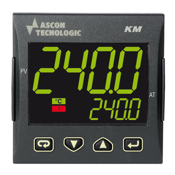
KM5P
CONTROLLER, PROGRAMMER
and SET POINT SETTER
Engineering Manual
21/11 - Code: ISTR_M_KM5P_E_00_--
Ascon Tecnologic S.r.l.
Viale Indipendenza 56, 27029 Vigevano (PV) - ITALY
Tel.: +39 0381 69871/FAX: +39 0381 698730
www.ascontecnologic.com
e-mail: info@ascontecnologic.com
1. OUTLINE DIMENSIONS (mm)
1.1
Mounting requirements
This instrument is intended for permanent installation, for
indoor use only, in an electrical panel which encloses the
rear housing, exposed terminals and wiring on the back.
Select a mounting location having the following characteristics:
1. It should be easily accessible;
2. There is minimum vibrations and no impact;
3. There are no corrosive gases;
4. There are no water or other fluids (i.e. condensation);
5. The ambient temperature is in accordance with the
operative temperature (0... 50°C);
6. The relative humidity is in accordance with the instrument
specifications (20... 85%);
The instrument can be mounted on panel with a maximum
thickness of 15 mm.
When the maximum front protection (IP65) is desired, the
optional gasket must be mounted (see "How to order"
paragraph for details).
1.2
Dimensions
1.2.1
Controller with non removable terminals
48
PV
AT
*
The controllers with universal power supply,
have the body long 63.3 mm
Ascon Tecnologic - KM5P Line - ENGINEERING MANUAL - PAG. 1
11
48 *
14
1.2.2
Removable terminals
Screw removable terminals
40
15.5
8.3
18.85
1.2.3
Panel cutout
45
+0.6
2. ELECTRICAL CONECTIONS
2.1
Wiring diagram
RS485
DI2 (note)
Analogue input
12 VDC
(note)
PV
Thermo-
mV, V
mA
4... 20 mA
couple
2 wire transmitter
12 VDC
(note)
PV
4... 20 mA
Pt1000/NTC/PTC
Pt100
3 wire transmitter
General notes about wiring
1. Do not run input wires together with power cables.
2. External components (like zener barriers, etc.) connected
between sensor and input terminals may cause errors in
measurement due to excessive and/or not balanced line
resistance or possible leakage currents.
3. When a shielded cable is used, it should be connected at
one point only.
4. Pay attention to the line resistance; a high line resistance
may cause measurement errors.
Spring removable terminals
40
26
65 mm min.
DI1
OP1
open
OP2
close
OP4
OP3
(note)
Line
Power
supply
Neutral
Note: Terminal 4 can be programmed as:
- Digital Input (DI2) connecting a dry contact
between terminals 4 and 16;
- 0... 12 V SSR Drive Output (OP4) connecting
the load between terminals 4 and 16;
- 12 Vdc (20 mA) transmitter power supply
connecting the 2 wire transmitter between
terminals 4 and 1; for 3 wire transmitter connect
terminal 4 to transmitter power supply input
and terminal 1 and 2 to transmitter signal output.
15
8.3
TERMINALS
Pin connector
1.4 mm max.
q
(0.055 in.)
L
Stripped wire
L:
5.5 mm
(0.21 in.)
Advertisement
Table of Contents

Related Manuals for Ascon tecnologic KM5P Series


Summary of Contents for Ascon tecnologic KM5P Series
- Page 1 4. Pay attention to the line resistance; a high line resistance may cause measurement errors. The controllers with universal power supply, have the body long 63.3 mm Ascon Tecnologic - KM5P Line - ENGINEERING MANUAL - PAG. 1...
-
Page 2: Thermocouple Input
Input 1 Input 2 Logic status 1: 6... 24 VDC; Logic status 0: 0... 3 VDC. Input impedance: > 1 MΩ for mV Input 500 kΩ for Volt Input. Ascon Tecnologic - KM5P Line - ENGINEERING MANUAL - PAG. 2... - Page 3 Output 2 (OP2) Note: Overload protected. Relay Output Contact rating: • 2 A /250 V cosj = 1; • 1 A /250 V cosj = 0.4. Operation: 1 x 10 Ascon Tecnologic - KM5P Line - ENGINEERING MANUAL - PAG. 3...
-
Page 4: Serial Interface
NOT supplied and the instrument can show the “ouLd” (Out 4 Overload) indication. Compliance: EMC directive (EN 61326-1), Safety directive (EN 61010-1); Installation category: II; Pollution category: 2. Ascon Tecnologic - KM5P Line - ENGINEERING MANUAL - PAG. 4... - Page 5 M = Removable spring terminals N = Removable terminals (the fixed part only) Note: For servomotor drive, both Output 2 and Output 3 codes must be selected as “M”. Ascon Tecnologic - KM5P Line - ENGINEERING MANUAL - PAG. 5...
-
Page 6: Configuration Procedure
NOTE VERY WELL: In all cases, the decimal figure of the less significant digit of the lower display is lit. We define all the above described conditions as “Standard Display”. Ascon Tecnologic - KM5P Line - ENGINEERING MANUAL - PAG. 6... -
Page 7: Parameters Configuration
2.10 2... 10 V linear. than the initial scale read-out in order to obtain a reverse read-out scaling. E.g.: 0 mA = 0 mBar and 20 mA = -1000 mBar (vacuum). Ascon Tecnologic - KM5P Line - ENGINEERING MANUAL - PAG. 7... - Page 8 2 will work in parallel makes parameter [24] O4F visible equal to nonE. with the button. Notes: 1. When [10] diF1 = 12, [11] diF2 setting is forced to Ascon Tecnologic - KM5P Line - ENGINEERING MANUAL - PAG. 8...
- Page 9 Program run indicator; when the instrument power supply goes OFF or P.Et1 Program Event 1; the internal watchdog starts. P.Et2 Program Event 2; or.bo Out-of-range or burn out indicator; Ascon Tecnologic - KM5P Line - ENGINEERING MANUAL - PAG. 9...
- Page 10 +16 Sensor break (burn out); +32 Overload on Out 4 (short circuit on OP4). P.FAL Power failure indicator; bo.PF Out-of-range, Burnout and Power failure For more details see [17] o1.AL parameter. Ascon Tecnologic - KM5P Line - ENGINEERING MANUAL - PAG. 10...
- Page 11 +8 Relative alarm not active at set point change. Example: Setting Ab1 equal to 5 (1 + 4) the alarm 1 will be “not active at power up” and “Acknowledgeable”. Ascon Tecnologic - KM5P Line - ENGINEERING MANUAL - PAG. 11...
- Page 12 [36] AL2t = LodE Deviation low alarm (relative); During overrange, underrange and stand-by. [36] AL2t = HidE Deviation high alarm (relative); Range: From [38] AL2L to [39] AL2H engineering units. Ascon Tecnologic - KM5P Line - ENGINEERING MANUAL - PAG. 12...
- Page 13 “Not active at power up” and “Acknowledgeable”. Notes: 1. When the instrument is in manual mode, the LBA Note: For other details see [29] Ab1 parameter. function is disabled. Ascon Tecnologic - KM5P Line - ENGINEERING MANUAL - PAG. 13...
- Page 14 PID (heat or cool); Oscillating auto-tune with automatic restart at On.FA ON/OFF asymmetric hysteresis; every power up; On.FS ON/OFF symmetric hysteresis; Not used; Servomotor control (available when Output Ascon Tecnologic - KM5P Line - ENGINEERING MANUAL - PAG. 14...
- Page 15 (H.rEG), [56] cont = PID and “od” function are programmed, the instrument Range: 1.0... 130.0 seconds. performs “od” function before to start the program execution. Ascon Tecnologic - KM5P Line - ENGINEERING MANUAL - PAG. 15...
- Page 16 Available: When at least one output is e programmed as SP3 and SP4 parameters) and all the program set control output and the serial interface is present. points ([95] Pr.S1, [100] Pr.S2, [105] Pr.S3, [110] Ascon Tecnologic - KM5P Line - ENGINEERING MANUAL - PAG. 16...
- Page 17 [75] SPLL+ RSP to [76] SPHL - RSP. • When no program is running, the instru- ment will show the standard display; Ascon Tecnologic - KM5P Line - ENGINEERING MANUAL - PAG. 17...
- Page 18 (control, alarms, etc.). Available: When [98] Add different from oFF. Range: 1200 1200 baud; 2400 2400 baud; 9600 9600 baud; 19.2 19200 baud; 38.4 38400 baud. Ascon Tecnologic - KM5P Line - ENGINEERING MANUAL - PAG. 18...
- Page 19 – 1 group for every program (Page 1:Pr1, Pr2, Pr3 and Pr4 set, the measured value of the instrument is equal to the and Page 2: Pr5, Pr6, Pr7, Pr8). measured value of the reference system. Ascon Tecnologic - KM5P Line - ENGINEERING MANUAL - PAG. 19...
- Page 20 AL1 value. In this case the promotion list is: Parameter Promotion Limited Access Operator - AL1 - oPEr - AL2 - - SP - oPEr - SP2 - - A.SP- A.SP - tunE - tunE Ascon Tecnologic - KM5P Line - ENGINEERING MANUAL - PAG. 20...
-
Page 21: Operative Modes
3 seconds or by pushing no the “standard display” and the new value of the last buttons for more than 10 seconds. selected parameter will be lost. Ascon Tecnologic - KM5P Line - ENGINEERING MANUAL - PAG. 21... -
Page 22: Automatic Mode
4. During manual mode, all functions not related seconds the instrument automatically returns to the with the control (wattmeter, independent timer, Standard display. “worked time”, etc) continue to operate normally. Ascon Tecnologic - KM5P Line - ENGINEERING MANUAL - PAG. 22... -
Page 23: Display Management
[81] A.SP parameter. The transfer will be a step transfer or a ramp according to the [84] SP.u (maximum rate of rise for positive set point change) and [85] SPd (maximum rate of rise for Ascon Tecnologic - KM5P Line - ENGINEERING MANUAL - PAG. 23... - Page 24 [142] P1.b2 - Wait band of the second soak Available: When [129] P1.F is different from nonE and [139] P1.S2 is different from oFF. Range: OFF... 9999 engineering units. Note: For more details see [137]P1.b1 parameter. Ascon Tecnologic - KM5P Line - ENGINEERING MANUAL - PAG. 24...
- Page 25 Note: For more details see [138]P1.E1 parameter. [139] P1.S2 is different from oFF, [144] P1.S3 is different from oFF and [149] P1.S4 is different from oFF. Range: 0.00... 99.59 time units. Ascon Tecnologic - KM5P Line - ENGINEERING MANUAL - PAG. 25...
- Page 26 The same descriptions made for Pr1 (Program 1) parameters can be applied to the Pr2 parameters with the exception of the prefix that changes from P1.xx to P2.xx (Program 2). For more details see Pr1 group. Ascon Tecnologic - KM5P Line - ENGINEERING MANUAL - PAG. 26...
-
Page 27: How To Run A Program
(diSP = Pr.tu, Pr.td, P.t.td or 21. Set the time base (P3.u = hh.nn); P.t.tu) the lower display will flash at the same “speed” of the Ascon Tecnologic - KM5P Line - ENGINEERING MANUAL - PAG. 27... -
Page 28: Out Of Range Indications
In order to obtain this features, the “[95] dSPu - (Status of the instrument at power up” ) parameter must be set to “AS.Pr”. If the “[95] dSPu” parameter is different from “AS.Pr” The memorization function is inhibited. Ascon Tecnologic - KM5P Line - ENGINEERING MANUAL - PAG. 28... -
Page 29: General Notes
The faulty product must be shipped to Ascon Tecnologic with a detailed description of the faults found, without any 10.2 Proper use fees or charge for Ascon Tecnologic, except in the event of alternative agreements. Every possible use not described in this manual must be considered as a improper use. - Page 30 DI1 direct action, DI2 direct action; Digital Inputs Action DI1 reverse action, DI2 direct action; di. A (DI2 only if configured) DI1 direct action, DI2 reverse action; DI1 reverse action, DI2 reverse action. Ascon Tecnologic - KM5P Line - ENGINEERING MANUAL - PAG. 30...
- Page 31 +8 Loop break alarm; +16 Sensor Break; +32 Overload on output 4. Direct action; Reverse action; Out 2 action o2Ac dir.r Direct with reversed LED; ReU.r Reverse with reversed LED. Ascon Tecnologic - KM5P Line - ENGINEERING MANUAL - PAG. 31...
- Page 32 +8 Loop break alarm; +16 Sensor Break; +32 Overload on output 4. Direct action; Reverse action; Out 4 action o4Ac dir.r Direct with reversed LED; ReU.r Reverse with reversed LED. Ascon Tecnologic - KM5P Line - ENGINEERING MANUAL - PAG. 32...
- Page 33 Alarm 2 enabling during Stand-by mode and 2 Alarm 3 enabled in out of range condition; AL2o out of range conditions 3 Alarm 3 enabled in stand by mode and in over- range condition. Ascon Tecnologic - KM5P Line - ENGINEERING MANUAL - PAG. 33...
- Page 34 Evo-tune with automatic start the first power up only; Evo-tune with manual start; Evo-tune with automatic restart at power up and after a set point change. Not active; Manual start of the Autotuning tunE Active. Ascon Tecnologic - KM5P Line - ENGINEERING MANUAL - PAG. 34...
- Page 35 0.01... 99.99 Eng. units per minute/inF (ramp disabeld) SP. u change (ramp UP) Rate of rise for NEGATIVE set point 0.01... 99.99 Eng. units per minute/inF (ramp disabeld) SP. d change (ramp DOWN) Ascon Tecnologic - KM5P Line - ENGINEERING MANUAL - PAG. 35...
- Page 36 - oPLo = Manual mode. If oPr.E = Au.Sb: - Auto = Auto mode; - St.bY = Stand by mode. Not available on those controllers with white display. Ascon Tecnologic - KM5P Line - ENGINEERING MANUAL - PAG. 36...
- Page 37 Program 1 - Gradient of the 3 ramp 0.1... 999.9 (E.U./minute)/inF = Step transfer 146 P1. t 3 Program 1 - Time of the 3 soak 0.00... 99.59 Time unit of the soaks 0.10 Ascon Tecnologic - KM5P Line - ENGINEERING MANUAL - PAG. 37...
- Page 38 Program 2 - Time of the 5 soak 0.00... 99.59 Time unit of the soaks 0.10 193 P2. b 5 Program 2 - Wait band of the 5 soak 0 (oFF)/1... 9999 (E.U.) Ascon Tecnologic - KM5P Line - ENGINEERING MANUAL - PAG. 38...
- Page 39 00.00... 11.11 (0 = event OFF; 1 = event ON) 00.00 Program 3 is ended; 236 P3. c 4 Program 3 - Continues on program 4 YES Program 3 will continue on program 4. Ascon Tecnologic - KM5P Line - ENGINEERING MANUAL - PAG. 39...
- Page 40 Program 4 - Wait band of the 6 soak 0 (oFF)/1... 9999 (E.U.) 271 P4. E 6 Program 4 - Events of the 6 group 00.00... 11.11 (0 = event OFF; 1 = event ON) 00.00 Ascon Tecnologic - KM5P Line - ENGINEERING MANUAL - PAG. 40...
- Page 41 00.00... 11.11 (0 = event OFF; 1 = event ON) 00.00 Program 5 is ended; 307 P5. c 6 Program 5 - Continues on program 6 YES Program 5 will continue on program 6. Ascon Tecnologic - KM5P Line - ENGINEERING MANUAL - PAG. 41...
- Page 42 00.00... 11.11 (0 = event OFF; 1 = event ON) 00.00 Program 6 is ended; 343 P6. c 3 Program 6 - Continues on program 7 YES Program 6 will continue on program 7. Ascon Tecnologic - KM5P Line - ENGINEERING MANUAL - PAG. 42...
- Page 43 00.00... 11.11 (0 = event OFF; 1 = event ON) 00.00 Program 7 is ended; 379 P7. c 3 Program 7 - Continues on program 8 YES Program 7 will continue on program 8. Ascon Tecnologic - KM5P Line - ENGINEERING MANUAL - PAG. 43...
- Page 44 Program 8 - Wait band of the 6 soak 0 (oFF)/1... 9999 (E.U.) 414 P8. E 6 Program 8 - Events of the 6 group 00.00... 11.11 (0 = event OFF; 1 = event ON) 00.00 Ascon Tecnologic - KM5P Line - ENGINEERING MANUAL - PAG. 44...
Need help?
Do you have a question about the KM5P Series and is the answer not in the manual?
Questions and answers