Table of Contents
Advertisement
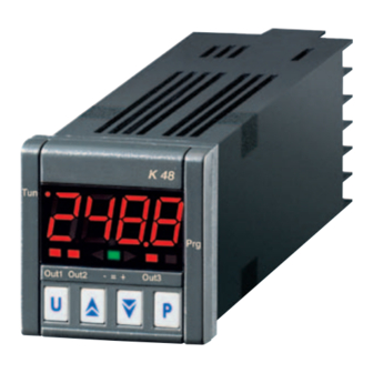
K48
CONTROLLER AND
MINI-PROGRAMMER
Engineering Manual
Code : ISTR-MK48-ENG09 - Vr. 09 (ENG)
Ascon Tecnologic S.r.l.
Viale Indipendenza 56, 27029 Vigevano (PV) - ITALY
Tel.: +39 0381 69871/FAX: +39 0381 698730
www.ascontecnologic.com
e-mail: info@ascontecnologic.com
1. OuTLINE DIMENSIONS (mm)
1.1 Dimensions
48
48
K48
Tun
283 . 5 .
Prg
Out1 Out2
Out3
45
Panel + Gasket max. 9 mm
Ascon Tecnologic - K48 Line - ENGINEERING MANUAL -Vr. 09 - PAG. 1
98
9.5
Bracket type 1
Bracket type 2
1.2 Mounting requirements
This instrument is intended for permanent installation, for
indoor use only, in an electrical panel which encloses the
rear housing, exposed terminals and wiring on the back.
Select a mounting location having the following characteristics:
1. It should be easily accessible;
2. There are minimum vibrations and no impact;
3. There are no corrosive gases;
4. There are no water or other fluids (i.e. condensation);
5. The ambient temperature is in accordance with the
operative temperature (0... 50°C);
6. The relative humidity is in accordance with the instrument
specifications (20... 85%);
The instrument can be mounted on panel with a maximum
thickness of 15 mm.
When the maximum front protection (IP65) is desired, the
optional gasket must be monted.
2. CONNECTION DIAGRAM
DI1
DI2
INPUT
TC/mV
Pt100
PTC-NTC
Out 12 VDC max. 20 mA
4... 20 mA passive (2 wires)
4... 20 mA active
Ext.
gen.
0/4...20 mA active
0... 50/60 mV; 0... 1 V; 0/1... 5 V; 0/2... 10 V
2.1 General notes about wiring
1. Do not run input wires together with power cables.
2. External components (like zener barriers, etc.) connected
between sensor and input terminals may cause errors in
measurement due to excessive and/or not balanced line
resistance or possible leakage currents.
3. When a shielded cable is used, the shield should be
connected to ground at one point only.
4. Pay attention to the line resistance; a high line resistance
may cause measurement errors.
Out1, Out2: Relay 8A-AC1 (3A-AC3)/250VAC
Out3: Relay 5A-AC1 (2A-AC3)/250VAC
SSR: 8mA/8VDC
OUT3
OUT2
Power
supply
OUT1
Advertisement
Table of Contents

Related Manuals for Ascon tecnologic K48


Summary of Contents for Ascon tecnologic K48
- Page 1 4. Pay attention to the line resistance; a high line resistance may cause measurement errors. Panel + Gasket max. 9 mm Bracket type 1 Bracket type 2 Ascon Tecnologic - K48 Line - ENGINEERING MANUAL -Vr. 09 - PAG. 1...
- Page 2 Input circuit: Current injection (25 µA). Line resistance: Not compensated. 2.2.5 V and mV Input Input impedance: > 1 MΩ Accuracy: ±0.5% of Span or ±1 dgt @ 25°C. Ascon Tecnologic - K48 Line - ENGINEERING MANUAL -Vr. 09 - PAG. 2...
- Page 3 • 10 V ±20% @ 20 mA. Note: This output is not isolated. A double or reinforced isolation between instrument output and power supply must be assured by the external solid state relay. Ascon Tecnologic - K48 Line - ENGINEERING MANUAL -Vr. 09 - PAG. 3...
- Page 4 Temperature drift: It is part of the global accuracy; Operating temperature: 0... 50°C (32... 122°F); Storage temperature: -30... +70°C (-22... +158°F); humidity: 20... 85% RH, not condensing; Protections: WATCH DOG (hardware/software) for the automatic restart. Ascon Tecnologic - K48 Line - ENGINEERING MANUAL -Vr. 09 - PAG. 4...
- Page 5 – The control output is equal to 0% and can be manually 5.4 Exiting the configuration mode modified by buttons. Push the button for more than 5 seconds, the instrument will return to the “Standard display”. Ascon Tecnologic - K Series - ENGINEERING MANUAL - Vr. 9.0 PAG. 5...
- Page 6 1 will be skipped). Note: Any modification to the parameter setting will produce a change to the parameters related with it (e.g.: set points, proportional band, etc.). Ascon Tecnologic - K Series - ENGINEERING MANUAL - Vr. 9.0 PAG. 6...
- Page 7 A short closure allows to start/stop the equal to 20 seconds. timer count while a prolonged closure (gre- ater than 10 seconds) resets the timer; Ascon Tecnologic - K Series - ENGINEERING MANUAL - Vr. 9.0 PAG. 7...
- Page 8 “fail-safe” and it is generally used in dangerous process in order to generate an alarm when the instrument power supply goes OFF or the internal watchdog starts. Ascon Tecnologic - K Series - ENGINEERING MANUAL - Vr. 9.0 PAG. 8...
- Page 9 The output repeates the digital input 2 status; St.By = Stand By status indicator; on = Out 3 forced to ON. For other details see [12] O1F parameter. Ascon Tecnologic - K Series - ENGINEERING MANUAL - Vr. 9.0 PAG. 9...
- Page 10 - [24] AL1t = LidE, Deviation high alarm (relative). Range: From [26] AL1L to [27] AL1H engineering units. time Ab1 = +0 Ab1 = +1 PWR ON Ascon Tecnologic - K Series - ENGINEERING MANUAL - Vr. 9.0 PAG. 10...
- Page 11 Range: • When one or more outputs are programmed as nonE = Alarm not used; control output: LoAb = Absolute low alarm; nonE = Alarm not used; HiAb = Absolute high alarm; Ascon Tecnologic - K Series - ENGINEERING MANUAL - Vr. 9.0 PAG. 11...
- Page 12 [46] AL3d time but the both = Enabled in both condition (when the PID re- reset is immediate. quires the maximum or the minimum power). Ascon Tecnologic - K Series - ENGINEERING MANUAL - Vr. 9.0 PAG. 12...
- Page 13 [58] Pb - Proportional band Available: When [52] cont = PID and [55] SELF = no. Range: 1... 9999 engineering units. Note: Auto-tune functions calculate this value. Ascon Tecnologic - K Series - ENGINEERING MANUAL - Vr. 9.0 PAG. 13...
- Page 14 Available: When [52] cont = PID and [55] SELF = no. Note: Auto-tune functions calculate this value but, when Range: -100.0... 100.0%. necessary, it is possible to set it manually. Ascon Tecnologic - K Series - ENGINEERING MANUAL - Vr. 9.0 PAG. 14...
- Page 15 Range: From SP1 to [72] nSP. Notes: 1. A [75] SPAt change produces the following actions: • When [80] SP.rt = SP, the remote set point will Ascon Tecnologic - K Series - ENGINEERING MANUAL - Vr. 9.0 PAG. 15...
- Page 16 • Sixth zone SP = 210 + 50 = 260°C. Reset Changing the SP of the master unit, all the other slave units will immediately change their operative set point. Ascon Tecnologic - K Series - ENGINEERING MANUAL - Vr. 9.0 PAG. 16...
- Page 17 An event can drive an output and make an 2. Setting [91] Pr.E = SPAt the instrument goes action during one or more specific program steps. Ascon Tecnologic - K Series - ENGINEERING MANUAL - Vr. 9.0 PAG. 17...
- Page 18 [98] Pr.S2 is different from [103] Pr.S3 is different from 01. 0 0 Range: 0.1... 999.9 engineering units per minute; 11. 0 0 inF = Step transfer. Ascon Tecnologic - K Series - ENGINEERING MANUAL - Vr. 9.0 PAG. 18...
- Page 19 6. When “Program run/hold/reset” is selected, a short Note: For more details see [97] Pr.E1 parameter. press starts/stops (Hold) program execution while a long press (longer than 10 s) resets the program. Ascon Tecnologic - K Series - ENGINEERING MANUAL - Vr. 9.0 PAG. 19...
- Page 20 Note: This is a “window filter” related to the set point; it is ap- plied to the displayed value only and has no effect on the other instrument functions (control, alarms, etc.). Ascon Tecnologic - K Series - ENGINEERING MANUAL - Vr. 9.0 PAG. 20...
- Page 21 Range: oFF = Threshold not used; – Press button for more than 10 seconds; 1... 999 days; 1... 999 hours. – The instrument returns to the “Standard display”. Ascon Tecnologic - K Series - ENGINEERING MANUAL - Vr. 9.0 PAG. 21...
- Page 22 - SPAt - SPAt - AL1 - - AL1 - - AL2 - ....- Pb - - Int - - dEr - - Aut.r - A 10 Aut.r Ascon Tecnologic - K Series - ENGINEERING MANUAL - Vr. 9.0 PAG. 22...
- Page 23 1000 plus the programmed password (e.g. 1000 + 20 [default] = 1020). It is always possible to manually End the param- eter configuration procedure (see below). Ascon Tecnologic - K Series - ENGINEERING MANUAL - Vr. 9.0 PAG. 23...
- Page 24 If no buttons are pressed for more than 10 When the program is running the door is locked. seconds the instrument automatically returns to the “Standard display”. Ascon Tecnologic - K Series - ENGINEERING MANUAL - Vr. 9.0 PAG. 24...
- Page 25 4. During manual mode, all functions not related If the error does not disappear, send the instru- with the control (wattmeter, indipendent timer, ment to your supplier. “worked time”, etc) continue to operate normally. Ascon Tecnologic - K Series - ENGINEERING MANUAL - Vr. 9.0 PAG. 25...
- Page 26 5. Make sure that there are no loose terminals. 6. Before putting the instrument back in its case, make sure that it is perfectly dry. 7. Put the instrument back and turn it ON. Ascon Tecnologic - K Series - ENGINEERING MANUAL - Vr. 9.0 PAG. 26...
- Page 27 Sequential set point selection 17 = SP1 / SP2 selection 18 = Set point Binary selection 19 = Digital inputs in parallel to keys 20 = timer Run/Reset Ascon Tecnologic - K Series - ENGINEERING MANUAL -Vr. 9.0 PAG. 27...
- Page 28 Sensor break (burn out) dir = Direct action rEU = Reverse action o2Ac Out 2 action dir.r = Direct with reversed LED ReU.r = Reverse with reversed LED Ascon Tecnologic - K Series - ENGINEERING MANUAL -Vr. 9.0 PAG. 28...
- Page 29 Sensor break (burn out) dir = Direct action rEU = Reverse action o4Ac Out 3 action dir.r = Direct with reversed LED ReU.r = Reverse with reversed LED Ascon Tecnologic - K Series - ENGINEERING MANUAL -Vr. 9.0 PAG. 29...
- Page 30 Alarm 2 delay From 0 (oFF) to 9999 (s) Never Alarm 2 enabling during Stand-by During stand by AL2o mode During overrange and underrange During overrange, underrange and stand-by Ascon Tecnologic - K Series - ENGINEERING MANUAL -Vr. 9.0 PAG. 30...
- Page 31 ON and after a set point change oFF = Not active Aut.r Manual start of the Autotuning A-26 on = Active YES = Active SELF Self tuning enabling no = Not active Ascon Tecnologic - K Series - ENGINEERING MANUAL -Vr. 9.0 PAG. 31...
- Page 32 Rate of rise for POSITIVE set point change 0.01... 100.00 (inF) Engineering units per minute SP.d Rate of rise for NEGATIVE set point change 2 0.01... 100.00 (inF) Engineering units per minute Ascon Tecnologic - K Series - ENGINEERING MANUAL -Vr. 9.0 PAG. 32...
- Page 33 From 0 (oFF) to 9999 (E.U.) A-91 Pr.E4 Events of the fourth group 00.00... 11.11 00.00 rES = Program reset Pr.St Program status run = Program start HoLd = Program hold Ascon Tecnologic - K Series - ENGINEERING MANUAL -Vr. 9.0 PAG. 33...
- Page 34 19.2 38.4 nonE = Not used Selection of the value to be retransmit- trSP rSP = Operative set point nonE ted (Master) PErc = Current power output (%) Ascon Tecnologic - K Series - ENGINEERING MANUAL -Vr. 9.0 PAG. 34...
- Page 35 A.L.o Adjust low Offset -300... 300 (E.U.) A-10 A.H.P Adjust High Point From A.L.P +10 to 9999 (E.U.) 9999 A-11 A.H.o Adjust High Offset -300... 300 (E.U.) A-12 Ascon Tecnologic - K Series - ENGINEERING MANUAL -Vr. 9.0 PAG. 35...
- Page 36 Ascon Tecnologic - K Series - ENGINEERING MANUAL -Vr. 9.0 PAG. 36...
Need help?
Do you have a question about the K48 and is the answer not in the manual?
Questions and answers