Table of Contents
Advertisement
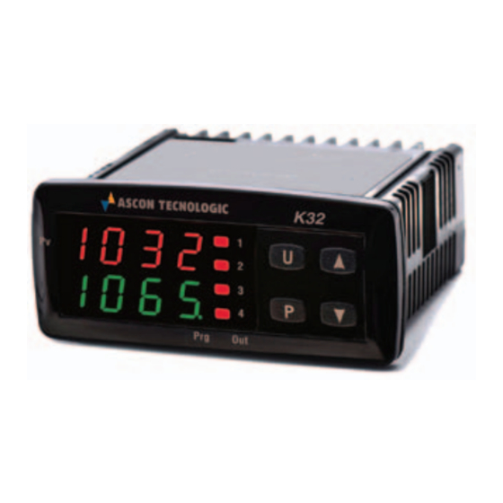
K32
CONTROLLER AND
MINI-PROGRAMMER
Engineering Manual
20/10 - Code: ISTR_M_K32-_E_10_--
Ascon Tecnologic S.r.l.
Viale Indipendenza 56, 27029 Vigevano (PV) - ITALY
Tel.: +39 0381 69871/FAX: +39 0381 698730
www.ascontecnologic.com
e-mail: info@ascontecnologic.com
1. OuTLINE DIMENSIONS (mm)
1.1 Dimensions
78
K32
1032
1
U
PV
2
1098.
3
P
4
Prg
Out
Brackets
1.2 Mounting requirements
This instrument is intended for permanent installation, for
indoor use only, in an electrical panel which encloses the
rear housing, exposed terminals and wiring on the back.
Select a mounting location having the following characteristics:
1. It should be easily accessible;
2. There are minimum vibrations and no impact;
3. There are no corrosive gases;
4. There are no water or other fluids (i.e. condensation);
5. The ambient temperature is in accordance with the
operative temperature (0... 50°C);
6. The relative humidity is in accordance with the instrument
specifications (20... 85%);
When the maximum front protection (IP65) is desired, the
optional screw type bracket must be mounted (see the
"How to Order" paragraph).
5.5
64
71
34 34
Ascon Tecnologic - K32 Line - ENGINEERING MANUAL - PAG. 1
2. CONNECTION DIAGRAM
0... 50/60 mV; 0... 1 V; 0/1... 5 V; 0/2... 10 V
0/4... 20 mA active
4... 20 mA active
Ext.
gen.
4... 20 mA passive (2 wires)
PTC-NTC
DI1
Pt100
TC/mV
RELAYS: Out-1, 2: 8A-AC1 (3A-AC3)/250VAC
RELAYS: Out-3, 4: 5A-AC1 (2A-AC3)/250VAC
Power
OUT4
supply
2.1 General notes about wiring
1. Do not run input wires together with power cables.
2. External components (like zener barriers, etc.) connected
between sensor and input terminals may cause errors in
measurement due to excessive and/or not balanced line
resistance or possible leakage currents.
3. When a shielded cable is used, the shield should be
connected to ground at one point only.
4. Pay attention to the line resistance; a high line resistance
may cause measurement errors.
2.2 Inputs
2.2.1 Termocouple Input
+
1
-
2
External resistance: 100Ω max., maximum error 0.5% of span.
Cold junction: Automatic compensation between 0... 50°C.
Cold junction accuracy: 0.1°C/°C after a warm-up of
20 minutes.
Input impedance: > 1 MΩ.
Calibration: According to EN 60584-1.
Note: For TC wiring use proper compensating cable
preferable shielded.
2.2.2 Infrared Sensor Input
+
1
-
2
External resistance: Not relevant.
Cold junction: Automatic compensation between 0... 50°C.
Cold junction accuracy: 0.1°C/°C.
Input impedance: > 1 MΩ.
DI2
RS485
B
GND A
SSR: 10mA/10VDC
OUT3
OUT2
OUT1
Exergen
Advertisement
Table of Contents

Related Manuals for Ascon tecnologic K32


Summary of Contents for Ascon tecnologic K32
- Page 1 Cold junction accuracy: 0.1°C/°C. When the maximum front protection (IP65) is desired, the Input impedance: > 1 MΩ. optional screw type bracket must be mounted (see the “How to Order” paragraph). Ascon Tecnologic - K32 Line - ENGINEERING MANUAL - PAG. 1...
-
Page 2: Logic Inputs
Note: This output is not isolated. A double or reinforced isolation between instrument output and power supply 0/4... 20 mA input wiring for active transmitter must be assured by the external solid state relay. 0/4...20 mA Active transmitter Ascon Tecnologic - K32 Line - ENGINEERING MANUAL - PAG. 2... -
Page 3: Serial Interface
1 (MARK or OFF) state. • The “A” terminal of the generator shall be positive with respect to the “B” terminal for a binary 0 (SPACE or ON). Ascon Tecnologic - K32 Line - ENGINEERING MANUAL - PAG. 3... -
Page 4: Power Supply
Temperature drift: It is part of the global accuracy; Operating temperature: 0... 50°C (32... 122°F); Storage temperature: -30... +70°C (-22... +158°F); humidity: 20... 85% RH, not condensing; Protections: WATCH DOG (hardware/software) for the automatic restart. Ascon Tecnologic - K32 Line - ENGINEERING MANUAL - PAG. 4... -
Page 5: Configuration Procedure
– The control output is equal to 0% and can be manually modified by buttons. Push the button for more than 5 seconds, the instrument will return to the “Standard display”. Ascon Tecnologic - K Series - ENGINEERING MANUAL - PAG. 5... - Page 6 [Alarm 1 type] equal to nonE [not used], all parameters (e.g.: set points, proportional band, etc.). related with the alarm 1 will be skipped). Ascon Tecnologic - K Series - ENGINEERING MANUAL - PAG. 6...
- Page 7 A short closure allows to start/stop the timer equal to 20 seconds. count while a prolonged closure (greater than 10 seconds) resets the timer; Ascon Tecnologic - K Series - ENGINEERING MANUAL - PAG. 7...
- Page 8 “fail-safe” and it is generally used in dangerous process in order to generate an alarm when the instrument power supply goes OFF or the internal watchdog starts. Ascon Tecnologic - K Series - ENGINEERING MANUAL - PAG. 8...
- Page 9 The output repeates the digital input 1 status; diF2 The output repeates the digital input 2 status; St.By Stand By status indicator; Out 3 forced to ON. For other details see [12] O1F parameter. Ascon Tecnologic - K Series - ENGINEERING MANUAL - PAG. 9...
- Page 10 - [24] AL1t = LodE, Deviation low alarm (relative); - [24] AL1t = LidE, Deviation high alarm (relative). Range: From [26] AL1L to [27] AL1H engineering units. time Ab1 = +0 Ab1 = +1 PWR ON Ascon Tecnologic - K Series - ENGINEERING MANUAL - PAG. 10...
- Page 11 • When no output is programmed as control output: Range: • When one or more outputs are programmed as nonE Alarm not used; control output: LoAb Absolute low alarm; nonE Alarm not used; HiAb Absolute high alarm; Ascon Tecnologic - K Series - ENGINEERING MANUAL - PAG. 11...
- Page 12 [46] AL3d time but the both Enabled in both condition (when the PID re- reset is immediate. quires the maximum or the minimum power). Ascon Tecnologic - K Series - ENGINEERING MANUAL - PAG. 12...
- Page 13 1... 9999 seconds. [58] Pb - Proportional band Available: When [52] cont = PID and [55] SELF = no. Range: 1... 9999 engineering units. Note: Auto-tune functions calculate this value. Ascon Tecnologic - K Series - ENGINEERING MANUAL - PAG. 13...
- Page 14 Available: When [52] cont = PID and [55] SELF = no. • When [62] H.Act = SLou: 40.0... 130.0 seconds. Range: -100.0... 100.0%. Note: Auto-tune functions calculate this value but, when necessary, it is possible to set it manually. Ascon Tecnologic - K Series - ENGINEERING MANUAL - PAG. 14...
- Page 15 SS.tH parameter. Range: From SP1 to [72] nSP. Notes: 1. A [75] SPAt change produces the following actions: • When [80] SP.rt = SP, the remote set point will Ascon Tecnologic - K Series - ENGINEERING MANUAL - PAG. 15...
- Page 16 • Sixth zone SP = 210 + 50 = 260°C. Reset Changing the SP of the master unit, all the other slave units will immediately change their operative set point. Ascon Tecnologic - K Series - ENGINEERING MANUAL - PAG. 16...
- Page 17 An event can drive an output and make an 2. Setting [91] Pr.E = SPAt the instrument goes action during one or more specific program steps. Ascon Tecnologic - K Series - ENGINEERING MANUAL - PAG. 17...
- Page 18 10. 0 0 [98] Pr.S2 is different from [103] Pr.S3 is different from 01. 0 0 Range: 0.1... 999.9 engineering units per minute; 11. 0 0 Step transfer. Ascon Tecnologic - K Series - ENGINEERING MANUAL - PAG. 18...
- Page 19 6. When “Program run/hold/reset” is selected, a short Note: For more details see [97] Pr.E1 parameter. press starts/stops (Hold) program execution while a long press (longer than 10 s) resets the program. Ascon Tecnologic - K Series - ENGINEERING MANUAL - PAG. 19...
- Page 20 Starts in manual mode with a power output equal to zero; Note: For more details see [80] SP.rt (Remote set point type) St.bY Starts in stand-by mode. parameter. Ascon Tecnologic - K Series - ENGINEERING MANUAL - PAG. 20...
- Page 21 In order to exit from configuration parameter procedure, proceed as follows: – Press button; – Press button for more than 10 seconds; – The instrument returns to the “Standard display”. Ascon Tecnologic - K Series - ENGINEERING MANUAL - PAG. 21...
- Page 22 - AL1 - - SPAt - SPAt - AL2 - - AL1 - - Pb - ....- Int - - dEr - - Aut.r - A 10 Aut.r Ascon Tecnologic - K Series - ENGINEERING MANUAL - PAG. 22...
-
Page 23: Operative Modes
Displays the “Additional information” (see below). When you desire to remove the time out (e.g. for the first configuration of an instrument) you can use a password equal to 1000 plus the programmed Ascon Tecnologic - K Series - ENGINEERING MANUAL - PAG. 23... -
Page 24: Additional Information
If no buttons are pressed for more than 10 soak 1, ramp 2 and soak 2). seconds the instrument automatically returns to the When the program is running the door is locked. Standard display. Ascon Tecnologic - K Series - ENGINEERING MANUAL - PAG. 24... -
Page 25: Manual Mode
4. During manual mode, all functions not related with the control (wattmeter, indipendent timer, “worked time”, etc.) continue to operate normally. Ascon Tecnologic - K Series - ENGINEERING MANUAL - PAG. 25... -
Page 26: General Notes
Ascon Tecnologic, except in the event of in any case not in compliance with the instrument’s features. - Page 27 Out-of-range, burn out and Power failure indicator diF.1 The output repeats the digital input 1 status diF.2 The output repeats the digital input 2 status St.bY Stand by status indicator Out 1 forced to ON Ascon Tecnologic - K Series - ENGINEERING MANUAL - PAG. 27...
- Page 28 Alarm 3 Loop break alarm + 16 Sensor break (burn out) Direct action Reverse action 20 o3Ac Out 3 action dir.r Direct with reversed LED ReU.r Reverse with reversed LED Ascon Tecnologic - K Series - ENGINEERING MANUAL - PAG. 28...
- Page 29 Alarm 3 Loop break alarm + 16 Sensor break (burn out) Direct action Reverse action 23 o4Ac Out 3 action dir.r Direct with reversed LED ReU.r Reverse with reversed LED Ascon Tecnologic - K Series - ENGINEERING MANUAL - PAG. 29...
- Page 30 Alarm 2 delay From 0 (oFF) to 9999 (s) Never During stand by 39 AL2o Alarm 2 enabling during Stand-by mode During overrange and underrange During overrange, underrange and stand-by Ascon Tecnologic - K Series - ENGINEERING MANUAL - PAG. 30...
- Page 31 Self tuning enabling Not active 56 HSEt Hysteresis of the ON/OFF control 0... 9999 ( E.U.) A-27 57 cPdt Time for compressor protection From 0 (oFF) to 9999 (s) Ascon Tecnologic - K Series - ENGINEERING MANUAL - PAG. 31...
- Page 32 When tr.u < 2: From 00.00 (oFF) to 99.59 (inF) 87 tr.t2 Time 2 1.00 A-65 When tr.u = 2: From 000.0 (oFF) to 995.9 (inF) Timer reset 88 tr.St Timer status Timer run HoLd Timer hold Ascon Tecnologic - K Series - ENGINEERING MANUAL - PAG. 32...
- Page 33 Wait band of the fourth soak A-91 1... 9999 (E.U.) 112 Pr.E4 Events of the fourth group 00.00... 11.11 00.00 Program reset 113 Pr.St Program status Program start HoLd Program hold Ascon Tecnologic - K Series - ENGINEERING MANUAL - PAG. 33...
- Page 34 Baud rate 9600 9600 19.2 38.4 nonE Not used Selection of the value to be retransmit- 125 trSP Operative set point nonE ted (Master) PErc Current power output (%) Ascon Tecnologic - K Series - ENGINEERING MANUAL - PAG. 34...
- Page 35 Adjust low Offset -300... 300 (E.U.) A-10 132 AH.P Adjust High Point From AL.P +10 to 9999 (E.U.) 9999 A-11 133 AH.o Adjust High Offset -300... 300 (E.U.) A-12 Ascon Tecnologic - K Series - ENGINEERING MANUAL - PAG. 35...
- Page 36 Ascon Tecnologic - K Series - ENGINEERING MANUAL - PAG. 36...
Need help?
Do you have a question about the K32 and is the answer not in the manual?
Questions and answers