Falcon 1092 Continental User's Manual & Installation Instructions
Hide thumbs
Also See for 1092 Continental:
- User manual (60 pages) ,
- User's manual & installation instructions (40 pages) ,
- User's manual & installation and servicing instructions (36 pages)
Table of Contents
Advertisement
Quick Links
Advertisement
Table of Contents

Related Manuals for Falcon 1092 Continental


Summary of Contents for Falcon 1092 Continental
- Page 1 USER GUIDE & INSTALLATION INSTRUCTIONS 1092 Continental Induction U110968 - 02a...
-
Page 3: Table Of Contents
Contents Before you start... Troubleshooting Personal safety Installation Electrical connection safety Dear Installer Peculiar smells Safety Requirements and Regulations Ventilation Provision of Ventilation Maintenance Location of Cooker Induction care Positioning the Cooker Oven care Moving the Cooker Hob care Lowering the Two Rear Rollers Cooling fan Completing the Move Cooker care... -
Page 4: Before You Start
Before you start... Your cooker should give you many years of cooking process has to be supervised trouble-free cooking if installed and operated continuously. correctly. It is important that you read this DANGER OF FIRE: DO NOT store items on •... -
Page 5: Peculiar Smells
for the Electrical Load of the appliance and Ventilation comply with the relevant national and local The use of a cooking appliance results in the requirements. production of heat and moisture in the room in which it is installed. Make sure that the kitchen The cooker may be installed in a kitchen/ •... - Page 6 burst and cause injury. Fig. 1.1 DO NOT use unstable saucepans. ALWAYS • make sure that you position the handles away from the edge of the hotplate. NEVER leave the hotplate unattended • at high heat settings. Pans boiling over can cause smoking, and greasy spills may catch on fire.
-
Page 7: Induction Care
DO NOT modify this appliance. This • Fig. 1.5 appliance is not intended to be operated by means of external timer or separated ArtNo.312-0001 Not cooking surface remote-control system. If flammable materials are stored in the • drawer, oven(s) or grill(s) it may explode and result in fire or property damage. -
Page 8: Oven Care
Only certain types of glass, glass-ceramic, DO NOT place anything between the • • earthenware or other glazed containers base of the pan and the hob surface (e.g. are suitable for use on the warming zone; asbestos mats, aluminium foil, wok stand). others may break because of the sudden Take care NOT to place metallic objects •... -
Page 9: Hob Care
Accidental damage may cause the door position before removing a pan. • glass panel to fracture. Avoid heating an empty pan. Doing so may • Keep oven vent ducts unobstructed. damage both the hob and pan. • DO NOT use harsh abrasive cleaners or •... - Page 10 Take care that no water seeps into the • appliance. Before you remove any of the grill parts for • cleaning, make sure that they are cool or use oven gloves. DO NOT use any abrasive substances on • the grill and grill parts. DO NO put the side runners in a •...
-
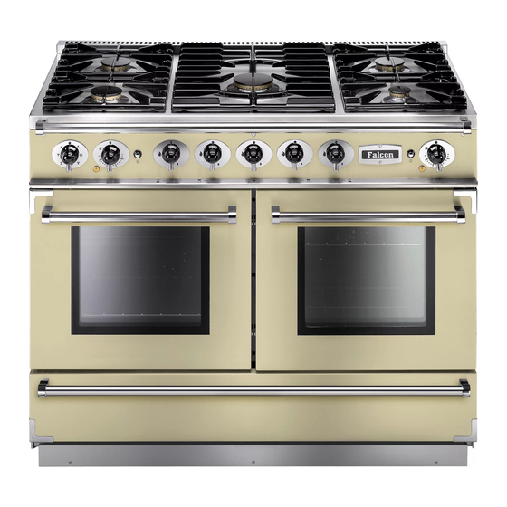
Page 11: Cooker Overview
2. Cooker Overview Fig.2.1 The 110 induction cooker (Fig.2.1) has the following features: Fig.2.2 5 induction cooking zones Control panel Multi-function oven Fan oven Storage drawer The Hob Use only pans that are suitable for induction hobs. We recommend stainless steel, enamelled steel pans or cast iron pans with enamelled bases. - Page 12 The very best pans have bases that are very slightly curved Fig.2.3 up when cold (Fig.2.3). If you hold a ruler across the bottom you will see a small gap in the middle. When they heat up the metal expands and lies flat on the cooking surface. Make sure that the base of the pan is clean and dry to prevent any residue burning onto the hob panel.
- Page 13 Residual Heat Indicator, H Automatic heat-up time at Power level 100% (min:sec) After use, a cooking zone will remain hot for a while as heat dissipates. When a cooking zone is switched off the residual 0:48 heat indicator symbol [H ], will appear in the display. This 2:24 shows that the cooking zone temperature is above 60 °C and may still cause burns.
- Page 14 Low Temperature Setting, L1/L2 Maximum Operating Time Power Level This function should only be used when heating from cold. 2 hours L1 and L2 Each cooking area is equipped with 2 low temperature 6 hours settings: 6 hours L1 will maintain a temperature of about 40 °C – ideal for •...
-
Page 15: The Ovens
The Ovens Fig.2.9 References to ‘left-hand’ and ‘right-hand’ ovens apply as viewed from the front of the appliance. The left-hand oven is a multi-function oven. The right-hand oven is a fan oven. Multi-function Ovens Multi-function ovens have an oven fan and oven fan element, as well as two extra heating elements (Fig.2.9). - Page 16 Conventional Oven (Top and Base Heat) Multi-function Oven Functions This function combines the heat from the top and Fan Oven base elements. It is particularly suitable for roasting This function operates the fan and the heating and baking pastry, cakes and biscuits. element around it.
- Page 17 Turn the oven knob to the desired temperature (Fig.2.11). The oven indicator light will glow until the oven has reached the temperature you selected (Fig.2.12). It will then cycle on ArtNo.192-0107 - Falcon oven temp control and off during cooking as the oven maintains the selected temperature.
-
Page 18: Accessories
Accessories Fig.2.13 Oven shelves Shelf guard The oven shelves are retained when pulled forward but can be easily removed and refitted (Fig.2.13). The oven shelves can be easily removed and refitted. Pull the shelf forward until the back of the shelf is stopped by the shelf stop bumps in the oven sides (Fig.2.14). -
Page 19: Cooking Tips
Cooking Tips Hints on Using Your Induction Cooker General Oven Tips If you have not used an induction cooker before please be The wire shelves should always be pushed firmly to the back aware of the following: of the oven. •... -
Page 20: Cooking Table
Cooking Table The oven control settings and cooking times given in the table below are intended to be used as a Top (T) guide only. Individual tastes may require the temperature to be altered to provide a preferred result. ArtNo.050-0007 Centre (C) Oven shelf positions Food is cooked at lower temperature in a fan oven than in a conventional oven. -
Page 21: Cleaning Your Cooker
Cleaning your cooker Isolate the electricity supply before carrying out any Fig. 5.1 major cleaning. Then allow the cooker to cool. NEVER use paint solvents, washing soda, caustic cleaners, biological powders, bleach, chlorine based bleach cleaners, coarse abrasives or salt. DO NOT mix different cleaning products –... -
Page 22: To Remove Metal Rub-Off
To Remove Metal Rub-off Fig. 5.2 Sliding pans on the hob - especially aluminium or copper pans - can leave marks on the surface. These marks often appear like scratches, but can easily be removed using the procedure described previously for ‘Cleaning spills’... -
Page 23: Cleaning Table
Cleaning table Cleaners listed (Table 5.1) are available from supermarkets or electrical retailers as stated. For enamelled surfaces use a cleaner that is approved for use on vitreous enamel. Regular cleaning is recommended. For easier cleaning, wipe up any spillages immediately. Hotplate Part Finish... -
Page 24: Troubleshooting
Troubleshooting DocNo.050-0001 - Troubleshooting - Induction GENERIC Interference with and repairs to the hob MUST NOT My hob is scratched be carried out by unqualified persons. Do not try Always use the cleaning methods recommended in this to repair the hob as this may result in injury and guide, and make sure that the pan bottoms are smooth and damage to the hob. - Page 25 The oven light is not working Fig. 6.1 The bulb has probably blown. You can buy a replacement bulb (which is not covered under the guarantee) from most electrical stores. Ask for a 40 W - 230 V halogen lamp (G9) (Fig.
-
Page 26: Installation
INSTALLATION Check the appliance is electrically safe when you have finished. 7. Installation Dear Installer Location of Cooker Before you start your installation, please complete the details The cooker may be installed in a kitchen/kitchen diner but below, so that, if your customer has a problem relating to NOT in a room containing a bath or shower. -
Page 27: Positioning The Cooker
INSTALLATION Check the appliance is electrically safe when you have finished. Positioning the Cooker Fig.7.1 Fig.7.1 and Fig.7.2 show the minimum recommended distance from the cooker to nearby surfaces. 75 mm 75 mm 800 mm The cooker should not be placed on a base. minimum The hotplate surround should be level with, or above, any adjacent work surface. -
Page 28: Lowering The Two Rear Rollers
INSTALLATION Check the appliance is electrically safe when you have finished. Lowering the Two Rear Rollers Fig.7.5 To adjust the height of the rear of the cooker, first fit a 13 mm spanner or socket wrench onto the hexagonal adjusting nut (Fig.7.5). -
Page 29: Electrical Connection
INSTALLATION Check the appliance is electrically safe when you have finished. Electrical Connection Fig.7.11 This appliance must be installed by a suitably qualified electrician to comply with the relevant electrical regulations, and also the local electricity supply company requirements. Current Operated Earth Leakage Breakers The combined use of your cooker and other domestic appliances may cause nuisance tripping, so we 10 mm²... -
Page 30: Final Fitting
INSTALLATION Check the appliance is electrically safe when you have finished. Final Fitting Fig.7.13 Fitting the Plinth Remove the 3 screws for the plinth mounts along the front bottom edge of the cooker (Fig.7.13). Fasten the plinth using these screws. Final Checks Hob Check Check each cooking zone in turn. - Page 31 INSTALLATION Check the appliance is electrically safe when you have finished.
-
Page 32: Fitting The Drawer
INSTALLATION Check the appliance is electrically safe and gas sound when you have finished. Fitting the drawer Removing the drawer... -
Page 33: Circuit Diagram
8. Circuit Diagram Induction Hob Right Rear Left Front Left Rear Centre Right Front Interface board Hob Display Induction unit 6 way connector 6 way connector Code Colour Brown Blue Green... -
Page 34: Oven
Oven P095199 P038434 Legend The connections shown in the circuit diagram are for single-phase. The ratings are for 230 V 50 Hz. Component positions viewed from the front of the cooker. Code Description Code Description Code Colour Blue Left Hand Oven Thermostat Neon Brown Left Hand Oven Multifunction Switch... -
Page 35: Technical Data
Technical Data INSTALLER: Please leave these instructions with the user. DATA BADGE LOCATION: Cooker back, serial number repeater badge below the oven door opening. COUNTRY OF DESTINATION: GB, IE, FR, NL, DE, SE, BE. Connection Electric 230 / 400 V ~ 50 Hz 3N Dimensions Total height Min 915 mm... - Page 36 660 DEPTH INCLUDING HANDLES 1092 600 DEPTH INCLUDING HANDLES...
- Page 37 Hotplate Efficiency Data Brand Falcon Model Identification Continental Size 1092 Type Induction Type of Hob Induction Number of electric zones Zone 1 - Ø cm 15.5 Heating Technology Energy Consumption (ECElectric cooking) - Wh/kg Zone 2 - Ø cm 18.5...
- Page 38 Oven data Brand Falcon Model identification 1092 Continental Type of oven Electric Mass Number of cavities Left-hand Efficiency Fuel type Electric Cavity type Multifunction Power - conventional Power - forced air convection Volume Litres Energy consumption (electricity) - conventional kWh / cycle 1.01...
- Page 39 NOTES...
- Page 40 Clarence Street, Royal Leamington Spa, Warwickshire, CV31 2AD, England. www.falconworld.com...
Need help?
Do you have a question about the 1092 Continental and is the answer not in the manual?
Questions and answers