Table of Contents
Advertisement
Advertisement
Table of Contents

Related Manuals for Falcon 1000 Deluxe Induction G5


Summary of Contents for Falcon 1000 Deluxe Induction G5
- Page 1 USER GUIDE & INSTALLATION INSTRUCTIONS 1000 Deluxe Induction G5...
- Page 2 SLOW BAKED LEG OF LAMB METHOD 1. Preheat the oven to 220 ¡C (for a conventional oven), 200 ¡C (for a fan oven) or gas mark 7. 2. Pull the small sprigs off the rosemary branches and set aside with the garlic. 2.
-
Page 3: Table Of Contents
Cooking with a Multi-function Oven Circuit Diagrams General Oven Tips Circuit Diagram: Hob Cooking Table Circuit Diagram: Oven Cleaning Your Cooker Technical Data Glide-out Grill Control Panel and Oven Doors Ovens The Tall Oven Cleaning Table Falcon 1000 Deluxe Induction G5 U110192-02... -
Page 5: Before You Start
1. Before You Start... Personal Safety Thank you for buying this cooker. It should give you many years of trouble-free cooking if installed and operated Important information for pacemaker and implanted correctly. insulin pump users: The functions of this hob comply with Your cooker should give you many years of trouble-free the applicable European standards on electromagnetic cooking if installed and operated correctly. - Page 6 Always keep combustible materials, e.g. curtains, and Fig.1-1 ammable liquids a safe distance away from your cooker. DO NOT spray aerosols in the vicinity of the cooker while it is on. Cooking high moisture content foods can create a ‘steam burst’...
-
Page 7: Hob Care
Hob Care Fig.1-3 NEVER cook directly on the hob surface (Fig.1-2). DO NOT use the hob surface as a cutting board. DO NOT leave utensils, foodstu s or combustible items on the hob when it is not is use (e.g. tea towels, frying pans containing oil). -
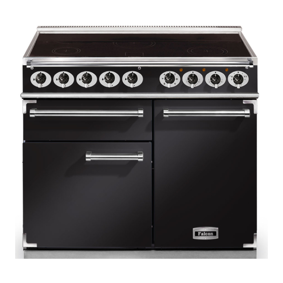
Page 8: Cooker Overview
2. Cooker Overview Fig.2-1 The 1000 induction cooker (Fig.2-1) has the following Fig.2-2 features: 5 induction cooking zones A control panel A glide-out grill Main multi-function oven Tall fan oven The Hob Use only pans that are suitable for induction hobs. We recommend stainless steel, enamelled steel pans or cast iron pans with enamelled bases. - Page 9 The very best pans have bases that are very slightly curved Fig.2-3 up when cold (Fig.2-3). If you hold a ruler across the bottom you will see a small gap in the middle. When they heat up the metal expands and lies at on the cooking surface. Make sure that the base of the pan is clean and dry to prevent any residue burning onto the hob panel.
-
Page 10: Child Lock
Residual Heat Indicator, H Automatic heat-up time at Power level 100% (min:sec) After use, a cooking zone will remain hot for a while as heat dissipates. When a cooking zone is switched o the residual 0:48 heat indicator symbol [H ], will appear in the display. This 2:24 shows that the cooking zone temperature is above 60 °C and may still cause burns. - Page 11 Low Temperature Setting, L1/L2 Fig.2-8 Each cooking area is equipped with 2 low temperature settings: A & B linked D & E linked L1 will maintain a temperature of about 40 °C – ideal for gently melting butter or chocolate. L2 will maintain a temperature of about 90 °C –...
-
Page 12: The Glide-Out Grill
The Glide-out Grill Fig.2-9 CAUTION: This applicance is for cooking purposes only. It must not be used for other purposes, for example room heating. CAUTION: Accessible parts may be hot when the grill is in use. Young children should be kept away. Open the door and pull the grill pan carriage forward using the handle (Fig.2-9). -
Page 13: The Ovens
The Ovens Function The left-hand oven is a multi-function oven, while the right- To thaw small items in the oven without Defrost hand tall oven is a fan oven. heat A full cooking function, even heat The Multi-function Oven Fan oven throughout, great for baking As well as the oven fan and fan element, they are fitted Grilling meat and fish with the door... - Page 14 Fan Assisted Oven Multi-function Oven Functions This function operates the fan, circulating air heated Defrost by the elements at the top and the base of the oven. This function operates the fan to circulate cold air The combination of fan and conventional cooking only.
-
Page 15: Operating The Ovens
Turn the oven knob to the desired temperature (Fig.2-14). The oven indicator light will glow until the oven has reached Fig.2-14 the temperature selected (Fig.2-15). It will then cycle on and o during cooking. ArtNo.192-0107 - Falcon oven temp control Fig.2-15 ArtNo.192-0104 - Falcon oven light... -
Page 16: Accessories
Accessories Fig.2-16 Flat shelf Oven Shelves – Left-hand (Main) Oven Shelf guard In addition to the at shelves, your cooker is supplied with a drop shelf (Fig.2-16). The drop shelf increases the possibilities for oven shelf spacing. Front With the exception of the top position, which will only accept the drop shelf, any shelf can t in any of the positions (Fig.2-17). -
Page 17: Cooking Tips
3. Cooking Tips Using Your Induction Cooker General Oven Tips If you have not used an induction cooker before please be The wire shelves should always be pushed firmly to the back aware of the following: of the oven. Make sure that the pans you have or buy are suitable for use Baking trays with food cooking on them should be placed on the induction hob. -
Page 18: Cooking Table
4. Cooking Table DocNo.031-0004 - Cooking table - electric & fan single cavity The oven control settings and cooking times given in the table below are intended to be used Top (T) AS A GUIDE ONLY. Individual tastes may require the temperature to be altered to provide a preferred result. -
Page 19: Cleaning Your Cooker
5. Cleaning Your Cooker Isolate the electricity supply before carrying out any major Fig.5-1 cleaning. Allow the cooker to cool. NEVER use paint solvents, washing soda, caustic cleaners, biological powders, bleach, chlorine based bleach cleaners, coarse abrasives or salt. DO NOT mix di erent cleaning products – they may react together with hazardous results. -
Page 20: Glide-Out Grill
Glide-out Grill Fig.5-2 Before you remove any of the grill parts for cleaning, make sure that they are cool, or use oven gloves. Wash the grill pan and trivet washed in hot soapy water. Alternatively, wash the grill pan in a dishwasher. After grilling meats or any foods that soil, leave to soak for a few minutes in the sink immediately after use. -
Page 21: Control Panel And Oven Doors
Control Panel and Oven Doors Fig.5-6 The control panel and control knobs should only be cleaned with a soft cloth wrung out in clean hot soapy water – but take care that no surplus water seeps into the appliance. Wipe with a clean dampened cloth then polish with a dry cloth. -
Page 22: Cleaning Table
Cleaning Table Cleaners listed (Table 5-1) are available from supermarkets or electrical retailers as stated. For enamelled surfaces use a cleaner that is approved for use on vitreous enamel. Regular cleaning is recommended. For easier cleaning, wipe up any spillages immediately. Hotplate Part Finish... -
Page 23: Troubleshooting
6. Troubleshooting DocNo.053-0003 - Troubleshooting - In G5 Interference with and repairs to the hob MUST NOT The induction hob is noisy be carried out by unquali ed persons. Do not try When using the induction hob there may be some to repair the hob as this may result in injury and ‘noise’... - Page 24 If there is an installation problem and I don’t get my The oven is not cooking evenly original installer to come back to fix it, who pays? Do not use a baking tray with dimensions larger than You do. Service organisations will charge for their call- those specified in the section on ‘General Oven Tips’...
-
Page 25: Installation
INSTALLATION Check the appliance is electrically safe when you have nished. 7. Installation You will need the following equipment to complete the Dear Installer cooker installation satisfactorily: Before you start your installation, please complete the details • Multimeter (for electrical checks). below, so that, if your customer has a problem relating to your installation, they will be able to contact you easily. -
Page 26: Positioning The Cooker
INSTALLATION Check the appliance is electrically safe when you have nished. Positioning the Cooker Fig.7-1 Fig.7-1 shows the minimum recommended distance from the cooker to nearby surfaces. 75 mm 75 mm 800 mm The cooker should not be placed on a base. Above hotplate surround should be level with, or above, any adjacent work surface. -
Page 27: Completing The Move
INSTALLATION Check the appliance is electrically safe when you have nished. Lowering the Two Rear Rollers Fig.7-5 To adjust the height of the rear of the cooker, rst t a 13 mm spanner or socket wrench onto the hexagonal adjusting nut (Fig.7-5). -
Page 28: Electrical Connection
INSTALLATION Check the appliance is electrically safe when you have nished. Electrical Connection Fig.7-7 The cooker must be installed by a quali ed electrician, in accordance with all relevant British Standards/Codes of Practice (in particular BS 7671), or with the relevant national and local regulations. -
Page 29: Circuit Diagrams
8. Circuit Diagrams Circuit Diagram: Hob Cooling fan activation lead (Redundant) Earth Induction unit Hob display ArtNo.083-0013 - IN 1200 - Circuit diagram - Mercury L(1) L(2) L(3) N4 w/br Interface w/br w/br board w/br w/br The connections shown in the circuit diagram are for single-phase. The ratings are for 230 V 50 Hz. Code Description Code Colour w/br White/brown... -
Page 30: Circuit Diagram: Oven
Circuit Diagram: Oven P095199 P095199 P095199 The connections shown in the circuit diagram are for single-phase. The ratings are for 230 V 50 Hz. Code Description Code Description Code Colour Grill front switch Multi-function oven fan element Blue Grill thermostat Multi-function oven fan Brown Grill left-hand element... -
Page 31: Technical Data
9. Technical Data INSTALLER: Please leave these instructions with the user. DATA BADGE LOCATION: Cooker back, serial number repeater badge below door opening. COUNTRIES OF DESTINATION: GB, IE. Connections Electric 230 / 400 V 50 Hz Dimensions Total height Min 912 mm Max 937 mm Total width 990 mm... - Page 35 Gas Safe registered engineer for gas appliances or an approved electrician for electrical models. CONSUMER SERVICE LINES OPEN: For a competitive quote and to arrange for a Falcon approved Monday to Thursday 8amÐ6pm engineer to attend, call Consumer Services on: 0870 789 5107.
- Page 36 Registered in England and Wales. Registration No. 354715 Registered Office: Juno Drive, Leamington Spa, Warwickshire, CV31 Falcon continuously seeks improvements in specification, design and production of products and thus, alterations take place periodically. Whilst every effort is made to produce up-to-date literature, this booklet should not be regarded as an infallible...
Need help?
Do you have a question about the 1000 Deluxe Induction G5 and is the answer not in the manual?
Questions and answers