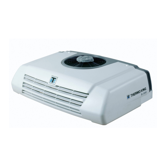
Thermo King B-100 Diagnostic Manual
Direct drive truck units esa, direct smart reefer microprocessor control system
Hide thumbs
Also See for B-100:
- Operator's manual (52 pages) ,
- Installation manual (40 pages) ,
- Operator's manual (76 pages)
Table of Contents


Need help?
Do you have a question about the B-100 and is the answer not in the manual?
Questions and answers