Sign In
Upload
Manuals
Brands
Thermo King Manuals
Automobile Accessories
V-200
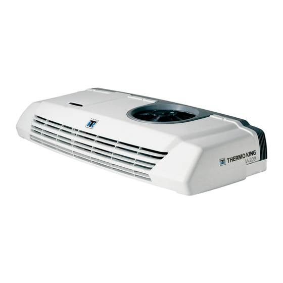
Thermo King V-200 Filter Drier Manuals
Manuals and User Guides for Thermo King V-200 Filter Drier. We have
3
Thermo King V-200 Filter Drier manuals available for free PDF download: Diagnostic Manual, Manual, Operator's Manual
Thermo King V-200 Diagnostic Manual (223 pages)
Direct Drive Truck Units ESA, Direct Smart Reefer Microprocessor Control System
Brand:
Thermo King
| Category:
Automobile Accessories
| Size: 4 MB
Table of Contents
Table of Contents
5
List of Figures
9
Safety Precautions
11
General Practices
13
Refrigerant
13
First Aid
13
Electrical Hazards
14
Handling the Batteries
14
Refrigeratin Oil
14
List of Figures
14
Safety Precautions
14
First Aid
14
Microprocessor Service
14
Welding
14
High Voltage
14
First Aid
15
Low Voltage
15
Typical Safety Decals
16
Direct Smart Reefer Microprocessor Notes
17
System Description
19
Block Diagram
21
General Description
23
In-Cab Control Box
23
Electronic Control Module (ECM)
24
Internal Layout of a Platform 1 Electronic Control Module
25
Electronic Control System Components
26
Microprocessors
26
PCB 1 and PCB 2
27
Printed Circuit Board I/O Connectors
28
System Fuses
37
System Relays
38
System Inputs
39
System Outputs
39
Unit Power
40
External Devices
40
Sensors
40
Switches and Transducers
40
Valves
41
Relays
42
Motors and Motor Protectors
42
Clutches
42
Contactors
43
Power Sources
43
Heaters
43
Systems and Equipment Covered
43
Software Description
45
Software Revisions and Changes
45
Unit Operation
45
Software Operation
47
Unit Operation
47
Cool Mode Operation - Standard Units
47
Cool Mode Operation - Electric Standby Units
48
Null Mode Operation - All Units
48
Heat Mode
48
Table of Contents
49
Menu Screens
49
Menu Flowcharts
51
DSR Main Menu Screens
53
DSR Hourmeters Menu Screens
54
DSR Information Menu Screens
55
DSR Installation (Guarded Access) Menu Screens
56
Programmable Features
57
Main Menu and Its Screens
57
Alarm Codes Displayed in the Main Menu
58
Accessing Additional Main Menu Screens
59
Hourmeters Menu and Its Screens
60
Information Menu and Its Screens
61
Leaving the Hourmeters Menu
61
Installation (Guarded Access) Menu and Its Screens
62
Operation
67
In-Cab Control Box Features
69
Keypad
69
Display
69
Keypad Keys and Buzzer
70
Understanding the Display
70
Display Icons
71
Reading a Typical Display
71
The Standard Display
72
Manual Start after an Alarm
72
Auto Start after an Alarm
73
Buzzers
74
Changing the Setpoint
75
Initiating a Manual Defrost Cycle
77
Checking the Software Revision
78
Viewing and Clearing Alarm Codes
79
To View Alarm Codes
79
To Clear Alarm Codes
79
DSR Μp Controller Alarm Codes
80
Diagnostics
81
DSR Μp Controller Notes
83
Electrostatic Discharge
83
DSR Μp Controller Diagnostic Hints
84
Part 1 - Corrective Actions as a Result of Alarm Codes
84
Part 2 - Corrective Actions as a Result of Other Symptoms
92
Important Diagnostic Considerations
92
Unit will Not Operate - Vehicle Power
93
Unit Not Cooling - Vehicle Power
94
Unit Not Heating - Vehicle Power
95
Unit will Not Defrost - Vehicle Power
96
Evaporator Fans Do Not Operate - Vehicle Power
98
Condenser Fans Do Not Operate - Vehicle Power
99
Unit will Not Operate - Battery Driven (B-100)
100
Unit Not Cooling - Battery Driven (B-100)
101
Unit will Not Defrost - Battery Driven (B-100)
102
Evaporator Fan will Not Operate - Battery Driven (B-100)
104
Condenser Fan will Not Operate - Battery Driven (B-100)
104
Unit will Not Operate - Electric Standby Power (Except B-100 20)
105
Unit Not Cooling - Electric Standby Power (Except B-100 20)
106
Unit Not Heating - Electric Standby Power
108
Unit will Not Defrost - Electric Standby Power (Except B-100 20)
111
Condenser Fans Do Not Operate - Electric Standby Power
113
Evaporator Fans Do Not Operate - Electric Standby Power
114
Unit will Not Operate - Electric Standby Power (B-100 20 Only)
115
Unit Not Cooling - Electric Standby Power (B-100 20 Only)
116
Unit will Not Defrost - Electric Standby Power (B-100 20 Only)
117
Condenser Fan will Not Operate - Electric Standby Power
119
Evaporator Fan will Not Operate - Electric Standby Power
120
In-Cab Air Conditioning Does Not Work (V-500 AC Only)
122
Erratic Operation
122
Service Procedures
125
Microprocessor Procedures
125
A02A Recording Existing Microprocessor Settings
125
A04A Microprocessor Setup
125
A12A ESD (Electrostatic Discharge) Procedures
125
A26A Welding on Units Equipped with Microprocessors
125
A28A Setting Unit Running Time Hourmeters
125
Printed Circuit Board Procedures
125
B02A Printed Circuit Board Removal and Replacement
125
Miscellaneous Procedures
125
Recording Existing Microprocessor Settings
127
Setup Sheet
129
Microprocessor Setup (Programming the DSR Microprocessor)
131
ESD (Electrostatic Discharge) Procedure
135
Welding on Units Equipped with Microprocessors
137
Setting Unit Running Time Hourmeters
139
Printed Circuit Board Removal and Replacement
141
Return Air Temperature Sensor Test
145
3 Wire Magnetic Door Switch
147
Document Control
148
Deutsch Connector Repair Using Pigtail
149
Splicing Connector and Harness Wires
151
Checking Harness Continuity
153
Removal/Replacement of the Filter/Fan in an Electronic Control Module
155
DSR Μp Controller Information
157
DSR Μp Controller Software Features
157
And Interchange
157
DSR Μp Controller Software - Features and Interchange
159
Schematics and Wiring Diagrams
161
Advertisement
Thermo King V-200 Manual (118 pages)
Brand:
Thermo King
| Category:
Refrigerator
| Size: 10 MB
Table of Contents
Table of Contents
5
List of Figures
9
Safety Precautions
11
General Practices
11
Refrigerant
11
Refrigeration Oil
11
Electrical Hazards
11
High Voltage
11
Low Voltage
12
Specifications
13
General
13
R-134A Refrigeration System
13
R-404A Refrigeration System
14
Electrical System
15
Maintenance Inspection Schedule
17
Unit Description
19
Introduction
19
Condenser
19
Evaporator
19
Compressor
19
Control Circuits
20
In-Cab Control Box
20
Oil Separator
20
Refrigerant
20
Liquid Injection System
20
Evaporator Drain Tube Heaters
20
Electric Standby Operation
20
Unit Features
21
Protection Features
21
Control Box
22
P.C. Board
22
Connectors
22
Fuses
22
Figure 1: Typical P.C. Board
22
Figure 2: P.C. Board Fuses
22
Common Relays
23
Standby Relays
23
Multi-Temp Relays
23
Figure 3: Fuse 4/1
23
Defrost Timer
24
Clutch Timer
24
EFR Selector
24
Unit Operation
24
Thermostat Operation
24
Figure 4: Thermostat Algorithm
24
Serial Number Locations
25
Figure 5: Condenser
26
Figure 6: Evaporator
26
Figure 7: Control Box Side of Model 20 Condenser
27
Figure 8: Refrigeration Component Side of Model 20 Condenser
28
Operating Instructions
29
Introduction
29
Description
29
Figure 9: M13 & 16 In-Cab Control Box
29
Figure 10: M-17 In-Cab Control Box
29
Figure 11: On/Off Key & LED
29
Figure 12: Celsius/Fahrenheit LED
29
Figure 13: Setpoint Key & Dial
30
Figure 14: Misc. Led's
30
Figure 15: Defrost Key & LED
30
In-Cab Control Box Operating Instructions (M-13, M-16, M-17)
31
Display Return Air (Box) Temperature
31
Display Setpoint Temperature
31
Enter Setpoint Temperature
31
Defrost Mode Operation (M-13, and M-16 Only)
31
Figure 16: On/Off Key and Defrost Key
31
Figure 17: Setpoint Key
31
Figure 18: Entering Setpoint
31
Unit Operation
32
Weekly Pretrip Inspection
32
Starting the Unit
32
After Start Inspection
32
Loading Procedure
32
Post Load Procedure
33
Tabl E of C Onten Ts
35
Electrical Maintenance
35
Trouble Shooting In-Cab Control Box M-13 and M-16
35
Figure 19: BLOCK DIAGRAM M-13, M-16
35
Trouble Shooting M-17 In-Cab Control Box (TC Units Only)
37
Figure 20: BLOCK DIAGRAM M-17
37
Defrost System
38
Defrost Components
38
Defrost Timer Settings
38
Figure 21: Defrost Timer
38
Manual Defrost Switch
39
Defrost Termination Switch
39
Defrost Relay
39
Defrost Solenoid Valve
39
Testing the Defrost System
39
Defrost Timer Test
39
Condenser Fan Pressure Switch (CFPS) R-134A Units Only
40
Testing CFPS
40
Liquid Injection System (R-404A Units Only)
40
Testing Liquid Injection Valve and Metering Orifice
40
Figure 22: Testing CFPS
40
Electric Standby Circuits
41
Refrigeration Maintenance
43
Refrigerant Charge
43
Charging the Refrigeration System
43
Figure 23: Charging Refrigeration System
43
Checking the Refrigerant Charge
44
Checking Compressor Oil Charge
45
High Pressure Cutout Switch (HPCO)
46
Low Pressure Cutout Switch (LPCO)
46
Figure 24: High Pressure Cutout Manifold
46
Cleanup Procedure for Small Truck Units
47
Figure 25: Connecting Flushing Compressor to Unit
47
Refrigeration Service Operations
49
Compressor
49
Figure 26: Refrigeration Systems in Model 20 Configurations
49
Condenser Coil
50
Drier
50
High Pressure Cutout and Condenser Fan Pressure Switches
50
Solenoid Valves
50
Oil Separator
51
Liquid Injection Metering Orifice
51
Figure 27: Engine Driven Compressor
51
Testing the Liquid Injection Solenoid Valve and Metering Orifice
52
Discharge Check Valve (Model 20 Only)
52
Testing the Discharge Check Valve
52
Figure 28: Check Valve Assembly
53
Check Valve Repair
54
Check Valve Replacement
54
Evaporator Coil
54
Expansion Valve Assembly
55
Low Pressure Cutout Switch
55
Figure 29: Location of Expansion Valve Bulb
55
Figure 30: Completely Wrap Bulb with Tape
55
Suction Receiver Tank (Heat Option Only)
56
Suction Pressure Regulator Valve (TC Units Only)
56
In-Line Check Valves (TC Units Only)
56
Installation
56
Replacing Refrigerant Hoses (Speedy Clip System)
57
Figure 31: Cutting the Hose
57
Figure 32: Fitting the Clips
57
Figure 33: Lubricating the Cylinder of the Fitting
57
Figure 34: Manually Inserting the Fitting
57
Figure 35: Positioning the Clamp
57
Figure 36: Fitting the Clips
57
Figure 37: Tightening both Clips
57
Structural Maintenance
59
Unit Inspection
59
Evaporator Coil
59
Condenser Coil
59
Unit Mounting Bolts
59
Figure 38: Condenser
59
Figure 39: Evaporator
59
Clutch Maintenance
61
Clutch Removal
61
Clutch Test
61
Figure 40: Remove Center Bolt
61
Figure 41: Remove Drive Plate
61
Figure 42: Remove Snap Ring and Cover
62
Figure 43: Remove Pulley
62
Figure 44: Remove Coil
62
Figure 45: Inspect Components
62
Clutch Installation
63
Figure 46: Install Coil
63
Figure 47: Install Pulley
63
Figure 48: Install Cover and Snap Ring
63
Figure 49: Install Shims and Drive Plate
63
Figure 50: Remove Shaft Seal Cover
64
Figure 51: Remove Shaft Seal
64
Shaft Seal Cover and Shaft Seal: Removal and Installation
64
Figure 52: Inspect Shaft Seal
65
Figure 53: Place Guide on Shaft
65
Figure 54: Place Shaft Seal on Guide
65
Figure 55: Press Seal into Cylinder Head
65
Figure 56: Install Shaft Seal Cover
66
Figure 57: Proper Shaft Seal Cover Position
66
Figure 58: Clutch Remover P/N 204-806
66
Figure 59: Compressor Holder P/N 204-807
66
Special Tools
66
Figure 60: Clutch Installation Kit P/N 204-890
67
Figure 61: Snap Ring Pliers P/N 204-808
67
Figure 62: Shaft Seal Kit P/N 204-805
67
List of Figures
64
System Compressor and Oil
68
Checking the Oil Level
68
Figure 63: Pulley Arbor P/N 204-804
68
Figure 64: Draining the Oil
68
Belt Tensions
69
Engine Driven Compressor Belt and Pulleys
69
Electric Standby Compressor Belt
69
Over-The-Road Mechanical Diagnosis
71
Electric Standby Mechanical Diagnosis
73
Electric Standby Service Checks
76
Refrigeration Diagnosis Chart
77
Index
79
Diagram Index
81
Thermo King V-200 Operator's Manual (60 pages)
with Direct Smart Reefer
Brand:
Thermo King
| Category:
Automobile Accessories
| Size: 10 MB
Table of Contents
Table of Contents
6
Safety Precautions
9
Danger, Warning, Caution, and Notice
9
General Safety Practices
10
Automatic Start/Stop Operation
11
Battery Installation and Cable Routing
11
Refrigerant
13
Refrigerant Oil
14
First Aid
14
Safety Decals
16
Service
16
Operation
17
High Voltage
17
Condenser and Evaporator Fans
18
Remote Start of the Unit
18
Refrigerant
19
Type Certification
20
Unit Description
21
Standard Unit Features
22
Options
22
System Components
22
Compressor(S)
22
Condenser
23
Evaporator
23
Electronic Control System
24
Description
24
Unit Controls
26
Standby Operation (Models 20 and 50 Only)
27
Electrical System
28
Fuses
28
Pharma
29
Operating Instructions
30
General Operation
30
Starting the Unit
31
Engine Operation
31
Electric Standby Operation
31
Standard Display
32
Single Temperature Units
32
Multi-Temperature Units
32
Entering Setpoint Temperature
33
Single Temperature Units
33
Multi-Temperature Units
33
Compartment Selection
35
Initiating the Evaporator Manual Defrost Cycle
37
Initiating the Condenser Manual Defrost Cycle
38
Units Only)
38
Alarms
40
Manual Start
40
Auto Start
40
Buzzers
41
Alarm Code Descriptions DSR
42
Clearing Alarm Codes
43
Viewing Information Screens
43
Main Menu
43
Hourmeter Menu
43
Loading and Inspection Procedures
44
Post-Start Inspection
44
Loading Procedure
44
Post Load Procedure
44
Specifications
46
Refrigeration System
46
Compressor
46
Electrical Control System
46
Electric Motor (Model 50)
50
Tracking
50
Warranty
52
Inspection and Service Intervals
53
Weekly Pre-Trip Checks
53
Weekly Pretrip Inspection
53
Weekly Post-Trip Checks
54
Inspection and Service Schedules
54
Service Record
55
Warranty Inspection
55
Preventive Maintenance
55
Serial Number Locations
56
Recover Refrigerant
57
Advertisement
Advertisement
Related Products
Thermo King V-200s
Thermo King V220 Series
Thermo King V-200 10
Thermo King V-200 20
Thermo King V-220 10
Thermo King V-220 20
Thermo King V-220 MAX 10
Thermo King V-300
Thermo King V-520 RT 20
Thermo King V-800 20
Thermo King Categories
Refrigerator
Automobile Accessories
Air Conditioner
Heat Pump
Control Systems
More Thermo King Manuals
Login
Sign In
OR
Sign in with Facebook
Sign in with Google
Upload manual
Upload from disk
Upload from URL