
Related Manuals for Thermo King V-500 Series


Summary of Contents for Thermo King V-500 Series
- Page 1 V-500 Series TK 51859-1-MM (Rev. 1, 05/05) Copyright© 2004 Thermo King Corp., Minneapolis, MN, USA. Printed in USA.
- Page 2 TK 5955 The information in this manual is provided to assist owners, operators and service people in the proper upkeep and maintenance of Thermo King units. The above manuals may be purchased from your local Thermo King dealer. This manual is published for informational purposes only and the information so provided should not be considered as all-inclusive or covering all contingencies.
- Page 3 Ester compressor oil in tightly sealed containers. If Polyol Ester oil becomes contaminated with moisture or standard oils, dispose of properly–DO NOT USE. When servicing Thermo King R-134a or R-404A units, use only those service tools certified for and dedicated to R134a/R-404A refrigerant and Polyol Ester compressor oils.
-
Page 5: About This Manual
About This Manual Purpose The purpose of this manual is to provide general maintenance information necessary to maintain the climate control unit at peak operating standards. This includes safety information, unit information such as bills of material and kit numbers, general unit information, maintenance procedures and related information (such as wiring and schematic diagrams), and some diagnostic and troubleshooting information. -
Page 6: Before You Call Thermo King Service
About This Manual Before you Call Thermo King Service! Who to call: Your Thermo King Service Representative. Before you call Thermo King Service, have the following information on hand: • Bill of Material (usually located on the unit serial plate) •... -
Page 7: Table Of Contents
Before you Call Thermo King Service! ........ - Page 8 Table of Contents Operating Instructions ..............33 Introduction .
- Page 9 Table of Contents Compressor Maintenance ..............55 Refrigerant Handling Instructions .
- Page 10 Table of Contents...
-
Page 11: List Of Figures
List of Figures Figure 1: P.C. Board Fuses ..............26 Figure 2: Fuse 4/1 . - Page 12 List of Figures Figure 51: Place Shaft Seal on Guide ............65 Figure 52: Press Seal Into Cylinder Head .
-
Page 13: Safety Precautions
Safety Precautions General Practices Auto Start/Stop 1. Always wear goggles or safety glasses. CAUTION: The unit may start Refrigerant liquid, refrigeration oil, and automatically and at any time when the battery acid can permanently damage the eyes. unit On/Off switch is in the On position. 2. -
Page 14: Refrigeration Oil
Safety Precautions Refrigeration Oil The following procedures must be rigidly adhered to when servicing units to avoid microprocessor Observe the following precautions when working damage or destruction. with or around synthetic or polyol ester refrigerant 1. Disconnect all power to the unit. oil: 2. -
Page 15: Welding Of Units Or Truck Bodies
Safety Precautions Welding of Units or Truck Bodies Precautions When electric welding is to be performed on any 1. Be certain the Unit On/Off switch is turned portion of the temperature control unit, truck or Off before connecting or disconnecting the truck chassis when the temperature control unit is standby power plug. -
Page 16: Low Voltage
Safety Precautions If the victim must be removed from a live circuit, pull the victim off with a non-conductive material. Use the victim’s coat, a rope, wood, or loop your belt around the victim’s leg or arm and pull the victim off. -
Page 17: Model Systems (System Designations)
Model Systems (System Designations) Thermo King Model V-500 Truck Refrigeration Systems System Schematic, Wiring System Designation Power Pack Install Kit Refrig Number Diagrams V-500-10 920387 8800002 R-134a 1E24520, 1E24518 V-500-20 3PH 920388 085060 8800002 R-134a 1E18884, 1E24443 V-500-20 1PH 920388... - Page 18 Model Systems (System Designations)
-
Page 19: Specifications
Specifications Electrical System Fuses Fuse 1: Evaporator Fan Motor (EF1) 15 amps Fuse 2: Evaporator Fan Motor (EF2) 15 amps Fuse 3: Engine-driven Compressor Clutch Coil, Condenser 15 amps Solenoid Valve Coil (heating option), Hot Gas Solenoid Valve Coil Fuse 5: Condenser Fan Motor (CFM1) 15 amps Fuse 6: Condenser Fan Motor (CFM2) 15 amps... -
Page 20: Refrigerant System
8.0 lbs (3.6 kg) R-134a Defrost Method: Hot gas Defrost Timer: Initiation Interval Adjustable, 1 hour to 10 hours Termination Interval Termination is not timed. Defrost is terminated by Klixon switch. CAUTION: Failure to use correct Thermo King recommended oil will invalidate your warranty. -
Page 21: Belt Tension (Using Tool P/N 204-427)
Specifications Belt Tension (Using Tool P/N 204-427) Field Reset Engine Driven Compressor Belt Check vehicle manufacturer specifications AC Electric Motors Voltage Phase Frequency Full Load Current 208/230 60 Hz 14.1 Amps 208/230 60 Hz 16.0 Amps Electric Standby Power Requirements Supply Circuit Breaker 30 amp Extension Cord Size... - Page 22 Specifications...
-
Page 23: General Description
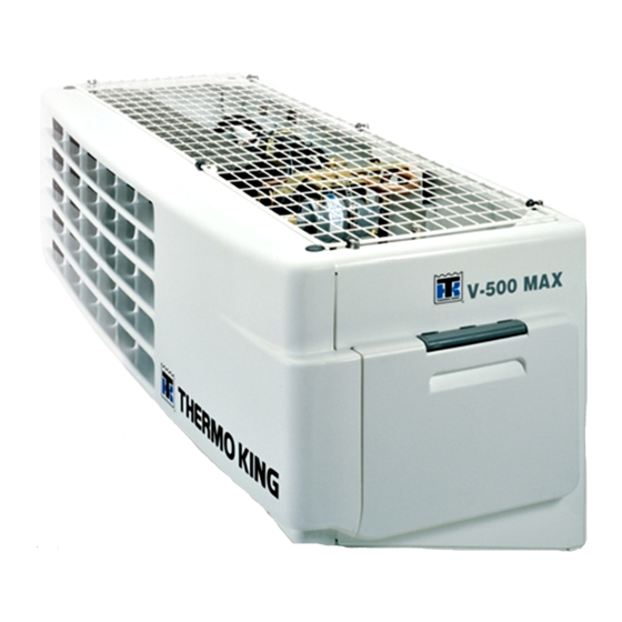
General Description Introduction Condenser The Thermo King V-500 10/20 and V-500 MAX The condenser has a unique design that allows it truck refrigeration systems are two piece units. to be mounted horizontally on the roof, or on the The unit is designed for medium-sized trucks and front of the truck box. -
Page 24: Control Circuits
General Description Control Circuits the liquid injection switch opens, the liquid injection solenoid closes and refrigerant no longer The control circuits operate on 12V supplied by flows through the liquid injection system. the truck batteries for engine operation. On standby operation, the power is rectified from an Evaporator Drain Tube Heaters AC transformer. -
Page 25: Unit Features
General Description Unit Features When the discharge pressure falls below the switch’s closing pressure, the switch closes to • M-13 In-Cab Control Box with Digital LED restart the unit. The closing pressure for Thermometer (Standard) R-134a units is 200 psi (1379 kPa). The closing pressure for R-404A units is 375 psi •... -
Page 26: Control Box
P.C. Board Fuse 2: Protects the evaporator fan motor (EFM2) from possible overload. All Printed Circuit Boards manufactured by Thermo King can be easily identified by the Part Fuse 3: Protects: Number stamped on them. • The engine-driven compressor clutch coil. -
Page 27: Common Relays
General Description Common Relays Overload Relay (OL) The Overload Relay is located in the Control Box The common relays are located on the P.C. Board. below the P. C. Board. Power Relay (PR) The Overload Relay switches off the unit when the current draw through the AC Motor is The Power Relay is energized when the In-Cab excessive. -
Page 28: Thermostat Operation
General Description Thermostat Operation Defrost The defrost cycle can be initiated any time the Cool evaporator coil temperature is below 36 F (2.2 C). Defrost is initiated automatically by the defrost The thermostat energizes the (PR) at box timer, or manually by pressing the manual defrost temperatures higher than 5.4 F (3.0 C) above switch. -
Page 29: Serial Number Locations
General Description Serial Number Locations Nameplate located on the back CONDENSER: inside wall of condenser frame. Nameplate ENGINE DRIVEN COMPRESSOR: located on compressor body. The engine driven compressor is located in the truck engine compartment. Nameplate located on STANDBY COMPRESSOR: compressor body. -
Page 30: Figure 5: Condenser Electric And Capacitor Boxes (Model 20)
General Description AMA512 AMA532 PC Board Heat Option Contactor Motor Contactor Capacitor Box Figure 5: Condenser Electric and Capacitor Boxes (Model 20) -
Page 31: Figure 6: Evaporator
General Description AMA514 AMA513 Evaporator Fans Temperature Sensor Expansion Valve Defrost Switch Figure 6: Evaporator... -
Page 32: Figure 7: Evaporator With Hot Water And Electric Heat Options
General Description AMA525 Hot Water Heat Defrost Coil High Temperature Limit Switch Electric Heat Element Air Temperature Sensor Figure 7: Evaporator with Hot Water and Electric Heat Options... -
Page 33: Operating Instructions
Operating Instructions 5. Fahrenheit LED Indicator. When on, it indicates the temperature being displayed is in degrees fahrenheit. AJA1772 Figure 8: M13 In-Cab Control Box Introduction Unit operation is controlled with a in-cab control box, which is mounted in the truck cab. It includes AJA1803 an on-off switch, manual defrost switch, thermometer, thermostat, thermostat adjustment,... -
Page 34: In-Cab Control Box Operating Instructions
Operating Instructions In-Cab Control Box Operating Instructions Display Return Air (Box) Temperature During normal operation (unit is ON and cooling), the ON LED Indicator, the Unit Operation LED and Celsius/Fahrenheit LED Indicator should be ON; the return air (box) temperature should be AJA1806 displayed on the screen. -
Page 35: Figure 14: On/Off Key And Defrost Key
Operating Instructions AJA1808 On/Off Key Manual Defrost Key Figure 14: On/Off Key and Defrost Key AJA1809 Setpoint Key Figure 15: Setpoint Key AJA1807 Setpoint Adjustable Dial Setpoint Key Figure 16: Entering Setpoint... -
Page 36: Unit Operation
1. Start the truck engine. 4. Products should be pre-cooled before loading. 2. Press the On-Off switch on the In-Cab Control Thermo King units are designed to maintain Box, the ON/OFF LED must go ON. loads at the temperature at which they were 3. - Page 37 Operating Instructions 3. Start the unit. 4. Half an hour after loading, defrost the unit by momentarily pressing the Manual Defrost switch. If the coil temperature has dropped below 36 F (2.2 C), the unit will defrost. The defrost cycle should stop automatically. Weekly Post Trip Checks 1.
- Page 38 Operating Instructions...
-
Page 39: Maintenance Inspection Schedule
Maintenance Inspection Schedule NOTE: Thermo King reserves the right to deny NOTE: See the appropriate chapter in this warranty coverage on claims due to lack of maintenance manual for instructions on how to maintenance or neglect. Claims in question must correctly perform required maintenance. - Page 40 Maintenance Inspection Schedule...
-
Page 41: Electrical Maintenance
Electrical Maintenance Maintenance Inspection Schedule Semi- Procedures Weekly Monthly Annual Annually Check defrost initiation and termination. • • Check thermostat cycle sequence. • • Check operation of protection shutdown circuits. • • Check thermostat and thermometer calibration in 0 C •... -
Page 42: Trouble Shooting In-Cab Control Box M-13 And M-16
Electrical Maintenance Trouble Shooting In-Cab Control Box M-13 and M-16 Before starting this trouble shooting, verify that the In-Cab Control Box 12/24V selector is placed in the correct position and check the ground circuit through Pin 9 Connector C-9. AJA1775 Figure 18: Block Diagram M-13, M-16 IMPORTANT: This trouble shooting only covers In-Cab Control Box functions and should not be... -
Page 43: Defrost System
Electrical Maintenance SYMPTOMS REMEDY Defrost cycle is not initiated when the Manual 1st. Box temperature must be higher than Setpoint Defrost Switch is pressed. temperature; unit must be in cool mode. 2nd. Evaporator coil temperature must be lower than 36.0 ± 5.4 F (2.2 ± 3.0 C) (defrost termination switch closed). -
Page 44: Defrost Termination Switch
Electrical Maintenance 36 F (2.2 C). completing the defrost circuit to ground and preparing the electrical system for the defrost cycle. When the unit does shift into a defrost cycle, the evaporator fan stops, and heat from the hot refrigerant gas melts the frost from the evaporator coil. -
Page 45: Defrost Timer Test
Electrical Maintenance Condenser Fan Pressure If the unit fails to defrost, place a jumper wire between the 12 and CH wires at the defrost Switch (CFPS) R-134a Units termination switch. Press the manual defrost Only switch. When the condenser head pressure rises above If the unit shifts to defrost, the defrost 180 ±... -
Page 46: Testing Liquid Injection Solenoid Valve And Metering Orifice
Electrical Maintenance switch closes to open the liquid injection solenoid 1. Check the AC line voltage and the transformer valve. When the discharge temperature falls fuse. If the AC line voltage is acceptable and below 200 ± 5 F (93 ± 3 C), the switch opens to the transformer fuse is intact, go to step 2. -
Page 47: Refrigeration Maintenance
2. Connect the center hose of the gauge manifold to the manifold of an evacuation station. The 6. After the additional hour of evacuation, close use of Thermo King Evacuation Station the valve at the evacuation pump, stop the P/N 204-725 is recommended. -
Page 48: Checking The Refrigerant Charge
Refrigeration Maintenance 8. When the system reaches 500 microns, close b. Connect the electric power receptacle to the vacuum valve at the evacuation station an appropriate electric power supply. Start manifold. The system is now ready to charge. and run the unit in cool on electric operation for a minimum of 15 minutes. -
Page 49: Checking Compressor Oil Charge
Refrigeration Maintenance partially cover the condenser grille on the NOTE: A suction line oil separator can be front of the unit to create the desired head improvised by installing a suction filter pressure. upside down in the suction line near the compressor. -
Page 50: High Pressure Cutout Switch (Hpco)
Refrigeration Maintenance High Pressure Cutout Switch 450 psig (3102 kPa) on R-404A units, the High Pressure Cutout will stop the (HPCO) compressor. The high pressure cutout switch is located on a NOTE: The discharge pressure should never discharge line inside the condenser unit. If the be allowed to exceed a pressure of 450 psig discharge pressure rises above 300 psig (3102 kPa). -
Page 51: Cleanup Procedure For Small Truck Units
Refrigeration Maintenance Cleanup Procedure for Small 2. Make sure that the oil trap is correctly installed. Truck Units 3. Recover the contaminated refrigerant from the system. 4. Remove the lines from the compressors (engine driven and standby). 5. Flush each compressor using the flushing compressor and an HFC refrigerant. - Page 52 Refrigeration Maintenance Putting the Unit Back Into Operation 1. Replace the check valve (or check valve seats). 2. Install a new oil separator. 3. Install a new liquid injection orifice. 4. Install a new drier. 5. Install a new expansion valve. 6.
-
Page 53: Structural Maintenance
Structural Maintenance Maintenance Inspection Schedule Semi- Procedures Weekly Monthly Annual Annually Visually inspect unit and refrigerant hoses for fluid • • • • leaks. Visually inspect unit for damaged, loose or broken • • • • parts. Clean defrost drains. •... - Page 54 Structural Maintenance...
-
Page 55: Compressor Maintenance
Compressor Maintenance Refrigerant Handling Refrigerant Recovery Instructions Some refrigeration system refrigerant compounds are chlorofluorocarbons, and therefore may be Refrigerant Handling Safety damaging to the earth’s ozone layer. Consequently, the release of refrigerant into the DANGER: Explosion Hazard! Never atmosphere must be avoided. Whenever throw or strike refrigerant bottles and refrigerant is to be removed from the refrigeration never handle the packing carton roughly. -
Page 56: Compressor Installation Guidelines
Compressor Maintenance Compressor Installation Compressor Installation Position Guidelines The compressor should be installed on the vehicle within the range shown below. If installed outside Compressor Handling this range, the compressor will be adversely affected. This compressor is equipped with a CAUTION: Do not strike the compressor pressure feed lubrication system that cannot or turn it upside down. -
Page 57: Compressor Installation
Compressor Maintenance Compressor Installation The compressor is mounted on the truck engine using a special mounting bracket. The side to side mounting angle of the compressor must remain ± 45 degrees from the horizontal. The forward to backward angle must be within ± 10 degrees of horizontal. -
Page 58: Mounting Compressors
Compressor Maintenance Mounting Compressors CAUTION: Do not open a refrigeration Clearance between the compressor mounting system unnecessarily. This increases the supports and its bracket must be less than 0.004 chance of contamination. inches (0.10 mm). Use shims as necessary to adjust this clearance. -
Page 59: Checking Compressor Oil
Compressor Maintenance Checking Compressor Oil Oil Check Interval Unlike engine oil, it is not necessary to frequently check or change the compressor oil. However it is necessary to check and replenish or replace the compressor oil in the following cases: •... -
Page 60: Draining And Replacing Oil
Compressor Maintenance Draining and Replacing Oil When a System Becomes Contaminated A severely contaminated system may be indicated by black oil in the compressor. If severe contamination occurs, it will be necessary to flush the complete system. If flushing is required, use industry approved materials. -
Page 61: Clutch Test
NOTE: Make sure the proper tools are available before performing maintenance procedures. Refer to “Special Tools” at the end of this chapter for the tools required. Contact your local Thermo King dealer for further information. Removal 1. Remove the center armature bolt. Snap Ring... -
Page 62: Inspection
Compressor Maintenance 2. Pulley Assembly: If the pulley’s contact CAUTION: To avoid damaging the pulley surface is excessively grooved due to groove, the puller claws should be hooked slippage, both the pulley and armature plate into, not under, the pulley groove. must be replaced. -
Page 63: Figure 42: Install Pulley
Compressor Maintenance 3. Install the pulley assembly using the installer and a hand press. Snap Ring Figure 42: Install Pulley Cover (If Equipped) 4. Install the cover (if equipped) and the snap Figure 44: Install Cover and Snap Ring ring using external ring pliers. 5. -
Page 64: Clutch Run In
Compressor Maintenance 7. Check the air gap with a feeler gauge. The air 2. Use the seal remover (from the shaft seal kit) gap should be 0.016 to 0.031 in. (0.4 to 0.8 to remove the shaft seal cover. Turn the seal mm). -
Page 65: Inspection
Compressor Maintenance Inspection 4. Place the shaft seal over the seal guide and slide the seal into the front cylinder head. The shaft seal should not be reused. Always use a new shaft seal when reassembling the compressor. Be extremely careful that the lip of the new shaft seal is not scratched or damaged in any way. -
Page 66: Seal Cover Installation (When Equipped)
Compressor Maintenance 8. Press the snap ring using the installing end of 3. Use the seal installer (from the shaft seal kit) the remover until a “Click” is heard. to press the shaft seal cover into the cylinder. NOTE: When installing the snap ring, the NOTE: Position the shaft seal cover as shown in chamfered edge of the snap ring must face the illustration. -
Page 67: Figure 56: Remove Body Bolts
Compressor Maintenance 4. Remove the six body bolts securing the head 6. Remove the O-ring from the front cylinder using a socket wrench. head and the remove all the gasket material from the front cylinder head. Figure 56: Remove Body Bolts O-ring 5. -
Page 68: Inspection
Compressor Maintenance 8. To remove the rear cylinder head alternately 10. Remove the valve plate and suction valve tap the projections on the circumference of the from the cylinder shaft assembly and remove rear head with a screwdriver and a plastic all the gasket material from the valve plate. -
Page 69: Reassembly
Compressor Maintenance Reassembly 3. Install the rear valve plate on the rear suction valve. Rear Cylinder Head CAUTION: Be careful not to mistake the 1. Place the cylinder shaft assembly on the bench front valve plate for the rear valve plate. with the rear side up. -
Page 70: Figure 67: Front Suction Valve
Compressor Maintenance Front Cylinder Head 1. Place the cylinder shaft assembly on the bench with the front side up. 2. Install the front suction valve so that it aligns with alignment pin. CAUTION: Ensure that the valve is aligned with the valve escape groove of each cylinder. -
Page 71: Compressor Leak Test Procedure
Compressor Maintenance Compressor Leak Test 9. Install the oil drain plug with a new O-ring, thinly coated with clean compressor oil, and Procedure torque it to 9.4 to 10.8 ft-lb (13 to 15 N•m). When a compressor is repaired it should be checked prior to installation. -
Page 72: Special Tools
Compressor Maintenance Special Tools 8932e Figure 73: Shaft Seal Kit P/N 204-805 8932f Figure 72: Pulley Arbor P/N 204-804 8932a Figure 74: Clutch Remover P/N 204-806... -
Page 73: Belt Tensions
Compressor Maintenance Belt Tensions Engine Driven Compressor Belt and Pulleys Correct pulley alignment and proper belt tension are very important factors in compressor installation. The compressor clutch must be perfectly aligned with the engine pulley and any 8932b auxiliary idler or belt adjustment pulley Figure 75: Compressor Holder P/N 204-807 components. - Page 74 Compressor Maintenance...
-
Page 75: Over-The-Road Mechanical Diagnosis
Over-the-Road Mechanical Diagnosis If desired box temperature cannot be obtained 9. AIR IN SYSTEM. Air is not condensable. Its during engine driven compressor operation, any presence in the system increases head of the following may be indicated: pressure. When the compressor is stopped, air will gather at the high point of the high side. - Page 76 Over-the-Road Mechanical Diagnosis • Lack of compressor lubrication on installation and startup • Excessive compressor speed (maximum speed 3,000 rpm)
-
Page 77: Electric Standby Mechanical Diagnosis
Electric Standby Mechanical Diagnosis Condition Possible Cause Remedy Compressor does not run Improperly wired Check wiring against diagram Low line voltage Check line voltage, determine location of voltage drop Relay contacts not closing Check by operating manually. Replace relay if defective Fuses blown Replace fuses Open circuit in motor winding... - Page 78 Electric Standby Mechanical Diagnosis Condition Possible Cause Remedy Unit operates long or Shortage of refrigerant Repair leak and recharge continuously Discharge valve leaking Replace leak Thermostat faulty Repair or replace Dirty condenser Clean condenser Air in system Evacuate and recharge system Compressor inefficient Replace compressor Plugged expansion valve...
-
Page 79: Electric Standby Service Checks
Electric Standby Mechanical Diagnosis Condition Possible Cause Remedy Head pressure too low Refrigerant shortage Repair leak and recharge Compressor suction or discharge Replace valve valve inefficient Noisy unit Insufficient compressor oil Add oil to proper level Mounting bolts loose Tighten Refrigerant flooding back Adjust oil level or refrigerant charge. - Page 80 Electric Standby Mechanical Diagnosis Electric Standby Service Checks 3.Compressor hums but does not run. a.Check for locked rotor. b.Check for worn bearings. Replace if necessary. c.Check for locked compressor and repair. d.Check power source for single phasing (on three phase units). e.Check capacitors (on single phase units).
-
Page 81: Refrigeration Diagnosis Chart
Refrigeration Diagnosis Chart POSSIBLE CAUSES • • Overcharge of refrigerant • • • • • • • Shortage of refrigerant • • • • • • • • No refrigerant • Air through condenser too hot (ambient) • Air flow through condenser restricted (dirty) •... - Page 82 Refrigeration Diagnosis Chart...
-
Page 83: Index
Index Numerics Condenser Fan Pressure Switch (CFPS) R-134a Units Only 45 17845 Connectors 26 Headline01 contents, manual, description of 5 Thermostat Operation 28 Control 24 26590 Control Box 26 Numbered Control Circuits 24 3. Entering the Setpoint Temperature. 34 curbside, definition 6 curbside/roadside terminology, explained 6 about this manual 5 After Start Inspection 36... - Page 84 Index Liquid Injection System 24 liquid injection system 45 Testing The Defrost System 44 Liquid Injection System (R-404A Units Only) 45 Trouble Shooting M-17 In-Cab Control Box (TC Units Loading Procedure 36 Only) 43 Low Pressure Cutout Switch (LPCO) 48, 50 low pressure cutout switch (LPCO) 50 Unit Features 25 Unit Mounting Bolts 53...
- Page 85 Wiring, Refrigeration and Schematic Diagrams Index Dwg No. Drawing Title Page 1E24520 V-500-10, V-500 MAX-10 Schematic Diagram 1E24518 V-500-10, V-500 MAX-10 3PH Wiring Diagram 1E18884 V-500-20 3PH, V-500 MAX-20 3PH Schematic Diagram 1E24443 V-500-20 3PH, V-500 MAX-20 3PH Wiring Diagram 1E24519 V-500-20 1PH, V-500-20 1PH Schematic Diagram 1E24517...
- Page 86 Wiring, Refrigeration and Schematic Diagrams Index...
- Page 87 V-500-10, V-500 MAX-10 Schematic Diagram...
- Page 88 V-500-10, V-500 MAX-10 3PH Wiring Diagram, page 1 of 2...
- Page 89 V-500-10, V-500 MAX-10 3PH Wiring Diagram, page 2 of 2...
- Page 90 V-500-20 3PH, V-500 MAX-20 3PH Schematic Diagram...
- Page 91 V-500-20 3PH, V-500 MAX-20 3PH Wiring Diagram, page 1 of 3...
- Page 92 V-500-20 3PH, V-500 MAX-20 3PH Wiring Diagram, page 2 of 3...
- Page 93 V-500-20 3PH, V-500 MAX-20 3PH Wiring Diagram, page 3 of 3...
- Page 94 V-500-20 1PH, V-500-20 1PH Schematic Diagram...
- Page 95 V-500-20 1PH, V-500-20 1PH Wiring Diagram, page 1 of 3...
- Page 96 V-500-20 1PH, V-500-20 1PH Wiring Diagram, page 2 of 3...
- Page 97 V-500-20 1PH, V-500-20 1PH Wiring Diagram, page 3 of 3...
- Page 98 V-500-10 Refrigeration Diagram, page 1 of 2...
- Page 99 V-500-10 Refrigeration Diagram, page 2 of 2...
- Page 100 V-500 MAX 10 Refrigeration Diagram, page 1 of 2...
- Page 101 V-500 MAX 10 Refrigeration Diagram, page 2 of 2...
- Page 102 V-500 20 Refrigeration Diagram, page 1 of 2...
- Page 103 V-500 20 Refrigeration Diagram, page 2 of 2...
- Page 104 V-500 MAX 20 Refrigeration Diagram, page 1 of 2...
- Page 105 V-500 MAX 20 Refrigeration Diagram, page 2 of 2...
- Page 106 V-500 MAX Outline Diagram, page 1 of 3...
- Page 107 V-500 MAX Outline Diagram, page 2 of 3...
- Page 108 V-500 MAX Outline Diagram, page 3 of 3...
Need help?
Do you have a question about the V-500 Series and is the answer not in the manual?
Questions and answers
ايهاب النجار