Table of Contents
Advertisement
Quick Links
Advertisement
Table of Contents

Subscribe to Our Youtube Channel
Related Manuals for L-Acoustics K3i


Summary of Contents for L-Acoustics K3i
- Page 1 owner's manual (EN)
- Page 2 Document reference: K3i owner's manual (EN) version 1.0 Distribution date: April 22, 2021 © 2021 L-Acoustics. All rights reserved. No part of this publication may be reproduced or transmitted in any form or by any means without the express written consent of the publisher.
-
Page 3: Table Of Contents
Line source with low-frequency element..................... 33 Additional downll element........................35 Rigging procedures............................37 General principles...........................37 Tools..............................39 Flying..............................40 Flying a K3i array with K3i-BUMP....................40 Adding a pullback with K3i-RIGBAR....................46 Rigging a Kara IIi downll array under a K3i array with KARAIIi-DOWNK3i........49... - Page 4 Ceiling-mounting a K3i array with K3i-CEILINGBRACKET................53 Stacking a K3i array on K3i-TILTBRACKET....................58 Securing a screen........................... 62 Connection to LA amplied controllers........................ 63 Cabling..............................64 Specications..............................68 APPENDIX A: Recommendation for speaker cables....................83 APPENDIX B: Specications for custom rigging system..................84...
-
Page 5: Safety
Respect the Working Load Limit (WLL) of third party equipment. L-Acoustics is not responsible for any rigging equipment and accessories provided by third party manufacturers. Verify that the Working Load Limit (WLL) of the suspension points, chain hoists and all additional hardware rigging accessories is respected. - Page 6 Any unauthorized maintenance operation will void the product warranty. Before sending a product to L-Acoustics for maintenance, save all user presets to les using LA Network Manager. This marking indicates that this product should not be disposed of with other household waste throughout the EU.
-
Page 7: Introduction
Requiring only two channels of amplication, K3i is a high value solution that provides large-format concert sound in compact and lightweight construction to facilitate most integration scenarios. K3i is highly weather-resistant as standard and can be color-matched to melt into any venue decor, indoor or outdoor. -
Page 8: System Components
Refer to the LA4X / LA8 / LA12X owner's manual for detailed instructions about the whole cabling scheme, including modulation cables and network. Rigging elements K3i-TILTBRACKET Fastening bracket with angles for K3i K3i-CEILINGBRACKET Ceiling fastening bracket with angles for K3i K3i-LINK Rigging plate for K3i K3i-ENDLINK End rigging plate for K3i... -
Page 9: System Component Illustrations
System components K3i-RIGBAR Rigging bar and pullback for K3i KARAIIi-DOWNK3i Interface for ying Kara IIi below K3i CLAMP250 Clamp certied for 250 kg Screens K3i-SCREEN Acoustically transparent front screen for K3i Software applications Soundvision 3D acoustical and mechanical modeling software LA Network Manager Software for remote control and monitoring of amplied controllers... - Page 10 System components KARAIIi-DOWNK3i CLAMP250 Screens K3i-SCREEN Software applications Soundvision LA Network Manager K3i owner's manual (EN) version 1.0...
-
Page 11: Electro-Acoustical Description
The K3i enclosure features an adjustable horizontal directivity system. Using the adjustable ns, horizontal directivity can be adjusted with four different settings: 70° / 110° symmetric or 90° asymmetric. A specic K3i preset must be used for each directivity setting. - Page 12 Electro-acoustical description 90° settings (preset [K3 90]) K3i owner's manual (EN) version 1.0...
- Page 13 Electro-acoustical description 110° setting (preset [K3 110]) Mixed settings K3i owner's manual (EN) version 1.0...
-
Page 14: Directivity
-120 -140 -160 -180 1 000 10 000 Frequency (Hz) Dispersion angle diagram of a K3i array with 70° ns setting, using lines of equal sound pressure at -3 dB, -6 dB, -12 -100 -120 -140 -160 -180 1 000... -
Page 15: Preset Description
OUT 4 IN A 0 dB 0 ms [KS28_60_C] [KS28_60_Cx] [KS21_60_C] [KS21_60_Cx] loudspeaker elements outputs channels routing gain delay polarity mute OUT 1 IN A 0 dB 0 ms OUT 2 OUT 3 OUT 4 K3i owner's manual (EN) version 1.0... -
Page 16: Connectors
Electro-acoustical description Connectors 2 × 4-point terminal blocks with push-in connection Internal pinout for L-Acoustics 2-way active enclosures terminal block points Transducer connectors LF + LF - HF + HF - K3i owner's manual (EN) version 1.0... -
Page 17: Rigging System Description
K3i is compatible with two types of rigging plate kits: standard rigging plates (K3i-LINK) end rigging plates (K3i-ENDLINK) K3i-LINK can be used to add an inter-element angle of 0.25°, 1°, 2°, 3°, 4°, 5°, 7.5° or 10° between two K3i. 0.25° 3°... - Page 18 It is recommended to use the rigging report from Soundvision to prepare the enclosures. Rigging screws Only use the rigging screws provided by L-Acoustics. Do not use the placeholder screws for rigging. Always put the placeholder screws back in place to avoid leaks.
-
Page 19: Rigging Elements
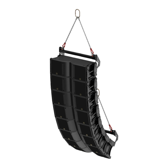
Rigging system description Rigging elements K3i-BUMP K3i-BUMP is a rigging frame designed for ying K3i. K3i-BUMP can be used as the main lifting accessory for ying arrays of K3i. K3i owner's manual (EN) version 1.0... - Page 20 Rigging system description K3i-BUMP is secured to the array with four M8x35 rigging screws and M8 nuts (provided). With K3i-LINK, the splay angle with K3i can be set to 0°, 2.5°, 5°. To calculate the site angle of the rst enclosure, subtract the splay angle from the site angle of K3i-BUMP.
-
Page 21: K3I-Bar
Seventeen (17) holes are available on the K3i-BAR, which can be attached as a rear or a front extension and in position A or B, thus offering a total of 68 discrete positions for pick-up points. The pick-up points are compatible with Ø19 mm shackles WLL 3.25 t (two provided). -
Page 22: K3I-Rigbar
K3i-RIGBAR Secured at the bottom of the array, K3i-RIGBAR can be used as a pullback either with K3i-BUMP combined with K3i-BAR or another K3i-RIGBAR as the main lifting accessory, to provide a lightweight solution for ying up to 16 K3i. - Page 23 Maximum limit with CLAMP250 CLAMP250 has a WLL (Working Load Limit) of 250 kg / 550 lb. It can support an array of up to 6 K3i. For an hybrid array, check the total weight of the array in Soundvision.
-
Page 24: Karaiii-Downk3I
KARAIIi-DOWNK3i KARAIIi-DOWNK3i is a rigging interface for a Kara IIi array under a K3i array. The inter-element angle between the K3i array and the Kara IIi array can be set to 0.25°, 1°, 2°, 3°, 4°, 5°, 7.5°, or 10°. - Page 25 Rigging system description KARAIIi-DOWNK3i is assembled with six M6x19 screws (provided). KARAIIi-DOWNK3i is secured to the K3i array with four M8x35 screws, and to the Kara IIi array with four M6x19 screws (provided). K3i owner's manual (EN) version 1.0...
-
Page 26: K3I-Tiltbracket
Rigging system description K3i-TILTBRACKET K3i-TILTBRACKET is a set of four fastening brackets with site angle adjustment for improved stability on a stack of K3i. K3i-ENDLINK is required on the top enclosure. The angles can be set at the rear for downwards site angles or the front for upwards site angles. - Page 27 Rigging system description When used at the front, it is not possible to use K3i-SCREEN. K3i-TILTBRACKET cannot be used to mount K3i under the ceiling. Refer to K3i-CEILINGBRACKET (p.28). K3i owner's manual (EN) version 1.0...
-
Page 28: K3I-Ceilingbracket
Rigging system description K3i-CEILINGBRACKET K3i-CEILINGBRACKET is a set of four fastening brackets with site angle adjustment to mount K3i under the ceiling. K3i-ENDLINK is required on the top enclosure. The angles can be set at the rear for downwards site angles or the front for upwards site angles. -
Page 29: K3I-Screen
Fasteners for ceiling-mounting. Select screw length and anchors applicable to the ceiling properties. K3i-CEILINGBRACKET is not allowed for a stack of K3i. Always secure a stacked array to the ground using K3i- TILTBRACKET to ensure stability of the array. K3i-SCREEN The K3i system features an acoustically transparent front screen suitable for own or stacked arrays. -
Page 30: Mechanical Safety
Mechanical safety Mechanical safety Flown congurations The K3i rigging system complies with 2006/42/EC: Machinery Directive. It has been designed following the guidelines of BGV-C1. 2006/42/EC: Machinery Directive species a safety factor of 4 against the rupture. The own deployments described in this manual achieve a safety factor of 4 or more. - Page 31 Soundvision calculations are based on usual environmental conditions. A higher safety factor is recommended with factors such as extreme high or low temperatures, strong wind, prolonged exposition to salt water, etc. Always consult a rigging specialist to adopt safety practices adapted to such a situation. K3i owner's manual (EN) version 1.0...
-
Page 32: Loudspeaker ConGurations
Loudspeaker congurations Line source Deployed as a line source, the system operates over the nominal bandwidth of the K3i enclosure, with an adjustable horizontal directivity. The [K3 70], [K3 90], and [K3 110] presets allow for a reference frequency response in long throw applications. Each preset is dedicated to a horizontal directivity setting. -
Page 33: Line Source With Low-Frequency Element
Loudspeaker congurations Line source with low-frequency element A K3i line source can be deployed with additional subwoofer enclosures to extend the bandwidth in the low-end or increase sub-low resources. The [K3 70], [K3 90], and [K3 110] presets allow for a reference frequency response in long throw applications. Each preset is dedicated to a horizontal directivity setting. - Page 34 [K3] + [KS21_60] K3 = 0 ms KS21 = 0 ms [K3] + [KS21_60_C] K3 = 5.5 ms KS21 = 0 ms [K3] + [KS21_60_Cx] K3 = 5 ms KS21 = 0 ms K3i owner's manual (EN) version 1.0...
-
Page 35: Additional DownLl Element
Loudspeaker congurations Additional downll element All K3i system congurations can be combined with an additional Kara IIi line source downll system. This allows an extension of the vertical coverage to the closer audiences. Kara IIi The Kara IIi enclosures are driven by the LA4X / LA8 / LA12X amplied controllers. - Page 36 Loudspeaker congurations Using the Kara IIi system Refer to the Kara IIi owner's manual for the operating modes of Kara IIi as a main system. K3i owner's manual (EN) version 1.0...
-
Page 37: Rigging Procedures
This introduction provides general principles applicable for all congurations. Screws Rigging screws Only use the rigging screws provided by L-Acoustics. Do not use the placeholder screws for rigging. Always remove the relevant placeholder screws before securing the rigging plates. Risk of acoustic leaks Do not remove the placeholder screws from the bottom rear inserts (A, B or C) that are not used. - Page 38 • Place the rigging plate side with the label towards the enclosure. • At the top of K3i-LINK rear: the bottom hole on the linking section is positioned towards the rear of the enclosure. • At the bottom: the shape of the rigging plate is parallel to the edge of the enclosure and the holes and inserts are aligned.
-
Page 39: Tools
Stacking enclosures Fastening brackets Always secure a stacked array to the ground using K3i-TILTBRACKET to ensure the stability of the array. When stacking two enclosures, the top enclosure must be slightly lifted to align the inserts with the rigging plate holes. -
Page 40: Flying
Rigging procedures Flying Flying a K3i array with K3i-BUMP Type of deployment own array Rigging accessories K3i-BUMP 2 Ø19 mm shackles WLL 3.25 t (provided) K3i-LINK Screws and fasteners 4 M8x35 rigging screws and M8 nuts (provided) Tools electric screwdriver with torque selector... - Page 41 5°, 2.5°, 0°, -2.5°, -5°, -7.5°, -10°, -12.5°, -15° It is recommended to use the rigging report from Soundvision to prepare the enclosures. b) Secure K3i-LINK with the top and middle screws on both sides. 2. Position K3i-BUMP on top of the enclosure.
- Page 42 2.5° 5° 4. Optionally, secure a K3i-BAR on K3i-BUMP to extend the site angle capability, in position A or B. Use the provided rigging axes and nuts, and secure using two 19 mm hex bit. Insert the safety pins. 19 mm K3i-BAR can be attached as a rear or a front extension.
- Page 43 Hold the enclosure at the bottom until the rigging plates are secured. 7. Secure the second enclosure under the array: a) Lift the second enclosure under the array. The plates of the lower enclosure must be on top of the plates of the upper enclosure. K3i owner's manual (EN) version 1.0...
- Page 44 Apply a torque of 7 N.m. 0.25° 3° 1° 2° 4° 5° 7.5° 10° 7 N.m 8. Tighten all the screws on the supporting enclosure. 9. Repeat step (p.43) to (p.44) as necessary to complete the array. K3i owner's manual (EN) version 1.0...
- Page 45 To add a pullback, refer to Adding a pullback with K3i-RIGBAR (p.46). To add a downll, refer to Rigging a Kara IIi downll array under a K3i array with KARAIIi-DOWNK3i (p.49). To add screens, refer to Securing a screen (p.62).
-
Page 46: Adding A Pullback With K3I-Rigbar
When ying an array, use available holes to implement a secondary safety. Procedure 1. Prepare an array of K3i. Refer to Flying a K3i array with K3i-BUMP (p.40). 2. Attach K3i-RIGBAR to a motor using one Ø12 mm shackle WLL 1 t. K3i owner's manual (EN) version 1.0... - Page 47 Rigging procedures 3. Secure K3i-RIGBAR to the bottom enclosure. Use the enclosure rear hole (insert B). 4. Tighten the screws of the bottom enclosure on both sides. Apply a torque of 7 N.m. 7 N.m K3i owner's manual (EN) version 1.0...
- Page 48 The pullback angle must not exceed a 90° negative site angle. The chains must be as vertical as possible. Optionally, the K3i array can be own using K3i-RIGBAR at the front or at the back of the top enclosure. Follow the procedure from Flying a K3i array with K3i-BUMP (p.40) using K3i-ENDLINK on the top enclosure.
-
Page 49: Rigging A Kara Iii DownLl Array Under A K3I Array With Karaiii-Downk3I
Rigging procedures Rigging a Kara IIi downll array under a K3i array with KARAIIi-DOWNK3i Type of deployment own array Rigging accessory KARAIIi-DOWNK3i Screws and fasteners 4 M8x35 rigging screws (provided) 10 M6x19 rigging screws (provided) Tools electric screwdriver with torque selector... - Page 50 5 N.m This step requires three operators. Hold the enclosure at the bottom until the rigging plates are secured. 5. Secure Kara IIi under the array: a) Lift Kara IIi under the K3i array. K3i owner's manual (EN) version 1.0...
- Page 51 Select the appropriate holes and inserts depending on the selected angle. Apply a torque of 7 N.m. 0.25° 3° 1° 2° 4° 5° 7.5° 10° 6. Tighten the screws of the bottom K3i enclosure on both sides. Apply a torque of 7 N.m. K3i owner's manual (EN) version 1.0...
- Page 52 9. Add more Kara IIi with KARAIIi-LINK as necessary to complete the array. 10. Check that all screws are secured and tightened. What to do next To add screens to K3i, refer to Securing a screen (p.62). To add screens to Kara IIi, refer to the Kara IIi owner's manual.
-
Page 53: Ceiling-Mounting A K3I Array With K3I-Ceilingbracket
-25° with the angle at the rear with the angle at the front When used at the front, it is not possible to use K3i-SCREEN. Fasteners for ceiling-mounting. Select screw length and anchors applicable to the ceiling properties. Model the array in Soundvision and check the loads on rigging in the Mechanics view. - Page 54 Rigging procedures Procedure 1. Secure K3i-CEILINGBRACKET to the ceiling using four M10 screws and fasteners. Fasteners for ceiling-mounting. Select screw length and anchors applicable to the ceiling properties. Model the array in Soundvision and check the loads on rigging in the Mechanics view.
- Page 55 Hold the enclosure at the bottom until the rigging plates are secured. 4. Secure the enclosure on K3i-CEILINGBRACKET with rigging screws: a) Secure the enclosure to the short bracket. K3i-CEILINGBRACKET must be on top of the plates of the enclosure. K3i owner's manual (EN) version 1.0...
- Page 56 Rigging procedures b) Secure the enclosure to the long bracket. Select the appropriate angle. 5. Depending on the selected deployment, add more K3i enclosures, one at a time: a) On the additional enclosure, remove the relevant placeholder screws, refer to step (p.54).
- Page 57 Rigging procedures 6. Tighten the bottom screws on the last enclosure. Apply a torque of 7 N.m. 7 N.m What to do next To secure screens, refer to Securing a screen (p.62). K3i owner's manual (EN) version 1.0...
-
Page 58: Stacking A K3I Array On K3I-Tiltbracket
When used at the front, it is not possible to use K3i-SCREEN. Fastening brackets Always secure a stacked array to the ground using K3i-TILTBRACKET to ensure the stability of the array. Risk of falling objects Verify that no unattached items remain on the product or assembly. - Page 59 Risk of acoustic leaks Do not remove the placeholder screws from the bottom rear inserts (B or C) that are not used. 3. Secure the top and middle screws of K3i-LINK on both sides. K3i owner's manual (EN) version 1.0...
- Page 60 On the additional enclosure, remove the relevant placeholder screws, refer to step (p.59). b) Secure the top and middle screw of the link on both sides. For the last enclosure at the top of the stacked array, use K3i-ENDLINK, otherwise use K3i-LINK. K3i owner's manual (EN) version 1.0...
- Page 61 Tighten all the screws on the supporting enclosure. Apply a torque of 7 N.m. 7. Check that all the screws are secured and tightened. What to do next To secure screens, refer to Securing a screen (p.62). K3i owner's manual (EN) version 1.0...
-
Page 62: Securing A Screen
Risk of bending screen xing tabs Always use the self-sticking washers for securing a screen when there are no rigging plates on the enclosure. 2. Secure the screen. Apply a torque of 5 N.m. K3i owner's manual (EN) version 1.0... -
Page 63: Connection To La AmpliEd Controllers
Refer to the Kara IIi owner's manual for the cabling schemes of Kara IIi with LA2Xi. For passive loudspeakers, the value corresponds to the number of enclosures in parallel on the output. For active loudspeakers, the value corresponds to the number of sections in parallel on the output. K3i owner's manual (EN) version 1.0... -
Page 64: Cabling
This procedure describes how to connect the input cable to the enclosure. If the enclosure must be connected in parallel, remove the protective plug from the second cable gland and proceed identically for both cables. Procedure 1. On the connector sealing plate, remove the sealing nut from the cable gland. K3i owner's manual (EN) version 1.0... - Page 65 Connection to LA amplied controllers 2. Insert the cable through the sealing nut and the cable gland. 3. Strip the wires of the cable. 30 mm 10 mm 4 x 2.5 mm cable K3i owner's manual (EN) version 1.0...
- Page 66 4. Push the wires into the terminals. If necessary, use a small tool in the hole next to the terminal to unlock it. 5. Secure the connector sealing plate to the connector plate. 3 N.m K3i owner's manual (EN) version 1.0...
- Page 67 Connection to LA amplied controllers 6. Tighten the sealing nut. What to do next To remove the cables use the small tool to unlock the terminals and pull on the wires. K3i owner's manual (EN) version 1.0...
-
Page 68: SpeciCations
Pantone 426 C pure white RAL 9010 custom RAL code on special order IP55 Peak level measured at 1 m under free eld conditions using pink noise with crest factor 4 (preset specied in brackets). K3i owner's manual (EN) version 1.0... - Page 69 Specications K3i dimensions 907 mm / 35.7 in K3i owner's manual (EN) version 1.0...
- Page 70 Pantone 426 C pure white RAL 9010 custom RAL code on special order IP55 Peak level measured at 1 m under free eld conditions using pink noise with crest factor 4 (preset specied in brackets). K3i owner's manual (EN) version 1.0...
- Page 71 Specications Kara IIi dimensions 701 mm / 27.6 in 252 mm / 9.9 in 409 mm / 16.1 in K3i owner's manual (EN) version 1.0...
- Page 72 Peak level at 1 m under half space conditions using pink noise with crest factor 4 (preset specied in brackets). KS28 dimensions 702 mm / 27.6 in 1340 mm / 52.8 in 1351 mm / 53.2 in K3i owner's manual (EN) version 1.0...
- Page 73 Pantone 426 C pure white RAL 9010 custom RAL code on special order IP55 Peak level at 1 m under half space conditions using pink noise with crest factor 4 (preset specied in brackets). K3i owner's manual (EN) version 1.0...
- Page 74 Specications KS21i dimensions 752 mm / 29.6 in 602 mm / 23.7 in K3i owner's manual (EN) version 1.0...
- Page 75 K3i-BUMP specications Description Flying frame for K3i 2 Ø19 mm shackles WLL 3.25 t Weight (net) 21 kg / 45 lb Material high grade steel with anti-corrosion coating K3i-BUMP dimensions 913 mm / 35.9 in K3i owner's manual (EN) version 1.0...
- Page 76 Specications K3i-RIGBAR specications Description Rigging bar and pullback for K3i 2 Ø12 mm shackles WLL 1 t Weight (net) 10 kg / 20 lb Material high grade steel with anti-corrosion coating K3i-RIGBAR dimensions 961 mm / 37.9 in 968 mm / 38.1 in...
- Page 77 2 Ø19 mm shackles WLL 3.25 t 2 Ø25 mm axis, M12 nuts, and safety pins Weight (net) 17 kg / 36 lb Material high grade steel with anti-corrosion coating K3i-BAR dimensions 1014 mm / 39.9 in K3i owner's manual (EN) version 1.0...
- Page 78 Specications KARAIIi-DOWNK3i specications Description Interface for ying Kara IIi below K3i Weight (net) 10 kg / 22 lb Material high grade steel with anti-corrosion coating KARAIIi-DOWNK3i dimensions 117 mm / 4.6 in 944 mm / 37.2 in K3i owner's manual (EN) version 1.0...
- Page 79 Specications K3i-TILTBRACKET specications Description Fastening bracket with angles for K3i Weight (net) 1.3 kg / 2.2 lb Material high grade steel with anti-corrosion coating K3i-TILTBRACKET dimensions 70 mm / 2.8 in 60 mm / 2.4 in 35 mm / 1.4 in 60 mm / 2.4 in...
- Page 80 Specications K3i-CEILINGBRACKET specications Description Ceiling fastening bracket with angles for K3i Weight (net) 1 kg / 2.2 lb Material high grade steel with anti-corrosion coating K3i-CEILINGBRACKET dimensions 61 mm / 2.4 in 60 mm / 2.4 in 35 mm / 1.4 in 60 mm / 2.4 in...
- Page 81 Specications K3i-SCREEN specications Description Acoustically transparent front screen for K3i Weight (net) 2.4 kg / 4.4 lb Material high grade steel with anti-corrosion coating K3i-SCREEN dimensions 921 mm / 36.3 in K3i owner's manual (EN) version 1.0...
- Page 82 CLAMP250 specications Description Clamp certied for 250 kg Weight (net) 1.8 kg / 4 lb Material high grade steel with anti-corrosion coating CLAMP250 dimensions 167 mm / 6.6 in 103 mm / 4.1 in K3i owner's manual (EN) version 1.0...
-
Page 83: Appendix A: Recommendation For Speaker Cables
8 Ω load 4 Ω load 2.7 Ω load Use the more detailed L-Acoustics calculation tool to evaluate cable length and gauge based on the type and number of enclosures connected. The calculation tool is available on our website: https://www.l-acoustics.com/en/installation/tools/... -
Page 84: Appendix B: SpeciCations For Custom Rigging System
346.9 mm / 14 in 4 x M8 inserts per side Weight without rigging plates K3i: 36 kg / 78 lb Screws • The grade and threaded length of screws used on the enclosures depend on the design of the metal sheets on the array. - Page 85 L-Acoustics 13 rue Levacher Cintrat - 91460 Marcoussis - France +33 1 69 63 69 63 - info@l-acoustics.com www.l-acoustics.com...
Need help?
Do you have a question about the K3i and is the answer not in the manual?
Questions and answers