Table of Contents
Advertisement
Advertisement
Table of Contents

Related Manuals for L-Acoustics 112XT


Summary of Contents for L-Acoustics 112XT
- Page 1 Version 1.1 February 2003 L-ACOUSTICS XT LINE 112XT, 115XT OPERATOR MANUAL...
-
Page 2: Foreword
FOREWORD Thank you for purchasing the 112XT or 115XT sound reinforcement system. This manual is intended to provide you with the information you require to install and operate your XT loudspeaker enclosure in a wide variety of professional sound reinforcement applications. - Page 3 L-ACOUSTICS XT Manual V1.1 2/11/2003...
-
Page 4: Table Of Contents
5.4 SAFETY RULES ............................40 6. XT SYSTEM OPERATION .........................41 6.1 RECOMMENDED MAINTENANCE PROCEDURES ..................41 6.2 SPARE PARTS.............................. 42 7. SPECIFICATIONS ..........................43 7.1 112XT ELEMENT SPECIFICATIONS ......................43 7.2 115XT ELEMENT SPECIFICATIONS ......................47 L-ACOUSTICS XT Manual V1.1 2/11/2003... -
Page 5: List Of Figures
Table 1: Load and Power Ratings for 112XT ....................12 Table 2: Recommended power amplification and MLS switch settings for 112XT low section ..... 13 Table 3: Recommended power amplification and MLS switch settings for 112XT high section ....13 Table 4: Recommended MLS switch settings for powering 112XT.............. -
Page 6: Introduction
British manufacturer for studio monitoring applications – to the best of our knowledge, L-ACOUSTICS was the first manufacturer to use coaxial technology in professional sound reinforcement applications and the current XT line is a continuation of the heritage that was introduced in 1989. -
Page 7: The Xt System
The coaxial performance of the 112XT and 115XT loudspeaker enclosures provide the basic starting tools for distributed sound reinforcement design. 1. THE XT SYSTEM The XT line consists of: 112XT, 115XT loudspeaker enclosures, XT rigging accessories and SB115, SB118, SB218 or dV-SUB subwoofers. - Page 8 XT RIGGING ACCESSORIES (7) ETR112XT Adjustable U-Bracket for ceiling, wall or scaffold mounting of the 112XT in either horizontal or vertical orientations (8) CPL112XT Coupling adapter bars used in conjunction with ETR112XT to array two 112XT enclosures vertically with independent tilt adjustment for both enclosures...
-
Page 9: Figure 1: Xt System Components
ETR112XT ETR115XT CPL115XT CPL112XT PION2 XTLIFTBAR F-CABLE DO7 F-LINK CABLE DO.7 Figure 1: XT System Components L-ACOUSTICS XT Manual V1.1 2/11/2003... -
Page 10: Xt Overview
MONITOR presets are derived under half-space measurement conditions. A variety of 3-way presets are provided for use of the 112XT or 115XT with SB115, SB118, SB218 or dV-SUB subwoofers. Standard 3W presets utilize a complimentary 100 Hz crossover point for the XT and its companion subwoofer and are recommended for closely coupled applications. -
Page 11: 112Xt Specifications
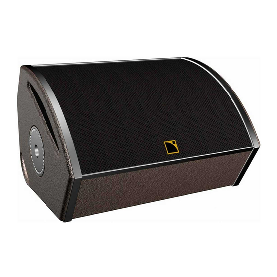
4-pin Neutrik Speakon connectors. The 112XT has a truncated wedge shape with a curved front profile. Dimensions are 54 cm (21.3 in) high, 41 cm (16.1 in) wide at the front of the enclosure, 16.5 cm (6.5 in) wide at the rear of the enclosure and 37.5 cm (14.8 in) deep. -
Page 12: 115Xt Specifications
The 115XT loudspeaker is used with an approved digital processor with OEM factory presets for active 2-way operation or 3-way operation in conjunction with additional subwoofers (L-ACOUSTICS SB115, SB118, SB218 or dV-SUB). -
Page 13: Powering Xt
2. POWERING XT It is important that power amplifiers with sufficient power are used to power the 112XT or 115XT since headroom is less likely to damage loudspeaker components than clipping. Apart from normal standards regarding construction, protection, cooling and damping factor that are expected of any... -
Page 14: Table 2: Recommended Power Amplification And Mls Switch Settings For 112Xt Low Section
(0 dB) (-2 dB) (-4 dB) L-ACOUSTICS LA amplifier MLS switch settings for powering the 112XT are summarized in Table 4 and Figure 4 shows the location of MLS switches on the LA24a and LA48a rear panel. L-ACOUSTICS XT Manual V1.1... -
Page 15: Powering 115Xt
0 dB -2 dB -4 dB Figure 4: MLS switches on the rear panel of L-ACOUSTICS LA24a, LA48a amplifiers 2.2 POWERING 115XT Continuous (rms) and peak power handling ratings for the 115XT are as follows: LF Section: 45 volts rms long term (pink noise with 6 dB crest factor) -
Page 16: Table 6: Recommended Power Amplification And Mls Switch Settings For 115Xt Low Section
Based on these specifications, recommended L-ACOUSTICS LA power amplifier specifications and MLS switch settings are summarized below in Tables 6 and 7. Table 6: Recommended power amplification and MLS switch settings for 115XT low section 115XT LOW SECTION AMPLIFIER OUTPUT POWER... -
Page 17: Table 9: Output Power Ratings And Mls Switch Settings For L-Acoustics Laa Amplifiers
1380 1665 2130 2700 2 ohms Stereo (2 channel) 1200 1400 1550 1700 2 ohms Stereo (2 channel) 1660 2000 2400 2900 Table 9: Output Power Ratings and MLS Switch Settings for L-ACOUSTICS LAa Amplifiers L-ACOUSTICS XT Manual V1.1 2/11/2003... -
Page 18: Connectors And Cables
4 mm conductor cross-section (11 gauge). SP25 cables can be used for 25 meter cable runs to power a 4 ohm load (2 x 112XT or 115XT enclosures in parallel) while maintaining a damping factor greater than 20. -
Page 19: General Description Of Xt Presets
Alternatively, when XT enclosures are flown and subwoofers are ground stacked, 3WX presets can be employed where an 80 Hz low pass filter is applied to the subwoofers and 112XT or 115XT low frequency response extends to 55 or 50 Hz, respectively. -
Page 20: Guidelines Regarding System Protection
540 W and assuming 32 dB amplifier gain, these power ratings correspond to limit thresholds of 0 dBu (135 W) and +6 dBu (540 W). As standard, the 112XT HF limiter threshold is set to +3 dBu (3 dB less than the peak power handling). -
Page 21: Xt Preset Libraries
3.4 XT PRESET LIBRARIES As described in Section 3.2, three types of 2-way presets for 112XT and 115XT are provided (FRONT, FILL and MONITOR) while two types of 3-way presets are available for the use of XT enclosures with L-ACOUSTICS SB115, SB118, SB218 or dV-SUB subwoofers (3W and 3WX). - Page 22 L-ACOUSTICS V7 0902 PRESETS for XTA DP 226 PRESET NAME PGM TYPE OUT 1 (Source) OUT 2 (Source) OUT 3 (Source) OUT 4 (Source) OUT 5 (Source) OUT 6 (Source) ARCS 2W LO 3-way stereo FULL (A) ARCS LOW (A)
-
Page 23: Figure 5: L-Acoustics Preset Library For Xta Dp224
L-ACOUSTICS V7 0902 PRESETS for XTA DP 224 PRESET NAME PGM TYPE OUT 1 (Source) OUT 2 (Source) OUT 3 (Source) OUT 4 (Source) ARCS 2W LO 2-way stereo ARCS LO (A) ARCS HI (A) ARCS LO (B) ARCS HI (B) -
Page 24: Figure 7: L-Acoustics Preset Library For Bss Fds-334 Minidrive
115XT LO (A) 115XT HI (A) dV-SUB (B) 115XT 3WX dV-SUB 3-way (A) + SUB (B) dV-SUB (A) 115XT LO (A) 115XT HI (A) dV-SUB (B) Figure 7: L-ACOUSTICS preset library for BSS FDS-334 Minidrive L-ACOUSTICS XT Manual V1.1 2/11/2003... -
Page 25: Figure 8: L-Acoustics Preset Library For Bss Fds-336 Minidrive
115XT LOW (B) 115XT HI (B) 115 X dVS 3(A)+3(B) dV-SUB (A) 115XT LOW (A) 115XT HI (A) dV-SUB (B) 115XT LOW (B) 115XT HI (B) Figure 8: L-ACOUSTICS preset library for BSS FDS-336 Minidrive L-ACOUSTICS XT Manual V1.1 2/11/2003... -
Page 26: Figure 9: L-Acoustics Preset Library For Bss Fds-366 Omnidrive Compact Plus
115XT HI (C) 115XT MON 2(A)+2(B)+2(C) 115XT LOW (A) 115XT HI (A) 115XT LOW (B) 115XT HI (B) 115XT LOW (C) 115XT HI (C) Figure 9: L-ACOUSTICS preset library for BSS FDS-366 Omnidrive Compact Plus L-ACOUSTICS XT Manual V1.1 2/11/2003... -
Page 27: Sound Design
XT enclosures with subwoofers, use the correct power amplification and use the correct OEM factory preset. In general terms, 112XT or 115XT enclosures are intended for distributed sound reinforcement or small to medium-scale Front-Of-House (FOH) applications. FOH applications include: theatres, clubs, multi-purpose venues or corporate events. -
Page 28: Arraying Xt Enclosures
Figure 12 shows SPL mappings at octave band frequencies for two XT enclosures with a spacing of 0.5 meters. Uneven coverage above 500 Hz demonstrates the comb filtering interference effects that arise due to path length differences as a function of listener position. L-ACOUSTICS XT Manual V1.1 2/11/2003... -
Page 29: Figure 12: Spl Mappings At Octave Band Frequencies For Two Xt Enclosures With 0.5 Metre Spacing
500 Hz 1 kHz 2 kHz 4 kHz Figure 13: SPL mappings at octave band frequencies for two XT enclosures with 3 metre spacing (distributed system corresponding to the “best” case shown in Figure 14) L-ACOUSTICS XT Manual V1.1 2/11/2003... -
Page 30: Figure 14: General Guidelines For Arraying Xt Enclosures
500 Hz 1 kHz 2 kHz 4 kHz Figure 15: SPL mappings at octave band frequencies for four XT enclosures with 0.5 metre spacing (arrayed system corresponding to the “avoid” case shown in Figure 14). L-ACOUSTICS XT Manual V1.1 2/11/2003... -
Page 31: Predicting Xt Coverage
4) The optimum spacing between delay loudspeakers will depend on the coverage angle of the enclosure (90 degrees for 112XT, 80 degrees for 115XT) as well as the distance to first members of the audience. Center-to-center overlap will provide the most uniform coverage (see also 4.5.1). -
Page 32: Complementary Fill
As for overhead distributed or delay systems, the optimum spacing between XT enclosures will depend on the coverage angle of the enclosure (90 deg for 112XT, 80 deg for 115XT) and the distance to the first members of the audience. Center-to-center overlap will provide the most uniform coverage and separate time alignment delay taps for front fill enclosures can further assist in improving image localization. -
Page 33: Front-Of-House (Foh) Applications
XT enclosures are used as a close proximity fill enclosure. For 3-way operation of 112XT or 115XT loudspeaker enclosures with SB115, SB118, SB218 or dV- SUB subwoofers there are two different types of preset available: 1) 3W presets optimize the power... -
Page 34: Table 11: Nominal Floor Monitor Distance And Monitor Separation Versus Performer Height
4 ft 7 in Apart from separation and distance to the performer, the last issue to consider when using 112XT or 115XT as floor monitors in paired configurations is whether to angle them in towards the performer. Although it looks more “rock and roll” and gives the performer the impression of having more SPL, it is generally not advised to angle wedges in but to use them with the front faces parallel to each other. -
Page 35: Using Xt With Subwoofers
Since the XT and its companion subwoofer are physically coupled for side fill or drum monitoring applications, 3W presets are recommended since complimentary 100 Hz crossover filtering optimizes the power bandwidth for the subwoofer and the 112XT or 115XT low section (please see Section 4.8 for further details). -
Page 36: Combining Xt With Subwoofers
3WX presets have an 80 Hz LR24 low pass filter for the subwoofers and an overlapping LR24 high pass filter for the XT low section (45 Hz HPF for 112XT, 40 Hz HPF for 115XT). Due to the overlap in the operating bandwidths of the sub and low sections, subwoofer polarity may have to be inverted due to the phase shift of overlapping crossover filters (depending on the selected preset and how the subwoofers are driven, i.e., via AUX send or with the same signal as sent to the XT system) -
Page 37: Figure 17: Illustration Of Subwoofer Time Alignment
XT enclosure or driven via discrete AUX send. Following time alignment, subwoofer polarity is a parameter to experiment with in order to obtain the best results. L-ACOUSTICS XT Manual V1.1 2/11/2003... -
Page 38: Installation Procedures
ETR112XT and ETR115XT are optional accessory U-Brackets for ceiling, wall or scaffold mounting of the 112XT or 115XT, respectively, in either horizontal or vertical orientations. Three mount holes are available on the center section of the ETR112XT and ETR115XT for bracket mounting. Pole mount adapter plates on 112XT and 115XT enclosures allow for 10 degree angular resolution. -
Page 39: Cpl112Xt, Cpl115Xt Coupling Adapter Bar Attachment
5.2 CPL112XT, CPL115XT COUPLING ADAPTER BAR ATTACHMENT The CPL112XT or CPL115XT coupling adapter bars are optional accessories that can be used in conjunction with ETR112XT or ETR115XT U-brackets to array two 112XT or 115XT enclosures vertically (with independent tilt adjustment for both enclosures). -
Page 40: Figure 19: Cpl112Xt, Cpl115Xt Coupling Adapter Installation Procedure
(6) Lower 112XT installed rotate, facilitating installation of the lower 112XT (7) Attach lower locking pins on both sides of the lower 112XT to (8) Attach lower locking pins on both sides of the lower 112XT to facilitate angling of the CPL112XT... -
Page 41: Xtliftbar Attachment
5 pick points available for tilt adjustment. Pick point holes (from front to back) provide tilt angles of +14, +7, 0, -7 or -14 degrees for either 112XT or 115XT. (2) The XTLIFTBAR mounting stud mates with 112XT or 115XT... -
Page 42: Xt System Operation
A while output channels 4, 5, 6 correspond to Sub, XT low, XT high for input B. Power up the DSP unit and select the appropriate preset for 2-way operation (FRONT, FILL or MONITOR) or 3-way operation (3W or 3WX for 112XT or 115XT plus SB115, SB118, SB218, dV- SUB subwoofers). -
Page 43: Spare Parts
L-ACOUSTICS for warranty examination. b) LF Service The 12” or 15'' loudspeaker components of the coaxial assemblies used in the 112XT and 115XT are not field-serviceable. For field service, the entire coaxial assembly should be removed and replaced. -
Page 44: Specifications
7. SPECIFICATIONS 7.1 112XT ELEMENT SPECIFICATIONS Frequency Response Frequency response: 65 – 18k Hz (± 3 dB) (FRONT preset) Usable bandwidth: 55 – 18k Hz (-10 dB) Sensitivity (2.83 Vrms at 1 m) 98.5 dB SPL (65 – 1k Hz) (2.83 Vrms at 1 m) -
Page 45: Figure 21: 112Xt Line Drawing
Figure 21: 112XT Line Drawing L-ACOUSTICS XT Manual V1.1 11-02-03... -
Page 46: Figure 22: 112Xt + Etr112Xt Line Drawing
Figure 22: 112XT + ETR112XT Line Drawing Figure 23: 112XT + XTLIFTBAR Line Drawing L-ACOUSTICS XT Manual V1.1 11-02-03... -
Page 47: Figure 24: 112Xt + Etr112Xt + 112Cplxt Line Drawing (0 Degree)
Figure 24: 112XT + ETR112XT + 112CPLXT Line Drawing (0 degree) Figure 25: 112XT + ETR112XT + 112CPLXT Line Drawing (30 degrees) L-ACOUSTICS XT Manual V1.1 11-02-03... -
Page 48: 115Xt Element Specifications
2x 4-pin Neutrik speakon Material 18 mm, 30 mm Baltic birch plywood (sealed, screwed and rabbeted angles) Finish Maroon-gray™ Grill Black epoxy perforated steel with acoustically transparent foam Rigging Integrated flying hardware, handles and pole mount socket L-ACOUSTICS XT Manual V1.1 11-02-03... -
Page 49: Figure 26: 115Xt Line Drawing
Figure 26: 115XT Line Drawing L-ACOUSTICS XT Manual V1.1 11-02-03... -
Page 50: Figure 27: 115Xt + Etr115Xt Line Drawing
Figure 27: 115XT + ETR115XT Line Drawing Figure 28: 115XT + XTLIFTBAR Line Drawing L-ACOUSTICS XT Manual V1.1 11-02-03... -
Page 51: Figure 29: 115Xt + Etr115Xt + 115Xtcpl Line Drawing (0 Degrees)
Figure 29: 115XT + ETR115XT + 115XTCPL Line Drawing (0 degrees) Figure 30: 115XT + ETR115XT + 115XTCPL Line Drawing (30 degrees) L-ACOUSTICS XT Manual V1.1 11-02-03...
Need help?
Do you have a question about the 112XT and is the answer not in the manual?
Questions and answers