Table of Contents
Advertisement
Advertisement
Table of Contents

Related Manuals for L-Acoustics dV-DOSC


Summary of Contents for L-Acoustics dV-DOSC
- Page 1 Version 2.0 November 2001 dV-DOSC dV-SUB OPERATOR MANUAL...
-
Page 3: Manual Organization
MANUAL ORGANIZATION The Introduction gives a brief presentation of the dV-DOSC system and presents the fundamentals of Wavefront Sculpture Technology Chapter 1 introduces the elements of the dV-DOSC system. -
Page 4: Table Of Contents
Summary of dV-DOSC Applications ......................14 0.2 TRAINING AND QUALIFICATIONS .........................15 THE QUALIFIED V-DOSC TECHNICIAN (QVT) ..................15 THE CERTIFIED V-DOSC ENGINEER (CVE)....................15 1. ELEMENTS OF THE dV-DOSC SYSTEM.....................16 1.1 dV-DOSC SYSTEM COMPONENTS .........................19 1.2 dV-DOSC ENCLOSURE DESCRIPTION ......................23 1.3 dV-DOSC FLYING SYSTEM..........................23 1.4 dV-DOSC AMPLIFIER RACKS ...........................26... - Page 5 Central Location, Ground Stacked.........................68 3-WAY PRESETS FOR dV-DOSC AND SB218 SUBWOOFERS................68 3-WAY PRESETS FOR dV-DOSC AND dV-SUB SUBWOOFERS ................68 4-WAY PRESETS FOR dV-DOSC AND dV-SUB OR SB218 SUBWOOFERS .............70 4. INSTALLATION PROCEDURES ........................71 4.1 STACKED SYSTEMS............................71 Stacking dV-DOSC Standalone ........................71 Safety Rules..............................72...
-
Page 6: List Of Figures
APPENDIX 1: How Does dV-DOSC Behave With Respect To WST Criteria ........129 APPENDIX 2: How Does the DOSC Waveguide Work?................130 LIST OF FIGURES Figure 1: Wavefield interference for a conventional system compared to a sculptured dV-DOSC wavefield ..........................9 Figure 2: Wavefront Sculpture Technology Criteria ..............10 Figure 3a: System Block Diagram.................... - Page 7 Table 3: Power Handling versus HP Filter Characteristics for dV-DOSC LF ........31 Table 4: Load, RMS and Peak Power Ratings for dV-DOSC............31 Table 5: Recommended Amplifier Power Ratings for 100 Hz LR24 HPF......... 32 Table 6: L-ACOUSTICS LA 24 MLS Settings for use with dV-DOSC..........32 Table 7: L-ACOUSTICS LA 48 MLS Settings for use with dV-DOSC..........
-
Page 8: Introduction
– the more you understand the big picture, the more effectively you will use the system. As you will see, dV-DOSC is a complete system approach – starting from the basic question of how to effectively couple sound sources then including all aspects of sound design, performance prediction, system installation, rigging, cabling, signal distribution, digital control and tuning. -
Page 9: Wavefront Sculpture Principles
As early as 1988, a preliminary system named "Incremental" had proven the feasibility of V-DOSC and dV-DOSC. From this experimental concept, theoretical research was undertaken by Professor Marcel Urban and Dr. Christian Heil. The results of this research were presented at the 92nd AES convention in Vienna, March 1992 (preprint n°3269). -
Page 10: First V-Dosc, Now Dv-Dosc
DOSC waveguides (one per enclosure) as close together as possible, allowing dV-DOSC to be used up to a maximum of 7.5 degrees between each enclosure while still satisfying the greater than 80% fill WST criterion. By comparison, V-DOSC enclosures can be arrayed up to a maximum of 5 degrees between elements. - Page 11 One of the key benefits of WST is the predictability of the wavefront's shape. Horizontally, the entire dV-DOSC array has the same directivity as a single element (120°). Vertically, the coverage is determined by the number of vertically arrayed elements and the specified angle of separation between them.
- Page 12 This property arises due to the physics of cylindrical waves versus spherical waves (see the figure below). This means that dV-DOSC should not be evaluated in terms of the classical "$ / kilowatt"-ratio, i.e., due to it’s ability to perform Wavefront Sculpture, dV-DOSC has different attenuation properties than conventional systems.
- Page 13 3.75 degrees outside the coverage pattern – more on this later!). Monitor engineers also enjoy working with dV-DOSC FOH systems since there is very little backwave on stage - even at lower frequencies due to the coplanar symmetric arrangement and vertical line array configuration of the mid/low section.
-
Page 14: Summary Of Dv-Dosc Applications
Wavefront Sculpture allows the sound designer to cover virtually any room geometry. The compact size of dV-DOSC also opens up the possibility for adding a center cluster for LCR reproduction and depending on room geometry, dV-DOSC can be used exclusively for all LCR channels or as a center cluster in conjunction with ARCS or V-DOSC Left / Right systems. -
Page 15: Training And Qualifications
Hopefully, most of you will embrace this new technology and approach dV-DOSC with an open mind, excited by the many new possibilities that such a system makes available. -
Page 16: Elements Of The Dv-Dosc System
L-ACOUSTICS specifies only approved amplifiers, digital processors and processor presets for use with dV-DOSC. NOTE: dV-DOSC systems that do not comply with the standards outlined in this manual are considered non-approved by L-ACOUSTICS. For the case of custom, non-standard systems, L- ACOUSTICS does not accept responsibility for misuse or misoperation and in extreme cases the product warranty may be void. -
Page 17: Figure 3A: System Block Diagram
General System Block Diagram A general block diagram representation of V-DOSC and dV-DOSC system components, cabling and signal flow is given in Figure 3. Please refer to this for a general overview of the system. Figure 3a: System Block Diagram dV-DOSC dV-SUB Manual V2.0... -
Page 18: Figure 3B: Example System Configuration
Figure 3b: Example System Configuration dV-DOSC dV-SUB Manual V2.0 Nov 2001... -
Page 19: Dv-Dosc System Components
Front and rear angle bar used to rig dV-SUB to dV-SUB (i.e., SS=sub to sub) (10) dV-ANGLESD Front angle bar used to rig dV-DOSC to dV-SUB (i.e., SD=sub to dV) or dV-SUB to dV-BUMP (11) dV-ANGLESDP Rear angle bar used to rig dV-DOSC to dV-SUB (i.e., SDP=sub to dV, positive tilt). Available angles include: 0, 1.75, 3.75 degrees. - Page 20 (17) SP.7 Loudspeaker cable, 0.7 m length, four conductor (4 mm cross sectional area per conductor) terminated in locking Speakon connectors. Used for parallel linking of dV-DOSC enclosures (18) SP7 Loudspeaker cable, 7 m length, four conductor (4 mm cross sectional area per conductor)
- Page 21 (0, -2, -3.75, -5.5, -7.5 degrees) dV-BUMP FLIGHT-dV FLIGHT-dV dV-ANGLESS dV-ANGLESD dV-SUB dV-ANGLESDP dV-DOSC dV-SUB Manual V2.0 Nov 2001...
-
Page 22: Figure 4: Dv-Dosc And Accessories
SUB CABLE DOSUB SUB EXTENSION DO10P SP.7 DOFILL SP25 CC4FP DO2W Figure 4: dV-DOSC and Accessories (not to scale) dV-DOSC dV-SUB Manual V2.0 Nov 2001... -
Page 23: Dv-Dosc Enclosure Description
1.3 dV-DOSC FLYING SYSTEM Flying a dV-DOSC array is easy, fast and secure since the trapezoidal shape of the enclosure and integral rigging plates allow for efficient stacking, transport and handling. dV-DOSC features a unique flying system where rear mounted angle bars are used to control the angle between enclosures, i.e.,... -
Page 24: Figure 6: Dv-Angle P1 And P2 Angle Values
- this is due to the fact that the dV-DOSC rigging system pivots around the front, not the rear as is the case for V-DOSC). For a tightly wrapped array of 12 dV-DOSC, 90 degrees vertical coverage is obtained. For this case, when the rear-most point on the extension bar is used for a single point hang, the 90 degree coverage runs from parallel to the floor to perpendicular to the floor. -
Page 25: Figure 7: Dv-Bump
- maximum 12 dV-DOSC elements Figure 8: dV-DOWN With dV-DOWN, up to a maximum of 6 dV-DOSC can be flown underneath V-DOSC for downfill applications. Three dV-DOSC are equivalent to the weight of one V-DOSC, therefore maximum cabinet combinations include: 15 V-DOSC plus 3 dV-DOSC or 14 V-DOSC plus 6 dV-DOSC. -
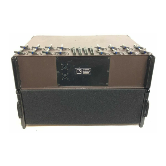
Page 26: Dv-Dosc Amplifier Racks
A channels and the B channels independently. Therefore, half an amplifier rack can power up to 3 V-DOSC (6 total), 4 SB218 or 4 dV-SUB subwoofers (8 total) or 6 dV-DOSC (12 total). In terms of construction, the amplifier rack is made of a lightweight aluminum space frame with heavy duty bracing, internal shock mounting, standard rack rails and provision for rear support of amplifiers. -
Page 27: Figure 10: Pad 04 (4 Amplifiers Per Rack)
E/F = LF AMP#2 +/- . Either DOFILL or DO2W adapters are used to convert from 8 pin CA-COM to dual Speakon connectors. Individual Speakon pinouts are : +1/-1 = dV-DOSC LF +/- ; +2/-2 = dV-DOSC HF +/- dV-DOSC dV-SUB Manual V2.0... -
Page 28: Table 1: Pad04 Amp Panel Wiring Chart
Table 1: PAD04 Amp Panel Wiring Chart dV-DOSC dV-SUB Manual V2.0 Nov 2001... -
Page 29: Figure 11: Rk12-2M And Rk12-2S Master And Slave Racks
For RK12-2M and RK12-2S, amplifier rack panel PAD02 is employed. With two LA 48 amplifiers per rack, up to 3+3 dV-DOSC can be powered whereas two LA 24 are suitable for powering up to 2+2 dV-DOSC. Just as for PADO4, PADO2 allows for connection of loudspeakers, input signal and output signal loop through. -
Page 30: Table 2: Pad02 Amp Panel Wiring Chart
Table 2: PAD02 Amp Panel Wiring Chart dV-DOSC dV-SUB Manual V2.0 Nov 2001... -
Page 31: Powering Dv-Dosc
As stated above, one L-ACOUSTICS RK12-4 rack can power up to 6 V-DOSC, 8 dV-SUB or SB218 subwoofers or 12 dV-DOSC. If both A and B sides of the rack are configured in 2-way mode and we consider the amplifiers as numbered 1 through 4 (from top to bottom as they appear in the rack) -
Page 32: Table 5: Recommended Amplifier Power Ratings For 100 Hz Lr24 Hpf
Tables 6 and 7 give a cross reference of L-ACOUSTICS LA 24 and LA 48 amplifier power ratings and MLS switch settings for powering dV-DOSC. In general terms, the LA 24 is suitable for powering up to 2 dV-DOSC while the LA 48 is recommended for powering 3 enclosures in parallel. For system protection via power matching, recommended MLS switch settings are indicated in bold italics and bold for the low and high sections, respectively. -
Page 33: Figure 13: Connecting Dv-Dosc To L-Acoustics Rk12-4
DO2W Adapter CC4FP Speakon Barrel Extension (2) Breakout at the loudspeaker end: Speakon Cable SP7 or SP25 (2) 2-WAY COMB connector V-DOSC Cable DO7 or DO25 DOFILL Adapter Figure 13: Connecting dV-DOSC to L-ACOUSTICS RK12-4 dV-DOSC dV-SUB Manual V2.0 Nov 2001... -
Page 34: Dv-Sub Enclosure Description
SB218 subwoofer cabling (as part of the V-DOSC standard) and sub cable DOSUB (8 pin CACOM to 4 x Speakon) with, or without, sub extension DO10P can be used for connecting dV-SUB to L-ACOUSTICS RK12-4 or RK12-2 amplifier racks. dV-DOSC dV-SUB Manual V2.0 Nov 2001... -
Page 35: Dv-Sub Flying System
For attachment to dV-BUMP, 4 x dV-ANGLESD should be used along with 8 x dV-PIN25. For stacking dV-DOSC directly on top of dV-SUB or when flying dV-DOSC underneath dV-SUB, 2 x dV-ANGLESD are used for attachment of the front dV-DOSC points and 2 x dV-ANGLESDP are used for attachment of the rear dV-DOSC points along with 8 dV-PIN25. - Page 36 #5 on the central spreader bar of dV-BUMP will produce a dead hang (nominal zero degrees). When flying combined dV-DOSC and dV-SUB arrays in a single column, dV-SUB is always flown on top. Under no circumstances should dV-SUB be flown beneath dV-DOSC. Maximum rated...
-
Page 37: Powering Dv-Sub
Table 10: Recommended Power and Amplifier Power Ratings for dV-SUB (EIA 1 kHz @ 1% THD) LOAD REC'D LA 48 LA 48 CROWN CROWN (ohms) POWER nominal peak MA5000 MA5002 2400 2250 2600 2250 2250 2900 dV-DOSC dV-SUB Manual V2.0 Nov 2001... -
Page 38: Dv-Dosc Control
1.9 dV-DOSC CONTROL Four digital signal processing units are currently supported and specified by L-ACOUSTICS for controlling the dV-DOSC system: XTA DP 226, DP 224 and BSS FDS 355 (Omnidrive Compact), FDS 366 (Omnidrive Compact Plus). XTA or BSS processors are supplied with proprietary presets that are intended for specific array configurations. -
Page 39: C) General Description Of Dv-Dosc Presets
For V-DOSC plus dV-DOSC presets (for example, V-DOSC+dV X LO/HI or V-DOSC + dV 4W LO/HI for XTA; VD DV X LO/HI or VD DV 4W LO/HI for BSS), dV-DOSC is preattenuated by 4 dB for downfill applications where dV-DOSC is flown underneath V-DOSC. dV-DOSC high pass filtering is set at 100 Hz and LO or HI shelving eq corresponds to the equivalent shelving eq that is applied to V-DOSC. - Page 40 Output 6 can be used for auxiliary sub drive via input B. Note: For 4W presets, the crossover frequency between the flown dV-SUB and dV-DOSC low section is 120 Hz to optimize the power bandwidth for both sections. The overall operating bandwidth for the flown dV- SUB is 30 Hz –...
-
Page 41: D) Bss Fds 355 Version 6 0801 Presets
BSS FDS 355 VERSION 6 0801 PRESETS Table 11: BSS FDS 355 Presets dV-DOSC dV-SUB Manual V2.0 Nov 2001... -
Page 42: E) Bss Fds 366 Version 6 0801 Presets
BSS FDS 366 VERSION 6 0801 PRESETS Table 12: BSS FDS 366 Presets dV-DOSC dV-SUB Manual V2.0 Nov 2001... -
Page 43: F) Xta Dp224 Version 6 0801 Presets
XTA DP224 VERSION 6 0801 PRESETS Table 13 : XTA DP224 Presets dV-DOSC dV-SUB Manual V2.0 Nov 2001... -
Page 44: G) Xta Dp226 Version 6 0801 Presets
XTA DP226 VERSION 6 0801 PRESETS Table 14: XTA DP226 Presets dV-DOSC dV-SUB Manual V2.0 Nov 2001... -
Page 45: Control Signal Distribution
A large scale system typically consists of: main Left (L) and Right (R) V-DOSC arrays and Left-Left (L- L), Right-Right (R-R) offstage fill arrays. Each of the four V-DOSC arrays can have associated 2-way dV-DOSC downfill enclosures and SB218 subwoofers therefore requiring 6 channels per array: 3 for V-DOSC, 2 for dV-DOSC and 1 for subwoofers. -
Page 46: Co 24 Control Output Panel
A, B, C, D is: Channel 1 = Sub; Channel 2 = V-DOSC Low; Channel 3 = V- DOSC Mid; Channel 4 = V-DOSC High; Channel 5 = dV-DOSC Low; Channel 6 = dV-DOSC High. Always refer to the preset description table (supplied with PCMCIA cards) to determine correct channel assignments for digital processor outputs. -
Page 47: Md 24 Multi Distro Panel
(including subwoofer amp racks which are configured using the SUB COMB connector and dV-DOSC amp racks using the 2-WAY connector as described above). A CROSS LINK cable is then used to distribute LEFT array lines from the MULTI DISTRO panel cross stage to the stage left amplifiers. -
Page 48: Cd12 Control Distro Panel
When using dV-DOSC with V-DOSC in 4-way + 2 mode, patch the V-DOSC and dV-DOSC program inputs to the Ch A and Ch B XLR inputs (use this approach if you want to run dV-DOSC off a separate matrix send using the Ch B input). Alternatively, use the parallel loop through connector to jump from the Ch A input XLR to the Channel B input on CD12 if you want to send the same input signal to V-DOSC and dV-DOSC. - Page 49 HIGH If separate sub drive is required, use the VDOSC+dV AUX presets (5-way+1). In this case, V-DOSC and dV-DOSC signal is applied to Ch A and sub drive (via a separate aux send) to Ch B. 5-WAY + 1 MODE...
-
Page 50: Figure 21: System Architecture Using Rk12-2M Master Rack And Rk12-4
Figure 21: System Architecture using RK12-2M Master Rack and RK12-4... -
Page 51: Dv-Dosc Array Specifications
According to AES recommendations, directivity is specified over an angular window with no more than 6 dB deviation. For the case of dV-DOSC, the -6dB points are at +/- 60° off axis and the horizontal directivity pattern is strictly symmetrical with respect to the 0° axis - a direct consequence of coplanar symmetry. -
Page 52: Wavefront Sculpture In The Vertical Plane
HF energy than LF. This is an important benefit of the dV-DOSC system. With distance, this tilt in tonal balance is offset by air absorption at large distances in open air situations and by both building material absorption and air absorption indoors, resulting in tonally balanced sound over the largest audience area possible. -
Page 53: Variable Curvature Dv-Dosc Array
8 dV-DOSC elements can provide a maximum vertical coverage of 8 x 7.5° = 60° while still satisfying WST criteria. The constant curvature array is the simplest type of convex curvature dV-DOSC array. This configuration should only be used for smaller sized arrays or when the geometry of the audience is unknown. -
Page 54: Cutview Sheets (Array1, Array2, Dv-Array1, Dv-Array2)
(on top of V-DOSC). Note: For dV-DOSC, site angles are not referenced to the trapezoidal enclosure wall – they are referenced to a line that is perpendicular to the front of the enclosure at the middle of the enclosure. This is because dV-DOSC radiates a flat wavefront that is parallel to the front of the enclosure. -
Page 55: Figure 23: Parameters For The Room Dim Utility Sheet In Array
Note that the displayed top element corresponds to the BUMPER, not the first element of the dV-DOSC array. XZ cells can be used to enter additional room features such as balcony profiles, stage/proscenium details, FOH mix position, etc. -
Page 56: B) Optimization Procedure
Note: The site angle for dV-DOSC element #1 is equal to the dV-BUMP site angle provided that a 3.75° angle bar is used at the rear to connect element #1 to the bumper. If a 3.75° angle bar is used, a laser and/or remote digital inclinometer can be mounted on the dV-BUMP to measure the focus of the top element. -
Page 57: Figure 25: Physical Dv-Dosc Rigging Parameters For Array
(scaffold bay, clearance to proscenium wall etc). Please see Figure 25 for further details. Figure 25: Physical dV-DOSC Rigging Parameters for ARRAY ACOUSTICAL PREDICTION data gives the continuous unweighted SPL of the array referenced to 1 m and the unweighted SPL of the array at a selected distance (enter the distance in the black cell). -
Page 58: Simulating Dv-Dosc Downfill
DOSC array. Offset distance, elevation and site angle values are also provided for applications where dV-DOSC is used with V-DOSC for downfill or upfill. When a V-DOSC array is defined in the ARRAY1sheet, dV-DOSC downfill or upfill simulation parameters are automatically calculated in the dV-ARRAY1 and dV-ARRAY2 sheets. -
Page 59: Dv-Dosc Pick Point Utility
This corresponds to the SPL that would be obtained along the isocontour of each array. The Console Output Signal can be increased to up to 11dBu for dV-DOSC, 17 dBu for V-DOSC - at this point the amount of headroom available in the system goes to zero and the user has an indication as to the peak A-weighted SPL that will be available along the isocontour. -
Page 60: B) Optimization Procedure
The overlap between L, R arrays also gives an indication as to which portions of the audience will experience stereo imaging. dV-DOSC dV-SUB Manual V2.0 Nov 2001... -
Page 61: Array 2000 Spreadsheet Calculation Examples
ARRAY 2000 SPREADSHEET CALCULATION EXAMPLES CUTVIEW SHEET HORIZONTAL ISOCONTOUR SHEET Figure 26a: ARRAY 2000 spreadsheet calculation example (LCR dV-DOSC system) dV-DOSC dV-SUB Manual V2.0 Nov 2001... -
Page 62: Figure 26B: Simulating Dv-Dosc Under V-Dosc
Figure 26b: Simulating dV-DOSC under V-DOSC Figure 26c: Simulating dV-DOSC on top of V-DOSC dV-DOSC dV-SUB Manual V2.0 Nov 2001... -
Page 63: Elements Of Sound Design
When the horizontal coverage of a dV-DOSC array (120° nominal, 100° effective) is not sufficient, the solution is not to place a second array directly beside the first one. The correct approach is to utilize a second array which is focused on another portion of the audience and spaced at least 6-7 meters (approximately 20 ft) away from the first array. -
Page 64: Stacked Or Flown
The stacking system is rated for a maximum of 12 dV-DOSC elements. For this type of installation, the precise nature of dV-DOSC vertical coverage allows little margin for error. The designer must know if the audience is standing or seated - the bottom of the array should always be higher than the ears of the first rows of the audience and the lowest element tilted downwards. -
Page 65: Flying Guidelines
Flying Guidelines For single point hangs, the flying system is rated for a maximum of 24 dV-DOSC elements without the extension bar and 12 dV-DOSC elements with the extension bar. Particular attention must be paid to the height at which the array is flown when predicting the vertical coverage in ARRAY 2000 (Cutview). -
Page 66: Subwoofers
7,500 m volume. Note: In terms of simple component count, 3 V-DOSC is the equivalent of 6 dV-DOSC and 2 dV-SUBs (6x15’’, 12xMF, 6xHF). Therefore, the standard ratio of 3:1 dV-DOSC:dV-SUB will provide the equivalent of V-DOSC standalone as a 3-way enclosure in terms of overall tonal balance and low frequency impact. For increased low frequency impact, additional subwoofers are required just as for V-DOSC. -
Page 67: Flown Subwoofers
♦ Cleaner staging and better sightlines. NOTE: When subwoofers are flown and closely coupled to the dV-DOSC array, presets for use with the SB218 are dV 3W SB218 L0/HI (XTA) and DV 3W SB L/H (BSS). Presets for use with dV-SUB are dV 3W 120 dVS LO/HI or dV 3W 200 dVS LO/HI (XTA) and DV 3W 120 L/H or DV 3W 200 L/H (BSS). -
Page 68: Central Location, Ground Stacked
8'' components. This is the case for 3W presets while for 3WX presets, the dV-DOSC low section is high pass filtered at 80 Hz and the limiter is set at 5 dBu. For 3WX presets, since there is no overlap in the effective operating bandwidths of sub and dV- DOSC low sections, the subwoofers can be operated with the same polarity in 3-way mode without phase problems due to the overlap of crossover frequencies. - Page 69 200 Hz crossover points, λ/2 is: 2.15 m, 1.4 m, 0.86 m, respectively. Therefore, all crossover points will satisfy WST Criterion #2 for the case of single, closely coupled arrays of dV-DOSC and dV-SUB. For flown coplanar systems, the spacing between acoustic centers of the 2 dV-SUB arrays becomes 1.92 metres, therefore the 200 Hz crossover preset should not be used.
-
Page 70: 4-Way Presets For Dv-Dosc And Dv-Sub Or Sb218 Subwoofers
BSS are named: DV 4W DVS L/H and DV 4W SB L/H. Note: For 4W presets, the crossover frequency between the flown dV-SUB and dV-DOSC low section is 120 Hz to optimize the power bandwidth for both sections. The overall operating bandwidth for the flown dV- SUB is 30 Hz –... -
Page 71: Installation Procedures
Verify the tilt angle for the first element and perform any required tilt adjustments using the rear screwjacks. Note : Compensate for the 3.75 degree trapezoidal angle of dV-DOSC versus the actual site angle by using a 3.75 degree angle between the rear of the bottom enclosure and dV-BUMP. -
Page 72: Safety Rules
(even when attaching to the dV-BUMP). Place the second dV-DOSC on top of the bottom enclosure by mating the two front rigging posts on the second element and the dV-ANGLE bars that were previously mounted on the bottom element with the available locator slots. - Page 73 (i) Place V-DOSC BUMP into position (ii) dV-BUMP locator studs mate with holes on V-DOSC BUMP (iv) Insert locator pin (iii) dV-BUMP mounted inside V-DOSC BUMP dV-DOSC dV-SUB Manual V2.0 Nov 2001...
- Page 74 (vi) Overview of dV-BUMP secured to V-DOSC BUMP (v) Use dV-PIN81 to secure locator pin (vii) Attach rear screwjacks to V-DOSC BUMP (viii) Select 3.75 deg (middle hole) for rear points on dV-BUMP dV-DOSC dV-SUB Manual V2.0 Nov 2001...
- Page 75 (x) Front rigging tabs mate with locator slots on dV-BUMP (xii) Then pin the rear points - note: by pre-selecting the angle, the tab on dV-ANGLEP1 acts as a stop when dV-DOSC is placed in position (xi) Pin front points first using dV-PIN25 dV-DOSC dV-SUB Manual V2.0...
- Page 76 (xiii) Pre-attach two more dV-ANGLE bars at desired angle (xiv) Stack the second dV-DOSC enclosure (xv) Pin front points first, rear points last using dV-PIN25 (xvi) Use dV-ANGLE at 3.75 (rear) and 7.5 (front) degree positions as a site for adjusting the focus of the stacked system dV-DOSC dV-SUB Manual V2.0...
-
Page 77: Stacking On Top Of V-Dosc
Stacking on top of V-DOSC To fly dV-DOSC on top of V-DOSC, dV-BUMP is attached to the V-DOSC bumper to act as a stacking platform as in the standalone stacking procedures outlined above. For stability reasons, the maximum number of dV-DOSC elements that can be stacked on top of V- DOSC is 6. - Page 78 (ii) Raise and level the V-DOSC BUMPER (i) dV-BUMP and V-DOSC BUMPER (iii) Place dV-BUMP inside V-DOSC BUMPER (iv) Attach locator pin into position using dV-PIN81 dV-DOSC dV-SUB Manual V2.0 Nov 2001...
- Page 79 (v) Attach rear dV-ANGLE and mount the first element (vi) Continue to build the stack (vii) Note bridling arrangement in front (viii) Entire system is now ready to fly dV-DOSC dV-SUB Manual V2.0 Nov 2001...
-
Page 80: Stacking On Top Of Sb218 Subwoofers
Start by building a stack of SB218 subwoofers. From ground level, stacking at least four SB218 enclosures high puts dV-DOSC at a good height so that the bottom cabinet will be angled down into the audience. Before stacking dV-DOSC, secure SB218 cabinets together using V-DOSC ANGLE straps between cabinets (and/or a ratchet strap running around the entire stack). - Page 81 (i) Note circular discs on dV-BUMP (ii) These mate with stacking runner recesses on SB218 (iv) Double stud to ring fitting attached to SB218 flytrack (alternative: (iii) dV-BUMP placed into position run a ratchet around the entire stack) dV-DOSC dV-SUB Manual V2.0 Nov 2001...
- Page 82 (v) Ratchet strap secures dV-BUMP to the SB218 (vi) Rear dV-ANGLE pre-attached at desired angle (viii) Pre-attach next set of dV-ANGLE (vii) Bottom dV-DOSC mounted, attached using dV-PIN25 dV-DOSC dV-SUB Manual V2.0 Nov 2001...
- Page 83 (x) then secured using dV-PIN25 (front first then rear) (ix) Second dV-DOSC placed into position (xii) for more downwards tilt (xi) Use dV-ANGLE N instead of dV-ANGLE P1… dV-DOSC dV-SUB Manual V2.0 Nov 2001...
-
Page 84: Stacking Dv-Sub Subwoofers
1) use a ratchet strap around the entire stack or 2) use dV- ANGLESS (sub-to-sub) angle bars between adjacent dV-SUB enclosures. Either of these options is recommended, especially if dV-SUB will serve as a stacking platform for dV-DOSC (see the following section). - Page 85 Rotate/lower the second dV-SUB into position and position all four dV- Use 4 x dVPIN25 to attach the second enclosure to the bottom dV-SUB ANGLESS in the corresponding slots of the bottom enclosure's rigging panels dV-DOSC dV-SUB Manual V2.0 Nov 2001...
- Page 86 The stack - secured using 8 dV-ANGLESS and 16 dVPIN25 Repeat the same procedure to stack 3 dV-SUBs high dV-DOSC dV-SUB Manual V2.0 Nov 2001...
-
Page 87: Stacking Dv-Dosc On Top Of Dv-Subs
When stacking on stages or risers, reduced downwards tilt requirements for the stacked dV-DOSC system may allow for the direct installation of dV-DOSC on top of dV-SUB without use of dV-BUMP. Two dV-ANGLESD (sub to dV-DOSC) angles are used for the front attachment points and two dV- ANGLESDP (sub to dV, positive tilt) are used for the rear attachment points of the first dV-DOSC. - Page 88 (i) Pre-attach dV-ANGLESD (front) and dV-ANGLESDP (rear) to dV-SUB towards the center of dV-SUB on both sides (iv) Lift dV-DOSC into position and secure with dV-PIN25 (iii) Place dV-DOSC in position (inverted) and secure the front 2 points dV-DOSC dV-SUB Manual V2.0 Nov 2001...
- Page 89 (v) Pre-select the angle / pre-attach dV-ANGLE P1 or P2 for the second dV- (vi) The finished stack of dV-SUB and dV-DOSC DOSC elements and continue to build the stack dV-DOSC dV-SUB Manual V2.0 Nov 2001...
-
Page 90: Procedure 2: Stacking With Dv-Bump
3 dV- SUB enclosures high puts dV-DOSC at a good height so that the bottom cabinet will be angled down into the audience. Typically downwards tilt is necessary to reduce audience shadowing effects and to improve HF penetration into the audience. - Page 91 (iii) 3 high dV-SUB stack provides a good height as a stacking platform. With the bottom element tilted downwards, coverage starts from 2 metres onwards. (ii) dV-DOSC installed - note how dV-ANGLEN provides downwards tilt dV-DOSC dV-SUB Manual V2.0 Nov 2001...
-
Page 92: Flown Systems
Line up all dV-DOSC enclosures in their flight cases (3 per case). Mate the bottom rigging tabs from the first group of 3 cabinets with the top locator slots of the next group of cabinets. Repeat until all dV-DOSC flight cases are physically lined up. - Page 93 Referring to the angle values that were pre-calculated for each element using ARRAY 2000, pre- attach pairs of dV-ANGLE bars at the rear of all dV-DOSC elements of the array (while they are still face down in their flight cases). Remember to keep the ball/tab end up and oriented towards the dV- BUMP as a reference.
- Page 94 (ii) Pin the fronts of all dV-DOSC using dV-PIN25 (iii) Use 3.75 degree for rear when attaching dV-BUMP (i) dV-DOSC lined up in FLIGHT-dV cases dV-DOSC dV-SUB Manual V2.0 Nov 2001...
- Page 95 (iv) Pre-attach all rear dV-ANGLE (ball end up) (v) Pre-select the desired angle (vii) Connect dV-DOSC enclosures in groups of three (vi) dV-BUMP attached, dV-ANGLE pre-attached dV-DOSC dV-SUB Manual V2.0 Nov 2001...
- Page 96 (viii) Lower detail between adjacent blocks of 3 dV-DOSC (ix) As cabinets lift off … (x) Pin adjacent blocks of 3 together as the gaps close dV-DOSC dV-SUB Manual V2.0 Nov 2001...
- Page 97 (xi) Note: single point hang from spreader bar section on dV-BUMP (xii) Front view of the flown array dV-DOSC dV-SUB Manual V2.0 Nov 2001...
- Page 98 (xiv) 90 degrees vertical coverage running from parallel to vertical (xiii) Single point hang from rear point on extension bar gives 90 degrees with respect to floor level coverage with 12 dV-DOSC dV-DOSC dV-SUB Manual V2.0 Nov 2001...
-
Page 99: Trim And Angle Adjustments
Note: For dV-DOSC, do not use the top and bottom of the cabinet as a visual reference (as for V-DOSC). The radiated wavefront is parallel to the front of the cabinet and is not defined by the trapezoidal enclosure walls. - Page 100 Verifying coverage down front is more difficult since the trapezoidal angle of dV-DOSC cannot be used as a reference. If you can see the bottom of the bottom dV-DOSC you are definitely outside the coverage pattern (more so than for V-DOSC). Attaching an extra dV-ANGLE at the rear of the bottom cabinet at 3.75 degrees and using this as a site reference with the front rigging post can help...
-
Page 101: Flying Under V-Dosc With Dv-Down
Connect the rears of all 3 dV-DOSC elements while they are still face down in their flight cases by pulling the cabinets together at the rear and inserting dV-PIN25. This operation is facilitated by the fact that all fronts are pinned together and can pivot, plus all rear angles were pre-attached in the previous step. - Page 102 (i) Pre-attach dV-DOWN on either side of dV-DOSC (ii) Use dV-PIN25 to connect front points of all dV-DOSC (iii) Rotating leg on bottom V-DOSC flipped down, ANGLE strap (iv) Align rotating leg with holes on dV-DOWN not attached on bottom element dV-DOSC dV-SUB Manual V2.0...
- Page 103 (v) Attach dV-DOWN using U-PIN and locking safety (vi) Preconnect all dV-ANGLE at the rear of dV-DOSC (viii) Connect ANGLE straps on bottom V-DOSC (vii) Pin all dV-DOSC at the rear using dV-PIN25 dV-DOSC dV-SUB Manual V2.0 Nov 2001...
- Page 104 (ix) Raise the ARRAY - note the gap (x) Tighten screwjacks to remove this gap (xi) dV-DOSC flown under V-DOSC dV-DOSC dV-SUB Manual V2.0 Nov 2001...
-
Page 105: Flying Dv-Sub Standalone
Flying dV-SUB Standalone When flying dV-SUB standalone, up to 6 dV-SUBs deep can be flown from dV-BUMP (single or two point hang). Please refer to the photo sequence below in addition to the following description of dV- SUB rigging procedures. To fly the system, the first dV-SUB enclosure is located at the rigging location and flipped onto it's stacking runners in the normal orientation. - Page 106 (i) dV-ANGLESD pre-attached - note that the stacked hole position has been (ii) dV-BUMP placed into position and secured using 4 x dV-ANGLESD and 8 x selected and the ''fat'' part of the angle bar is oriented towards the center dV-PIN25 (iii) Float the first enclosure, pre-attach 4 x dV-ANGLESS, land on the second (iv) Pick point hole #5 (from the front) on the central spreader bar section of...
- Page 107 Lower 1 dV-SUB into position and attach using 4 dV-PIN25 dV-DOSC dV-SUB Manual V2.0 Nov 2001...
-
Page 108: Flying Dv-Dosc Under Dv-Sub (3+1 Configuration)
Referring to the angle values that were pre-calculated for each element using ARRAY 2000, pre- attach pairs of dV-ANGLE bars at the rear of all dV-DOSC elements of the array (while they are still face down in their flight cases). Remember to keep the ball / tab end up as a reference and be careful to select the correct angle for each element (generally, it is better if one person performs this operation to avoid mistakes). - Page 109 Pre-connect the rear point only for the first dV-DOSC to the dV-SUB, i.e., use 2 x dV-PIN25 to secure dV-DOSC to the dV-ANGLESDP that was pre-attached at the (bottom) rear of dV-SUB Note : Selecting the 0 degree angle on dV-ANGLESDP (between the rear of the top dV-DOSC enclosure and dV-SUB) is necessary to compensate for the 3.75 degree trapezoidal angle of dV-DOSC versus the actual...
- Page 110 (i) dV-ANGLESDP pre-attached to the rear of dV-SUB (ii) dV-ANGLESD pre-attached to the front of dV-SUB (iv) dV-DOSC located behind the array (iii) dV-BUMP attached to dV-SUB using 4 x dV-ANGLESD and 8 x dV-PIN25...
- Page 111 (vi) Houston - we have liftoff… (v) Attach rear points only (dV-SUB to dV-DOSC) (vii) Lift dV-DOSC into position, secure front points using 2 x dV-PIN25 (viii) The flown array dV-DOSC dV-SUB Manual V2.0 Nov 2001...
-
Page 112: Flying Dv-Dosc Under Dv-Sub (Larger Configurations)
Pre-connect the front and rear points for the first dV-DOSC to the dV-SUB, using 4 x dV-PIN25. Do not connect the rear of dV-DOSC #2 to #1 (this will be done as the system is flown). Do connect the rear of dV-DOSC #2 to #3. -
Page 113: Procedure 2 (Larger Configurations)
Connect the front and rear motors (or single motor) to dV-BUMP. Slowly begin to raise the array. As the array lifts off, the rear gaps between dV-DOSC #1 to #2 and then between blocks of 3 cabinets will automatically close, allowing you to progressively pin the blocks together as system goes up. - Page 114 PROCEDURE 1 (ii) Second dV-SUB with 4 x dV-ANGLESS pre-attached (i) dV-SUB with dV-BUMP attached using 4 x dV-ANGLESD and 8 dV-PIN25 (iii) 2 x dV-SUB physically connected (iV) dV-ANGLESD (front) and dV-ANGLESDP (rear) pre-attached...
- Page 115 (Do not attach the dV-DOSC #2 to dV-DOSC #1) (viii) The flown system (2 dV-SUB + 6 dV-DOSC) (vii) dV-DOSC #2 to #1 then blocks of 3 are attached as the array is raised dV-DOSC dV-SUB Manual V2.0 Nov 2001...
- Page 116 PROCEDURE 2 (i) dV-DOSC are pre-attached in blocks of 3 (ii) Flip dV-DOSC onto dV-SUB dolleys to position under the dV-SUB array (iv) dV-DOSC front point attachment using dV-ANGLESD. The array is then (iii) Standalone dV-SUB techniques (see above) are used to fly the dV-SUB array raised and the rear points attached using dV-ANGLESDP dV-DOSC dV-SUB Manual V2.0...
- Page 117 PROCEDURE 2 (v) The procedure is repeated with subsequent blocks of 3 dV-DOSC dV-DOSC dV-SUB Manual V2.0 Nov 2001...
-
Page 118: Safety Rules
- 14 V-DOSC + 6 dV-DOSC maximum GROUND STACKED dV-DOSC (STANDALONE) - 12 maximum using dV-BUMP + V-DOSC BUMPER provided that the dV-DOSC array is physically contained within the vertical footprint of the V-DOSC BUMPER. dV-DOSC STACKED ON TOP OF V-DOSC... - Page 119 • flown and determine chain motor ratings accordingly. • When dV-DOSC is flown on top of, or below V-DOSC account for the additional weight and adjust your chain motor ratings accordingly. • Always be sure that the immediate area is clear of people and obstacles whenever raising or lowering the array.
-
Page 120: Maintenance And Installation Tools
4 mm hex key DOSC Waveguide Mount Bolt 10 mm socket Miscellaneous Tools : adjustable pliers, rubber mallet, sidecutters, wire stripper, soldering iron, digital voltmeter (DVM), breakout cables for speaker testing (CA COM to banana leads). dV-DOSC dV-SUB Manual V2.0 Nov 2001... -
Page 121: Spare Parts
Rear angle bar (0, -2, -3.75, -5.5, -7.5 degrees) dV-ANGLEN dV-SUB to dV-SUB angle bar dV-ANGLESS dV-SUB to dV-DOSC angle bar dV-ANGLESD dV-SUB to dV-DOSC angle bar (0, 1.75, 3.75 deg) dV-ANGLESDP Equipped flying bumper dV-BUMP dV-BUMP shackle (18 mm) CA-MAN 18... -
Page 122: Recommended Installation Tools
Real Time Analyzer - DBX or Sound Technology RTA-1 Polarity Checker - PC 80 MK 11 SCV Audio, BSS (or equivalent) Laser Level Device 2x 20 m (50 ft) tape measures Figure 27: Recommended Installation Tools dV-DOSC dV-SUB Manual V2.0 Nov 2001... -
Page 123: Specifications
6. SPECIFICATIONS 6.1 DV-DOSC ELEMENT SPECIFICATIONS L-ACOUSTICS specifications are based on measurement procedures which produce unbiased results and allow for realistic performance prediction and simulation. Some of these specifications will appear conservative when compared with other manufacturer's specifications. Measurements are conducted under free field conditions and scaled to a 1 m reference distance unless otherwise specified. -
Page 124: Figure 28: Dv-Dosc Element - Line Drawing
Figure 28: dV-DOSC Element – Line Drawing dV-DOSC dV-SUB Manual V2.0 Nov 2001... -
Page 125: Table 17: Dv-Dosc Weight Per Number Of Cabinets
Table 17: dV-DOSC weight per number of cabinets Number of Cabinet Cabinet dV-DOSC Weight Weight Cabinets (kg) (lbs) 63.6 140.2 95.4 210.3 127.2 280.4 159.0 350.5 190.8 420.6 222.6 490.7 254.4 560.9 286.2 631.0 318.0 701.1 349.8 771.2 381.6 841.3 413.4 911.4... -
Page 126: Dv-Sub Specifications
1x 4 pin Neutrik Speakon (1+/1-) Material 24 mm Baltic birch plywood (sealed, screwed and rabbeted angles, internally braced) Finish Maroon-gray™ Grill Black epoxy-coated perforated steel, acoustically transparent foam Rigging Integral flying hardware and handles dV-DOSC dV-SUB Manual V2.0 Nov 2001... - Page 127 Figure 29: dV-SUB Line Drawing dV-DOSC dV-SUB Manual V2.0 Nov 2001...
-
Page 128: Figure 30: Front View Of Dv-Dosc Array And Vertically Stacked Dosc Waveguides
WST criteria is satisfied over the majority of the 8" operating bandwidth. Figure 30: Front view of dV-DOSC array and vertically stacked DOSC waveguides We have to fulfil the first WST criterion at higher frequencies since it is not possible to satisfy the second WST criterion, i.e., the wavelengths are too small to have the acoustic centers of adjacent... -
Page 129: Appendix 1: How Does Dv-Dosc Behave With Respect To Wst Criteria
λ/4 at the highest operating frequency - this corresponds to less than 5 mm of curvature at 16 kHz and experiments have shown that the DOSC waveguide provides less than 4 mm of curvature. DOSC waveguide technology is patented on an international basis. (n°0331566 in Europe, n°5163167 in North America). dV-DOSC dV-SUB Manual V2.0 Nov 2001...
Need help?
Do you have a question about the dV-DOSC and is the answer not in the manual?
Questions and answers