Advertisement
Quick Links
Advertisement

Related Manuals for Resource Tango 223


Summary of Contents for Resource Tango 223
- Page 1 Assembly Instructions Tango 223 / 270...
- Page 2 Warranties for all products purchased from Resource Furniture, LLC are only valid if the product has been properly assembled, Installed by a trained professional, and operated in accordance with the assembly instructions. Resource Furniture accepts no responsibility for any damage or injury caused by Improper Installation.
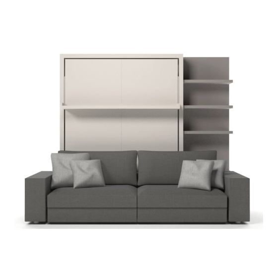
- Page 3 TANGO OVERVIEW Tango 223 Tango 270 TANGO MATTRESS SPECIFICATIONS Recommended weight: ~ 64 lbs Recommended dimensions: 79 1/2 x 60 x 7”...
- Page 4 TANGO OVERVIEW FIXED SEAT MODEL...
- Page 5 TANGO OVERVIEW SLIDING/CHAISE SEAT MODEL...
- Page 6 UPPER BOISERIE SHELVES Boiserie Panel Bottom Boiserie Shelves Boiserie Box (12 3/4”Depth) A proper wall anchor suitable for the wall’s construction must be selected by the contractor or installer.
- Page 7 TANGO COMPONENTS CODE QTY. COMPONENTS Right side panel Left side panel Top horizontal panel Base Left/right small side panels (already attached to 1 & 2) Right back panel Left back panel Bed frame Mattress support bar Shelf Boiserie panel (optional) Left arm bracket Right arm bracket Sofa base...
- Page 8 TANGO FIXED SEAT STRUCTURAL HARDWARE CODE QTY. COMPONENT DESCRIPTION 7 x 36 6MA Pins D15 L17 Cam Connectors Wood screws for back 3.5 x 20 panels 5MA x 50 Screws for side panels Screws for mattress support 4MA x 18 4 x 40 Screws to attach top panel 8MA x 25...
- Page 9 TANGO SLIDING SEAT STRUCTURAL HARDWARE CODE QTY. COMPONENT DESCRIPTION 7 x 36 6MA Pins D15 L17 Cam Connectors Wood screws for back 3.5 x 20 panels 5MA x 50 Screws for side panels Screws for mattress support 4MA x 18 4 x 40 Screws to attach top panel 8MA x 25...
- Page 10 TANGO TOOLS QTY. DESCRIPTION Allen wrench 3 MM Allen wrench 4 MM Allen wrench 5 MM Allen wrench 8 MM BOISERIE PANEL TOOLS QTY. DESCRIPTION Metal shelf pins Boilts for shelf pins Boiserie bar Wall anchors Note: The installer must determine the composition of the wall and appropriate anchors prior to installation.
- Page 11 STRUCTURE ASSEMBLY Attach the (2) left side panel to the (4) base using 2 (D) screws. These pieces are pre-assembled. Attach the 7 left back panel to the 2 left side panel using 3 A pins and 3 B cam connectors. Attach the 6 right back panel to the 7 left back panel with 3 A pins and 3 B cam connectors.
- Page 12 STRUCTURE ASSEMBLY Attach the (3) top horizontal panel to the (2) left side panel with 2 (A) pins and 2 (B) cam connectors, and to the back panels with 4 (F) screws. Attach the 1 right side panel to the 4 base using 2 D screws, and to the top horizontal panel and back panels with 5 A pins and 5 B cam connectors.
- Page 13 OPTIONAL WAND LIGHTING Drill 1/2” hole at 21 3/8” measured downward from the inside of the top of structure and 1 1/2” in from the left and or right vertical side panel (on the inside). Install mounting plate with provided wood screws. Wand Light Exploded Diagram Cord Length = 118”...
- Page 14 LEVELING THE STRUCTURE Ensure that the structure is level and plumb. To compensate for any floor unevenness, use the adjustable feet on the bottom panel (det. 1 4a) to level the structure. det.1...
- Page 15 BED FRAME INSTALLATION Unscrew the safety plates fixed to the (4) structure base, as shown in det. 5a. det.5a Position the (8) bed frame within the structure as shown. Place the levers located near the head of the bed frame into their slots as shown in det. 6a, and re-attach the safety plates from Image 5.
- Page 16 BED FRAME INSTALLATION Attach the (9) mattress support bar to the bed frame using six (E) screws. Lift the 8 bed frame into its upright vertical position. Screw the base pin to the lever cords, leaving the screw on the outer side. Pass the cord under the pulleys on the base 4 and secure the pins on the appropriate seat.
- Page 17 FRONT SHELF INSTALLATION Attach the shelf to the feet of the bedframe, as shown, using 4 (I) screws. Installing the shelf IMG.9: Attach the shelf to the feet of the bedframe, as shown, using 4 (I) screws. BED OPERATION OPENING THE BED IMAGE 10: Grasp the handle in the center of the shelf and pull down the bed, gently accompanying the Grasp the handle in the center of the shelf and pull down the bed, gently accompanying...
- Page 18 BED AND HEADBOARD INSTALLATION Attach the headboard (if purchased by client) to the back of the structure. Secure the mattress to the bedframe by fastening the two buckled straps.
- Page 19 BED FRAME ADJUSTMENT To balance the bedframe, adjust the spring tension controllers with the 8mm allen wrench provided. Turn clockwise to adjust the tension in order to close the bed with ease. ensuring that each side of the bedframe is adjusted equally. Note: An excessive number of turns may damage the cable.
- Page 20 BOISERIE PANEL ASSEMBLY Insert and fasten the (M) metal shelf pins into the holes on the (11A) boiserie panel using 2 (N) bolts each. Place the boiserie panel next to the bed and Slide the boiserie shelves (11B) over ensure panel is level and plumb. Attach the (O) the (M) metal shelf pins.
- Page 21 BOISERIE PANEL ASSEMBLY Insert and fasten the (M) bottom metal shelf pins into the holes on the (11A) boiserie panel. Slide the bottom boiserie shelves over the pins. Align the (11C) storage box with the lower part of the boiserie panel.
- Page 22 SOFA INSTALLATION Bring the (14) sofa hardware towards the base, as shown. Sliding Sofa Seat Option: Position the metal frame with wheels facing towards the back of the bed. (det.21a). Fixed Sofa Seat Option: Position the metal frame with rubber stops facing forward (det. 21b).
- Page 23 SOFA INSTALLATION Attach both the (12) left and (13) right metal arm brackets to the (4) base using 2 (H) screws, 2 (J) nuts, and 2 K washers, as shown in det. 22a. Attach both the (12) left and (13) right metal arm brackets to the (14) fixed/sliding sofa base with 2 (H) screws, as shown in det.
- Page 24 SOFA INSTALLATION The Tango 270 features a sofa component that will extend past the width of the structure to one side, as previously determined by the client. In the example below, the sofa extends to the right of the structure. Attach the 12 left metal arm bracket to the 4 base using 2 H screws, 2 J nuts, and 2 K washers, and to the 14 fixed/sliding sofa base with 2 H screws.
- Page 25 PADDED BACK BAR INSTALLATION Position the (20) padded back bar to align with the predrilled holes on the (12) left and (13) right arm brackets, and secure using 4 (G) screws, as shown in det. 25a.
- Page 26 PADDED BACK BAR INSTALLATION Flip up the padded back bar. The arm brackets have a mechanism that will lock the bar in place at various points; you must fully flip the bar down to unlock the mechanism in order to bring the bar back to its ‘up’...
- Page 27 FIXED SEAT INSTALLATION Position the (16) right and (17) left sofa seats to align with the predrilled holes at the front of the sofa base, as shown. Left/right labels are at the bottom of each seat. Attach the 16 right and 17 left sofa seats to the sofa base through the predrilled holes in each seat using 4 L screws (detail 28a).
- Page 28 SLIDING SEAT INSTALLATION Position the (16) right and (17) left sofa seats in the sofa base, as shown. Left/right labels are at the bottom of each seat. The side of the seat that slopes downwards should be closest to the structure. The sliding sofa seat can be extended out to a maximum of 200mm (7.9inches).
- Page 29 ARMRESTS INSTALLATION Secure the (18) left and/or (19) right armrests to the (12) left and/or (13)a right metal arm brackets by sliding the armrests into the metal tapers. The armrests are labeled left/right. The Tango Sofa system is modular and can feature a number of seats that can extend to the left or right of the main sofa structure.
- Page 30 MODULAR SEATS INSTALLATION The rest of the (optional) modular seats are attached to each other using a fork and pin system (illustrated in det. 33a) that holds the entire system together and locks with a click. To disassemble, lift the piece equipped with the triangular pin about 1inch to clear the fork.
-
Page 31: Configuration Examples
CONFIGURATION EXAMPLES TANGO 270... - Page 32 CONFIGURATION EXAMPLES TANGO 270...
- Page 33 SAFELY OPERATING YOUR To Open The TANGO BED Bed: Remove the sofa cushions. Flip down the back bar that supports the sofa cushions. Remove the sofa cushions. Flip down the back bar that supports the sofa cushions Grasp the handle located in the middle of the shelf and pull with one hand, while supporting the top of the bed frame with Grasp the handle located on either side of...
- Page 34 To Close Your Bed: SAFELY OPERATING YOUR TANGO BED Remove bed pillows and tuck bedding in on all Stand in the middle of the bed, grasp fron sides around and under the mattress of the bed frame and lift. Latch both mattress straps over the bedding. Continue to lift the bed frame as you walk f Remove pillows and tuck bedding in on all sides around mattress.
- Page 35 ResourceFurniture.com...
Need help?
Do you have a question about the Tango 223 and is the answer not in the manual?
Questions and answers