Advertisement
Quick Links
Advertisement

Related Manuals for Resource Kali Board 90


Summary of Contents for Resource Kali Board 90
- Page 1 Assembly Instructions Kali Board 90/120...
- Page 2 Warranties for all products purchased from Resource Furniture, LLC are only valid if the product has been properly assembled, Installed by a trained professional, and operated in accordance with the assembly instructions. Resource Furniture accepts no responsibility for any damage or injury caused by Improper Installation.
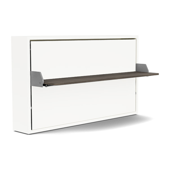
- Page 3 KALI BOARD 90/120 OVERVIEW Kali 90 Board Kali 120 Board KALI BOARD 90 MATTRESS SPECIFICATIONS KALI BOARD 120 MATTRESS SPECIFICATIONS Recommended weight: ~ 36 lbs Recommended weight: ~ 50 lbs Recommended dimensions: 31 1/2” x 78” x 7” Recommended dimensions: 41” x 78” x 7”...
- Page 4 KALI BOARD 90/120 OVERVIEW...
- Page 5 KALI BOARD 90/120 OVERVIEW...
- Page 6 KALI BOARD 90/120 COMPONENTS CODE QTY. COMPONENTS Right side panel Left side panel Top horizontal panel Bottom horizontal panel Bed frame Back panels Headboard Metal mattress support bar Desk brackets Desk KALI BOARD 90/120 WALL MOUNTING HARDWARE CODE QTY. DESCRIPTION...
- Page 7 KALI BOARD 90/120 STRUCTURAL HARDWARE CODE QTY. DESCRIPTION Pins Cam connectors Phillips screw Hex screws - for attaching bed frame to structure Flanged screws - for attaching desk to desk mechanism Conical Washers - for attaching desk mechanism to side panels...
- Page 8 STRUCTURE ASSEMBLY Screw 8 (A) connector bolts into the (1) right vertical and (2) left vertical panels. Attach the (3) horizontal top and (4) horizontal bottom panels to the veritcal panels by inserting and tightening 8 (B) cams. Attach the (6) back panel to the structure with 22 (C) Phillips screws.
- Page 9 OPTIONAL KALI 90 WAND LIGHTING Drill 1/2” hole at 37 7/8” measured from the bottom of the structure (from inside) and 1 1/2” in from the side. Install mounting Plate with provided wood screws, aligning the 1/2” drill holes. Wand Light Exploded Diagram Cord Length = 118”...
- Page 10 Wand Lighting OPTIONAL KALI 120 WAND LIGHTING Kali 120 Installation Guideline for • Drill 1/2” hole at 37 7/8” measured from the bottom of the structure (from inside) and 1 Drill 1/2” hole at 37 7/8” measured from the bottom of the structure (from inside) and 1 1/2” in 1/2”...
- Page 11 LEVELING THE STRUCTURE Ensure that the structure is level and plumb. To compensate for any floor unevenness, use the adjustable feet on the (4) horizontal bottom panel (det. 2a) to level the structure. det.2a...
- Page 12 WALL BED ATTACHMENT Locate the two open spaces at the top of the 6 back panel. Draw a line through the open space along the top 3 panel as shown in Image 3 to mark where the wall anchors will be placed. Move the structure away from the wall and attach the WB wall bracket to the wall using 2 WA wall anchors.
- Page 13 WALL BED ATTACHMENT Re-position the structure against the wall, ensuring that the 2 wall brackets pass through the open spaces in the back panel. Attach the bracket to the bottom of the top horizontal panel by screwing 1 (WA) screw into each bracket as shown. Do not fasten completely. Adjust the position of the structure, ensuring that it is level and plumb.
- Page 14 BED BASE INSTALLATION Fasten the 8 mattress support bar to the 5 bed frame using the 5MA x 20 screws attached to the bar. Mattress bar must be installed before the bed base is inserted into the structure. det.7a...
- Page 15 BED BASE INSTALLATION Position and insert the (5) bed frame within the structure as shown in det. 8a. det.8a det.8a...
- Page 16 BED BASE INSTALLATION Close the lower bed and fasten 2 (D) hex screws into the mechanisms on both vertical panels, as shown in det. 9a.
- Page 17 DESK INSTALLATION Open the bed by pressing down on one of the two locking levers located on the sides of the bed frame. Position the (9) desk brackets so that they face towards the structure, as shown below. Fasten the brackets to the bed frame with 4 (E) flanged screws, as shown in det. 10a. det.10a...
- Page 18 DESK INSTALLATION Bring the two bracket arms to the vertical panels, aligning the holes. Place the (F) conical washer between each panel and L-shaped bracket as shown in det. 11a - the conical washer’s smallest diameter should face away from the panel so that it can fit within the L-shaped bracket. Secure the L-shaped brackets in place by screwing in a (G) flanged screw into the brackets and panels, as shown in det.
- Page 19 DESK INSTALLATION Close the lower bed frame. Position the (10) desk against the front of the structure so that it rests on top of the (9) brackets. The rounded corners should face outwards.
- Page 20 DESK INSTALLATION Insert 4 (H) bolts into the holes on the desk, making sure that they pass through both the desk and the bracket arms (det. 13a). Once the bolts have been inserted, attach 4 (I) nuts, as shown in det. 13b.
-
Page 21: Headboard Installation
HEADBOARD INSTALLATION Remove the 2 caps from the end of the bed frame on which you wish to place the headboard. Fasten the (7) headboard to the frame using the screws included with the headboard. - Page 22 ResourceFurniture.com...
Need help?
Do you have a question about the Kali Board 90 and is the answer not in the manual?
Questions and answers