Advertisement
Quick Links
Advertisement

Related Manuals for Resource LGM


Summary of Contents for Resource LGM
- Page 1 Assembly Instructions...
- Page 2 Warranties for all products purchased from Resource Furniture, LLC are only valid if the product has been properly assembled, Installed by a trained professional, and operated in accordance with the assembly instructions. Resource Furniture accepts no responsibility for any damage or injury caused by Improper Installation.
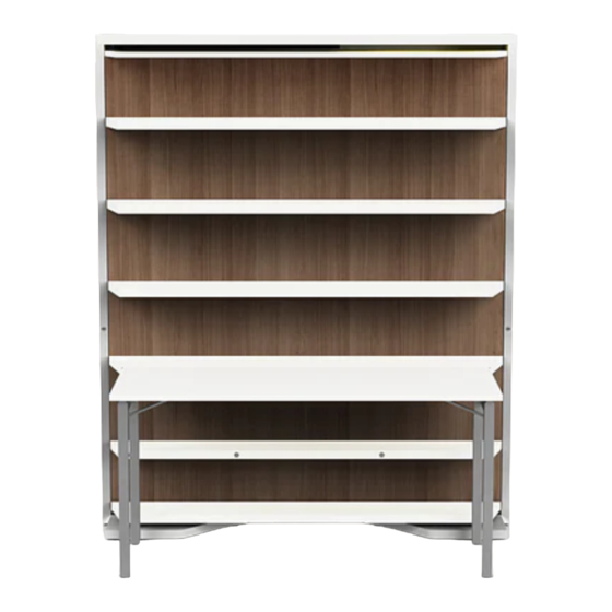
- Page 3 LGM OVERVIEW LGM 01 LGM Tavolo Cannot be installed on carpets or area rugs, if using an area rug it should be placed a minimum of 18 1/2” from front edge of the LGM.
- Page 4 LGM OVERVIEW...
- Page 5 LGM OVERVIEW...
- Page 6 LGM OVERVIEW...
- Page 7 LGM STRUCTURAL HARDWARE CODE QTY. COMPONENT DESCRIPTION 04 L20 Wood screw 3.5 L30 Wood screw 3.5 L16 Wood screw 06 L30 Machine screw 06 L35 Machine screw 10mm L45 Machine bolt Round washer Connected knobs Washer with flat edge 7x36x6...
- Page 8 STRUCTURE ASSEMBLY Screw 8 metal pins (J) into the side vertical panels. (Part A) Fit the Left side to the Base. Tighten cam connectors (K) to the metal pins. (Part B). Part A Part B...
- Page 9 STRUCTURE ASSEMBLY Install the left back panel into the bed structure with the groove facing the center. Use Wood Screw 3.5x30 (B) to attach Backpanel. Install the brown spline into the groove. Bed also available with wide vertical sides. Not shown in these instructions.
- Page 10 STRUCTURE ASSEMBLY Install the second back panel. Do Not Use any Wood Screws Yet. Attach the top to the left side using cam connectors (K).
- Page 11 STRUCTURE ASSEMBLY Attach the right vertical side to the bottom and top using cam connectors (K). Install the remaining screws into the back panels using wood screws 3.5 L30 (B).
- Page 12 STRUCTURE ASSEMBLY Move bed structure to the determined installation location and adjust the structure to be level and plumb. The section of baseboard behind the bed can be removed in order to mount bed flush to the wall.
- Page 13 LEVELING THE FEET To compensate for any floor unevenness, use the adjustable feet on the horizontal bottom panel. Adjust the feet by locating the access hole and use the 4mm allan key. Turn clockwise to push the leveler down, and counterclockwise to pull the leveler up.
- Page 14 WALL BED ATTACHMENT After the unit is level and plumb it should be securely attached to the wall using the metal angle mounting brackets as shown in the images below. A proper wall anchor suitable for the wall’s construction must be selected by the contractor or installer. Caution: The included wall anchors are for solid concrete walls only.
- Page 15 STRUCTURE THE ROTATING STRUCTURE Ensure the height difference between the rotating arm and the base of the structure is 3mm. Adjust bolts if necessary. Fasten the rotating arm to the base of the bed structure using the brass bolt (L)
- Page 16 STRUCTURE THE ROTATING STRUCTURE Insert the pin of the “U” shaped metal extrusion into the hole located in the LEFT panel of the revolving bookshelf. Fasten “U” shaped extrusion with two 3.5 L15 Wood Screws (C).
- Page 17 STRUCTURE THE ROTATING STRUCTURE Adjust lower guide pin up. Later this will be lowered into guide slot...
- Page 18 STRUCTURE THE ROTATING STRUCTURE Assemble rotating structure to the front of the metal base using three 10mm L45 machine bolts (F) and two round washers (I) and one washer with flat edge (I). Note: Attach the bolts (F) just snug, as the left panel will need adjustment later.
- Page 19 STRUCTURE THE ROTATING STRUCTURE Stand the structure and base upright and install the 2nd panel. Install the 6 bolts previously removed, but do not tighten all the way.
- Page 20 STRUCTURE THE ROTATING STRUCTURE Install the top of the rotating unit. Align the brass dowels to the holes in the top. Starting from one side install the 6mm L30 (Code D) machine screws. Gradually tighten the screws until the top pulls tight against the front panels. Now tighten the 6 bolts (g) and the 6 nuts and bolts from step 13.
- Page 21 STRUCTURE THE ROTATING STRUCTURE Install the metal arm support using Brass Bolt (L). Partially install the guide pin (M Top Roller), with the white nylon protruding just past the top to be adjusted later.
- Page 22 STRUCTURE THE ROTATING STRUCTURE Install connected knobs(Code H) to front panel. Install 2 06L30 (Code D) see inset drawing A. inset drawing A...
- Page 23 STRUCTURE THE ROTATING STRUCTURE With two people, lift the rotating assembly onto the pin of the rotating arm. Be careful not to dislodge the ball bearings.
- Page 24 STRUCTURE THE ROTATING STRUCTURE Thread the top guide roller(Code M) into the groove inside the top of the bed structure. 2 and 3. Attach metal support arm to the upper bed structure using brass bolt (Code L) 4. Lower guide pin: Insert the lower roller into the groove on the lower section.
- Page 25 STRUCTURE THE ROTATING STRUCTURE Install the metal shelf supports to the front panel using Code A wood screws 04 L20. Note: the lowest four shelf supports are “cut” special. The flange is narrower than the others. Caution: check the length of the wood screws, they need to be 20mm long.
- Page 26 STRUCTURE THE ROTATING STRUCTURE Install the shelves. Notice the orientation of the holes on the drawing. The shelves should be installed with the screw hole in the lease visible side.
- Page 27 STRUCTURE THE ROTATING STRUCTURE Assemble the three side “wheel Cover” using 4 metal pins (code J) and 4 cams (code K). Screw the provided hardware into the predrilled holes in the front panel and the inside of the “wheel Cover”. Install the “wheel Cover”...
- Page 28 STRUCTURE THE ROTATING STRUCTURE Lift the wooden mattress support onto the metal base. Remove the nuts from the bolts located on the bottom of the springs. Insert the bolt into the slots on the metal base and then tighten nuts onto bolts.
- Page 29 STRUCTURE THE ROTATING STRUCTURE Install the mattress onto the mattress support and secure the mattress with the two nylon straps. Open the mattress support and make any necessary height adjustments to the feet.
- Page 30 TAVALO/ TABLE OPTION...
- Page 31 TAVALO/ TABLE OPTION...
- Page 32 ResourceFurniture.com...
Need help?
Do you have a question about the LGM and is the answer not in the manual?
Questions and answers