Table of Contents
Advertisement
Quick Links
Repair/Parts
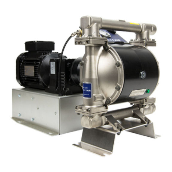
VERDERAIR
VERDERAIR Electric
VERDERAIR
Diaphragm Pumps
Diaphragm
Diaphragm
Models VA
VA- - - EH50,
EH50, VA
VA- - - E2H52,
Models
Models
VA
EH50,
VA
2 2 2 - - - inch,
inch, 3 3 3 - - - inch,
inch, and
and 4 4 4 - - - inch
inch pumps
inch,
inch,
and
inch
in in in explosive
explosive
explosive atmospheres
atmospheres or or or hazardous
atmospheres
page
page for
page
for
for more
more information.
more
information. For
information.
Important Safety
Safety Instructions
Important
Important
Safety
Read all warnings and instructions in this manual and in your
Operation manual before using the equipment. Save
instructions.
instructions.
instructions.
See Technical Data on page 38 for
model information, including Maximum
Working Pressure.
See page 10 for approvals.
Electric - - - Operated
Electric
Pumps
Pumps
E2H52, VA
VA- - - E2H53,
E2H53, VA
VA- - - E2H54
E2H52,
VA
E2H53,
VA
pumps with
with electric
electric drive
pumps
with
electric
hazardous
hazardous (classified)
(classified) locations
(classified)
For
For professional
professional use
professional
Instructions
Instructions
Operated
Operated
E2H54
E2H54
drive for
for fluid
fluid transfer
transfer applications.
drive
for
fluid
transfer
locations unless
locations
unless otherwise
unless
use
use only.
only.
only.
Save these
these
Save
these
applications. Not
Not approved
approved for
applications.
Not
approved
otherwise stated.
otherwise
stated. See
stated.
See Approvals
See
859.0773
Rev.C
EN
for use
use
for
use
Approvals
Approvals
Advertisement
Table of Contents

Subscribe to Our Youtube Channel
Related Manuals for VERDER VERDERAIR VA-EH50


Summary of Contents for VERDER VERDERAIR VA-EH50
- Page 1 Repair/Parts VERDERAIR VERDERAIR VERDERAIR Electric Electric - - - Operated Electric Operated Operated Diaphragm Pumps Pumps Diaphragm Diaphragm Pumps 859.0773 Rev.C Models VA VA- - - EH50, EH50, VA VA- - - E2H52, E2H52, VA VA- - - E2H53, E2H53, VA VA- - - E2H54 E2H54 Models...
-
Page 2: Table Of Contents
Contents Contents Contents Related Manuals ..........2 Pressure Relief Procedure......13 Check Valve Repair ........13 Warnings ............3 Standard Diaphragm Repair ......16 Pump Matrix for VA-EH50 Food Grade Overmolded Diaphragm Repair..... 18 Pumps..........6 Center Section Repair ........20 Pump Matrix for VA-E2H52, VA-E2H53, and Install Compressor Kits......... -
Page 3: Warnings
Warnings Warnings Warnings Warnings The following warnings are for the setup, use, grounding, maintenance, and repair of this equipment. The exclamation point symbol alerts you to a general warning and the hazard symbols refer to procedure-specific risks. When these symbols appear in the body of this manual or on warning labels, refer back to these Warnings. - Page 4 Warnings WARNING PRESSURIZED PRESSURIZED PRESSURIZED EQUIPMENT EQUIPMENT EQUIPMENT HAZARD HAZARD HAZARD Fluid from the equipment, leaks, or ruptured components can splash in the eyes or on skin and cause serious injury. • Follow the Pressure Pressure Relief Pressure Relief Procedure Relief Procedure Procedure when you stop spraying/dispensing and before...
- Page 5 Warnings WARNING THERMAL THERMAL THERMAL EXPANSION EXPANSION HAZARD EXPANSION HAZARD HAZARD Fluids subjected to heat in confined spaces, including lines, can create a rapid rise in pressure due to the thermal expansion. Over-pressurization can result in equipment rupture and serious injury.
-
Page 6: Pump Matrix For Va-Eh50 Food Grade
Pump Matrix for VA-EH50 Food Grade Pumps Pump Matrix Matrix for for VA-EH50 VA-EH50 Food Food Grade Grade Pumps Pumps Pump Pump Matrix VA-EH50 Food Grade Pumps Check the identification plate (ID) for the Configuration Number of your pump. Use the following matrix to define the components of your pump. - Page 7 Pump Matrix for VA-EH50 Food Grade Pumps Diaphragm Diaphragm Diaphragm Material Material Material Connections Connections Connections Drive Drive Drive Options Options Options Certifications Certifications Certifications Food EN 10204 Santoprene Stainless Steel, Standard AC Induction Motor (High Speed DIN 11851, 65 Grade type 2.1 Gear Ratio) with 120V...
-
Page 8: Va-E2H54 High Sanitary Pumps
Pump Matrix for VA-E2H52, VA-E2H53, and VA-E2H54 High Sanitary Pumps Pump Matrix Matrix for for VA-E2H52, VA-E2H52, VA-E2H53, VA-E2H53, and and VA-E2H54 VA-E2H54 Pump Pump Matrix VA-E2H52, VA-E2H53, VA-E2H54 High Sanitary Sanitary Pumps Pumps High High Sanitary Pumps Check the identification plate (ID) for the Configuration Number of your pump. - Page 9 Pump Matrix for VA-E2H52, VA-E2H53, and VA-E2H54 High Sanitary Pumps Diaphragm Diaphragm Diaphragm Material Material Material Connections Connections Connections Drive Drive Drive Options Options Options Certifications Certifications Certifications Buna-N EN 10204 Stainless Steel, Standard AC Induction Motor (High Speed DIN 11851, 50 type 2.1 Gear Ratio) with 120V Air Compressor...
-
Page 10: Approvals
Approvals Approvals Approvals Approvals Approvals Approvals Approvals ✦ Pumps with motor code are approved to: II 2 G Ex h d IIB T3 Gb ✚ Pumps with motor code are approved to: II 2 G Ex h IIB T3 Gb Class I, Div 1, Group D, T3B ★... -
Page 11: Troubleshooting
Troubleshooting Troubleshooting Troubleshooting Troubleshooting • Follow the Pressure Relief Procedure, page • Check all possible problems and causes before before checking or servicing the equipment. disassembly. Problem Cause Solution Problem Problem Cause Cause Solution Solution Pump cycles but will not Pump is running too fast, causing Slow down the controller (VFD) prime and/or pump. - Page 12 Troubleshooting Problem Cause Solution Problem Problem Cause Cause Solution Solution Air consumption is higher A fitting is loose. Tighten. Inspect thread sealant. than expected. Replace. Loose or damaged o-rings or shaft seal. Diaphragm (or backup) ruptured. Replace. Air bubbles in fluid. Suction line is loose.
-
Page 13: Repair
Repair Repair Repair Repair Disassemble Disassemble the Disassemble the Check Check Check Valve Valve Valve NOTE: When reassembling fluid section components, NOTE: NOTE: loosely assemble initially to ensure acceptable alignment. Once all components are in place, tighten 1. Follow the Pressure Relief Procedure, page all clamps. - Page 14 Repair Arrow (A) must point toward outlet manifold. Radiused seating surface must face the ball (7). Large chamfer on O.D. must face o-ring. 859.0773...
- Page 15 Repair Disassemble Disassemble Disassemble the the Flapper Flapper Flapper Check Check Valve Check Valve Valve Reassemble Reassemble the Reassemble the Flapper Flapper Flapper Check Check Valve Check Valve Valve 1. Follow the Pressure Relief Procedure, page 1. Clean all parts and inspect for wear or damage. Disconnect power from the motor.
-
Page 16: Standard Diaphragm Repair
Repair Standard Diaphragm Diaphragm Repair Repair Standard Standard Diaphragm Repair b. Rotate the drive shaft to move the piston fully to the other side. Repeat step 4a. 5. To continue with diaphragm disassembly, see Disassemble the Center Section, page Tools Required Required Tools Tools... - Page 17 Repair Reassemble Reassemble Reassemble the the Standard Standard Diaphragms Standard Diaphragms Diaphragms 4. Clean the female threads of the piston shaft NOTICE NOTICE NOTICE with a wire brush dipped in solvent to remove any residual thread locker. Apply thread-locking After reassembly, allow the thread locker to cure primer and allow it to dry.
-
Page 18: Overmolded Diaphragm Repair
Repair Overmolded Diaphragm Diaphragm Repair Repair Overmolded Overmolded Diaphragm Repair b. Rotate the drive shaft to move the piston fully to the other side. Repeat step 4a. 5. To continue with diaphragm disassembly, see Disassemble the Center Section, page Tools Required Required Tools Tools... - Page 19 Repair Reassemble Reassemble Reassemble the the Overmolded Overmolded Diaphragms Overmolded Diaphragms Diaphragms 4. Clean the female threads of the piston shaft NOTICE NOTICE NOTICE with a wire brush dipped in solvent to remove any residual thread locker. Apply thread-locking After reassembly, allow the thread locker to cure primer and allow it to dry.
-
Page 20: Center Section Repair
Repair Center Section Section Repair Repair Center Center Section Repair 7. Use a 3/4–16 bolt to push out the drive shaft assembly (112). You can also use the bearing bolt (106), but remove the bearing (107) first. Be sure that the groove on the drive shaft remains aligned with the markings in the center section. - Page 21 Repair Reassemble Reassemble Reassemble the the Center Center Center Section Section Section 1. Clean and dry the center housing (101), the 5. Install o-ring (109) to the center housing (101). center of the piston (102) and the drive shaft 6. Apply anti-seize lubricant on the mating edges of (112).
- Page 22 Repair Apply medium-strength (blue) thread locker to threads. Torque to 20–34 N•m (15–25 ft-lb). Lips must face IN IN IN toward the center. Apply anti-seize lubricant liberally on the radial surfaces of the drive shaft assembly. Install the drive shaft assembly with the groove facing up.
- Page 23 Repair Disconnect Disconnect Disconnect the the Motor Motor Motor and and Gearbox Gearbox Gearbox with the gearbox, so begin with step 3. NOTE: Use a hoist and sling to remove motor weight NOTE: NOTE: from the gearbox during removal. 1. Turn off the pump and disconnect power. 2.
- Page 24 Repair Leak Leak Leak Sensor Sensor Repair Sensor Repair Repair The leak sensor can be replaced or re-positioned. Apply air pressure to the pump and use a When properly positioned, the two arrows imprinted soapy solution around the bushing to ensure on two of the flat surfaces of the leak sensor hex an air tight seal.
-
Page 25: Install Compressor Kits
Repair Install Compressor Compressor Kits Kits Install Install Compressor Kits Kits and Accessories, page 37 for compressor kit options. 1. Follow the Pressure Relief Procedure, page 2. Turn off the pump and Disconnect power to the unit. To avoid injury from fire, explosion, or electric shock, all electrical wiring must be done by a 3. -
Page 26: Replace The Compressor
Repair Replace the the Compressor Compressor Replace Replace Compressor To avoid injury from fire, explosion, or electric shock, all electrical wiring must be done by a qualified electrician and comply with all local codes and regulations. 1. Follow the Pressure Relief Procedure, page 2. -
Page 27: Parts
Parts Parts Parts Parts VA - - - EH50 EH50 Pump Pump EH50 Pump 859.0773... - Page 28 Parts VA - - - E2H52 E2H52 Ball Ball Check Check Pump Pump E2H52 Ball Check Pump 859.0773...
- Page 29 Parts VA - - - E2H53 E2H53 Flapper Flapper Pump Pump E2H53 Flapper Pump 859.0773...
- Page 30 Parts VA - - - E2H54 E2H54 Flapper Flapper Pump Pump E2H54 Flapper Pump 859.0773...
- Page 31 Parts Parts/Kits Quick Quick Reference Reference Parts/Kits Parts/Kits Quick Reference Use this table as a quick reference for parts/kits. Go to the pages indicated in the table for a full description of kit contents. Ref. Part Part Description Description Description Qty.
- Page 32 Parts Qty. Qty. Ref. Ref. Part Ref. Part Part Description Description Description Qty. Qty. Ref. Ref. Ref. Part Part Part Description Description Description Qty. Qty. — — — — — — CLAMP, sanitary SCREW, set, 1/2 X 2.25, pkg of 4 819.0504 —...
- Page 33 Parts Center Section Section Center Center Section Sample Configuration Number: Pump Pump Wetted Center Seats Balls Diaphragms Connections Drive Options Certifications Model Size Parts Section VA-E2H 52 S S S 859.0773...
- Page 34 Parts Part Part Part Description Description Description Part Part Part Description Description Description includes Ref HOUSING, center, GEARBOX; assembly; includes plugs 118a, 118b, 122 819.1247 low speed 819.1253 Aluminum 819.1248 medium speed 819.1254 also Stainless Steel; includes o-ring 819.1249 high speed 819.1237 PISTON, assembly —...
- Page 35 Parts Diaphragms Diaphragms Diaphragms Sample Configuration Number: Pump Pump Wetted Seats Balls Diaphragms Connections Drive Center Options Certifications Model Size Parts Section VA-E2H 52 Bolt Bolt- - - Through Bolt Through Diaphragm Through Diaphragm Kits Diaphragm Kits Kits Overmolded Diaphragm Diaphragm Kit Overmolded Overmolded...
- Page 36 Parts Manifold Seals Seals and and Check Check Balls Balls Manifold Manifold Seals Check Balls Sample Configuration Number: Pump Pump Wetted Center Seats Balls Diaphragms Connections Drive Options Certifications Model Size Parts Section VA-E2H 52 Ball Ball Kits Ball Kits Kits Ball Ball...
-
Page 37: Kits And Accessories
Parts Kits and and Accessories Accessories Kits Kits Accessories Center Center Section Center Section Repair Section Repair Tool Repair Tool Kit Tool Kit 819.1272 819.1272 819.1272 HS Compressor Compressor Box Compressor Box Kits Kits Kits 812.0293 812.0293 812.0293 (120 (120 (120 V) V) V) and 812.0295 812.0295... - Page 38 Parts Fluid Section Section Repair Repair Kits Kits for for VA VA- - - E2H52, E2H52, Fluid Section Section Repair Repair Kits Kits for for VA VA- - - E2H52, E2H52, Fluid Fluid Section Repair Kits E2H52, Fluid Fluid Section Repair Kits E2H52,...
-
Page 39: Technical Data
Technical Data Technical Data Data Technical Technical Data VERDERAIR VERDERAIR VERDERAIR Electric Electric- - - Operated Electric Operated Operated Diaphragm Diaphragm Diaphragm Pumps, Pumps, Pumps, Models Models Models VA VA- - - EH50, EH50, VA EH50, VA- - - E2H52, E2H52, E2H52, VA VA- - - E2H53,... - Page 40 Technical Data VERDERAIR VERDERAIR VERDERAIR Electric Electric- - - Operated Electric Operated Operated Diaphragm Diaphragm Pumps, Diaphragm Pumps, Models Pumps, Models Models VA VA- - - EH50, EH50, EH50, VA VA- - - E2H52, E2H52, E2H52, VA VA- - - E2H53, E2H53, E2H53, VA VA- - - E2H54...
- Page 41 Technical Data VERDERAIR VERDERAIR VERDERAIR Electric Electric- - - Operated Electric Operated Operated Diaphragm Diaphragm Diaphragm Pumps, Pumps, Pumps, Models Models Models VA VA- - - EH50, EH50, VA EH50, VA- - - E2H52, E2H52, E2H52, VA VA- - - E2H53, E2H53, VA E2H53, VA- - - E2H54...
- Page 42 Technical Data VERDERAIR VERDERAIR VERDERAIR Electric Electric- - - Operated Electric Operated Operated Diaphragm Diaphragm Pumps, Diaphragm Pumps, Models Pumps, Models Models VA VA- - - EH50, EH50, EH50, VA VA- - - E2H52, E2H52, E2H52, VA VA- - - E2H53, E2H53, E2H53, VA VA- - - E2H54...
- Page 43 Pump Pump Pump Weights* Weights* Weights* Pump Motor/Gearbox Material Standard AC ATEX AC Flameproof AC No Gear- motor Center Model Section VA-EH50 Aluminum Stainless Steel VA-E2H52 Aluminum Stainless Steel VA-E2H53 Aluminum Stainless Steel VA-E2H54 Aluminum Stainless Steel *For compressor codes or 2, add 13 kg (28 Ib)
- Page 44 Technical Data Component/Model U.S. Metric Component/Model Component/Model U.S. U.S. Metric Metric Compressor 28 lb 13 kg Fluid Temperature Temperature Range Range Fluid Fluid Temperature Range NOTICE NOTICE NOTICE Temperature limits are based on mechanical stress only. Certain chemicals will further limit the fluid temperature range.
- Page 45 (rental use excluded) for two years after purchase date. This warranty does not cover failure of parts or components due to normal wear, damage or failure which in the judgement of VERDER arises from misuse. Parts determined by VERDER to be defective in material or workmanship will be repaired or replaced.
- Page 46 Austria Austria Belgium Belgium China China Verder Austria Verder nv Verder Shanghai Instruments and Equipment Co., Ltd Eitnergasse 21/Top 8 Kontichsesteenweg 17 Building 8 Fuhai Business Park No. 299 A-1230 Wien B–2630 Aartselaar Bisheng Road, Zhangjiang Hiteck Park AUSTRIA BELGIUM...
Need help?
Do you have a question about the VERDERAIR VA-EH50 and is the answer not in the manual?
Questions and answers