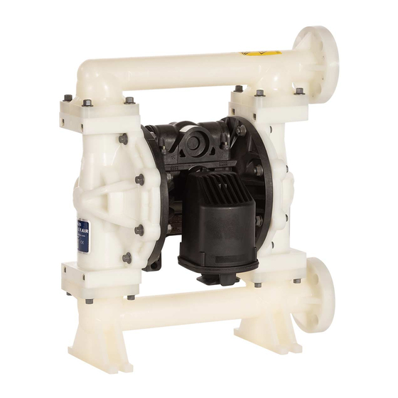
VERDER VERDERAIR VA 25 Repair Parts
Air-operated diaphragm pump
Hide thumbs
Also See for VERDERAIR VA 25:
- Instructions-parts list manual (36 pages) ,
- Manual (36 pages) ,
- Instructions-parts list manual (32 pages)
Table of Contents
Advertisement
Quick Links
Repair/Parts
VERDERAIR VA 25 (HE)
Air-Operated
Diaphragm Pump
1-inch pump with modular air valve for fluid transfer applications.
For professional use only.
See page 3 for model information, including approvals.
125 psi (0.86 MPa, 8.6 bar) Maximum Fluid Working Pressure
125 psi (0.86 MPa, 8.6 bar) Maximum Air Input Pressure
Important Safety Instructions
Read all warnings and instructions in this manual.
Save these instructions.
ti13946a
Hastelloy
Stainless Steel
Aluminum
ti14342a
Polypropylene
Conductive
Polypropylene
PVDF
End
Flange
859.0089
Rev. ZAD
EN
Center
Flange
ti13843a
ti13844a
Advertisement
Table of Contents

Subscribe to Our Youtube Channel
Related Manuals for VERDER VERDERAIR VA 25


Summary of Contents for VERDER VERDERAIR VA 25
- Page 1 Repair/Parts VERDERAIR VA 25 (HE) Air-Operated 859.0089 Rev. ZAD Diaphragm Pump 1-inch pump with modular air valve for fluid transfer applications. For professional use only. See page 3 for model information, including approvals. 125 psi (0.86 MPa, 8.6 bar) Maximum Fluid Working Pressure 125 psi (0.86 MPa, 8.6 bar) Maximum Air Input Pressure...
-
Page 2: Table Of Contents
Contents Related Manuals ......2 Parts ........17 Pump Matrix . -
Page 3: Pump Matrix
Pump Matrix Check the identification plate (ID) for the 17-digit Configuration Number of your pump. Use the following matrix to define the components of your pump. Sample Configuration Number: VA25(HE)AA-SSBNBNTNSS PART NO. CONFIGURATION NO. SERIAL NO. VA25 SS BN BN DATE CODE SERIES MAX WPR PSI-bar... -
Page 4: Atex Certifications
ATEX Certifications Stroke Sensor is certified: All VA25(HE)AA, VA25(HE)CC, VA25(HE)HC, VA25(HE)SA, VA25(HE)SC pumps are certified: II 1 G Ex ia IIA T3 ITS13ATEX27862 II 2 GD Ex h IIC 66°C...135°C Gb Ex h IIIC T135°C Db ATEX T-code rating is dependent on the temperature of the fluid being pumped. Fluid temperature is limited by the materials of the pump interior wetted parts. - Page 5 WARNING EQUIPMENT MISUSE HAZARD Misuse can cause death or serious injury. • Do not operate the unit when fatigued or under the influence of drugs or alcohol. • Do not exceed the maximum working pressure or temperature rating of the lowest rated system component.
- Page 6 WARNING TOXIC FLUID OR FUMES HAZARD Toxic fluids or fumes can cause serious injury or death if splashed in the eyes or on skin, inhaled, or swallowed. • Read MSDS’s to know the specific hazards of the fluids you are using. •...
-
Page 7: Troubleshooting
Troubleshooting Problem Cause Solution Pump cycles but will not prime. Pump is running too fast, causing Lower air inlet pressure. cavitation before prime. Check valve ball severely worn or Replace ball and seat. See page 12. wedged in seat or manifold. Seat severely worn. - Page 8 Problem Cause Solution Air bubbles in fluid. Suction line is loose. Tighten. Diaphragm (and backup) ruptured. Replace. See page 13. Loose manifolds, damaged seats or Tighten manifold bolts or replace manifold o-rings. seats or o-rings. See page 12. Diaphragm shaft bolt o-ring dam- Replace o-ring.
-
Page 9: Repair
Repair Pressure Relief Procedure 4. Remove screws (109, metal pumps) or nuts (112, plastic pumps). Remove the air valve and gasket (108). 5. To repair the air valve, go to Disassemble the Air Valve, step 1, in next section. To install a replace- Trapped air can cause the pump to cycle unexpect- ment air valve, continue with Step 6. - Page 10 NOTE: Apply lithium-based grease whenever instructed NOTE: Repair kits are available. See page 25 to order to grease. Order Verder part number 819.0184. the correct kit(s) for your pump. Air Valve Seal Kit parts are marked with a †. Air Valve Repair Kit parts are 1.
- Page 11 209† 205 212 214 213 211 203 204 210 208† 206† 207 202 208† 207 inlet 206† Apply lithium-based grease. U-cup lips must face piston. 210 Apply lithium-based grease to contact surface. ti18205a . 3. Air valve assembly 7. Grease and install the detent assembly (203) into the 8.
-
Page 12: Check Valve Repair
Check Valve Repair Torque to 90 in-lb (10.2 N•m). See Torque Instructions, page 16. Arrow (A) must point toward outlet manifold. Not used on some models. NOTE: Kits are available for new check valve balls and seats in a range of materials. See page 26 to order kits Aluminum pump in the material(s) desired. -
Page 13: Diaphragms And Center Section
Diaphragms and Center Section b. Plastic Pumps: Use a 1-1/4 socket or box end wrench on the hex of a fluid side diaphragm plate to remove. Then remove all parts of the dia- phragm assembly. See F . 7. Metal Pumps: Remove the bolt (304) from one side of the diaphragm shaft, then remove all parts of that diaphragm assembly. - Page 14 104* 104* HY, SP, BN, VT, and GE models NO and TO (Metal pumps) models (Plastic pumps) ti14037a ti14022a Rounded side faces diaphragm. Apply lithium-based grease. Torque to 20-25 ft-lb (27-34 N•m) at 100 rpm maximum. AIR SIDE markings on diaphragm must face center housing.
- Page 15 Assemble the fluid side plate (13), the diaphragm NOTE: Apply lithium-based grease whenever instructed (15), the backup diaphragm (305, if present), and to grease. Order Verder part number 819.0184. the air side diaphragm plate (14) on the bolt exactly as shown in F .
-
Page 16: Torque Instructions
Torque Instructions 7. To ensure proper seating and extend diaphragm life, attach the second fluid cover with air pressure on the pump. NOTE: Fluid cover and manifold fasteners have a thread-locking adhesive patch applied to the threads. If a. See F . -
Page 17: Parts
Parts see page 30 see page 19 see page 20 see page 26 see page 22 see page 26 see page 24 see page 19 see page 27 see page 28 see page 19 see page 26 see page 21 ti14023a 1 Not used on some models. -
Page 18: Parts/Kits Quick Reference
Parts/Kits Quick Reference Use this table as a quick reference for parts/kits. See pages indicated in table for full description of kit contents. Ref. Part/Kit Description Qty. Ref. Part/Kit Description Qty. Seats; 4-pack, includes 8 o-rings where Center Section; see page 22 needed, see page 26 859.0400 Aluminum... -
Page 19: Fluid Section
Fluid Section Sample Configuration Number Pump Size Fluid Section Air Section Seats Balls Diaphragms Connections Options VA25(HE) Manifold Fasteners (6) Fluid Covers Kits include: Fluid Cover and • 1 fluid cover (3) Manifold Material Description Qty. • 4 o-rings, ptfe (12) Aluminum 859.0033 BOLT, hex Fluid Cover and Manifold... - Page 20 Sample Configuration Number Pump Size Fluid Section Air Section Seats Balls Diaphragms Connections Options VA25(HE) Outlet Manifolds Aluminum Hastelloy and Stainless Kits include: Steel • 1 outlet manifold (4) Kits include: • 3 pipe plugs (8) • 1 outlet manifold (4) •...
- Page 21 Sample Configuration Number Pump Size Fluid Section Air Section Seats Balls Diaphragms Connections Options VA25(HE) Inlet Manifolds Aluminum Hastelloy and Stainless Kits include: Steel • 1 inlet manifold (5) Kits include: • 3 pipe plugs (8) • 1 inlet manifold (5) •...
-
Page 22: Air Section
Air Section Sample Configuration Number Pump Size Fluid Section Air Section Seats Balls Diaphragms Connections Options VA25(HE) Plastic Air Section and P) Aluminum Air Section air valve detail, see page 24 109* *112 108* *108 ‡*105 ‡*106 *102 *103 103* *101 ti14104a *102... - Page 23 Sample Configuration Number Pump Size Fluid Section Air Section Seats Balls Diaphragms Connections Options VA25(HE) Kit 859.0000, Center Section Rebuild (*) Kit 859.0035, Center Shaft Kit All Models All models Kit includes: Kit includes: • 2 pilot valves (101) • 1 center shaft (104) •...
-
Page 24: Air Valve And Data Monitoring
Sample Configuration Number Pump Size Fluid Section Air Section Seats Balls Diaphragms Connections Options VA25(HE) Air Valve and Data Monitoring 209† 205 212 214 213 211 203 204 210 208† 206† 207 202 208† 207 206† Apply lithium-based grease. inlet U-cup lips must face piston. - Page 25 Sample Configuration Number Pump Size Fluid Section Air Section Seats Balls Diaphragms Connections Options VA25(HE) Air Valve Seals (†) Complete Air Valve Replacement Kits All Models Aluminum Kit includes: Kits include: • 2 end cap o-rings (206) • 1 air valve assembly with restrictor (2) •...
-
Page 26: Seats
Sample Configuration Number Pump Size Fluid Section Air Section Seats Balls Diaphragms Connections Options SS BN VA25(HE) Seats Check Balls NOTE: Some kits may not be available for your model. NOTE: Some kits may not be available for your model. See the configurator tool at www.verderair.com or speak See the configurator tool at www.verderair.com or speak with your distributor. -
Page 27: Diaphragms
Diaphragms Sample Configuration Number Pump Size Fluid Section Air Section Seats Balls Diaphragms Connections Options VA25(HE) NOTE: Some kits may not be available for your model. See the configurator tool at www.verderair.com or speak with your distributor. Standard Diaphragms Overmolded Diaphragms Kits include: Kits include: •... - Page 28 Diaphragms (continued) Sample Configuration Number Pump Size Fluid Section Air Section Seats Balls Diaphragms Connections Options VA25(HE) Two-Piece Diaphragms Air and Fluid Plates Kits include: Kits for aluminum, hastelloy, and stainless steel • 8 o-rings, PTFE (12) pumps include: • 2 diaphragms, PTFE (15) •...
-
Page 29: Seat, Check Ball, And Diaphragm Kits
Seat, Check Ball, and Diaphragm Kits Sample Configuration Number Pump Size Fluid Section Air Section Seats Balls Diaphragms Connections Options SS BN VA25(HE) Pump Pump Part No. Material Seats Balls Diaphragms O-Rings Part No. Material Seats Balls Diaphragms O-Rings 859.0415 M/P 859.0131 M/P 859.0587 M/P 859.0132 M/P... -
Page 30: Accessories
Accessories Fluid Pressure Relief Kit 819.6479 Grounding Wire Assembly Kit 819.0157 (for aluminum pumps) Includes ground wire and clamp. Includes pipe bushings, hose adapter, relief valve, and tubing. Standard Pipe Flange Kits 819.6885 - Polypropylene Fluid Pressure Relief Kit 819.0159 819.6886 - Stainless steel (for plastic pumps) 819.6887 - PVDF... -
Page 31: Technical Data
Technical Data Maximum fluid working pressure ........125 psi (0.86 MPa, 8.6 bar) Air pressure operating range . - Page 32 Non-wetted external parts Aluminum (VA25(HE)AA) ......... aluminum, coated carbon steel Hastelloy (VA25(HE)HC) .
- Page 33 Notes 859.0089...
-
Page 34: Customer Services/Guarantee
All VERDER pumps are warranted to the original user against defects in workmanship or materials under normal use (rental use excluded) for two years after purchase date. This warranty does not cover failure of parts or components due to normal wear, damage or failure which in the judgement of VERDER arises from misuse. - Page 35 é...
Need help?
Do you have a question about the VERDERAIR VA 25 and is the answer not in the manual?
Questions and answers