Table of Contents
Advertisement
Quick Links
P
Instruction Manual
Pulse, Open Collector, NPN, PNP, TTL, Switch Contact,
Sine Wave (Coil), Square Wave Inputs
5, 10, or 24 V Flowmeter Power Supply
K-Factor, Internal Scaling, or External Calibration
Start, Batch, Pause, & Stop with Front Panel Buttons
Display Batch Total + Rate, Grand Total, Batch Count or Preset
Single or Multi-Stage Batching with up to 8 Relays
Automatic Overflow Protection
Manual Control or Automatic Batching
Dual-Line Display
NEMA 4X and IP65 Rated Front Panel
UL Listed & CE Marked
Display Features 0.6" & 0.46" Digits
Six Full Digits on Each Line
Optional Superluminous Sunlight Readable Display
Free USB Programming Software & Cable
2 or 4 Relays + Isolated 4-20 mA Output Options
Input Power Options Include 85-265 VAC or 12-24 VDC
Isolated 24 VDC @ 200 mA Transmitter Power Supply
Modbus
Find Quality Products Online at:
V
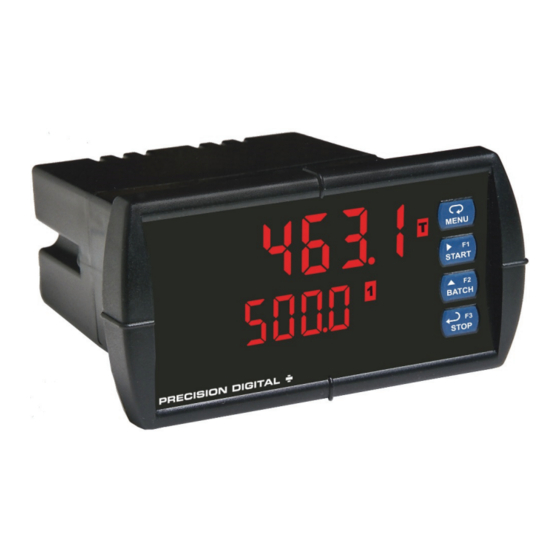
PD6310 Pulse Input Batch Controller
RO
U
®
RTU Communication Protocol Standard
GlobalTestSupply
www.
P
V
R
S
USB Install
Batch Controller
.com
sales@GlobalTestSupply.com
U
®
ERIES
Advertisement
Table of Contents

Subscribe to Our Youtube Channel
Related Manuals for Precision Digital Corporation PROVU PD6310


Summary of Contents for Precision Digital Corporation PROVU PD6310
- Page 1 PD6310 Pulse Input Batch Controller Instruction Manual ® ERIES USB Install Batch Controller Pulse, Open Collector, NPN, PNP, TTL, Switch Contact, Sine Wave (Coil), Square Wave Inputs 5, 10, or 24 V Flowmeter Power Supply K-Factor, Internal Scaling, or External Calibration ...
- Page 2 Limited Warranty Precision Digital Corporation warrants this product against defects in material or workmanship for the specified period under “Specifications” from the date of shipment from the factory. Precision Digital’s liability under this limited warranty shall not exceed the purchase value, repair, or replacement of the defective unit.
-
Page 3: Table Of Contents
PD6310 Pulse Input Batch Controller Instruction Manual Table of Contents Table of Contents ----------------------------------------- 3 Reset ------------------------------------------------ 29 Batch Start Mode (mode) ------------------------------ 30 Table of Figures ------------------------------------------- 4 Calibrating the Controller with External Source Introduction ------------------------------------------------- 4 ... -
Page 4: Table Of Figures
PD6310 Pulse Input Batch Controller Instruction Manual Troubleshooting ----------------------------------------- 49 Factory Defaults & User Settings ---------------------- 50 Troubleshooting Tips -------------------------------------- 52 Diagnostics Menu (diag) -------------------------------- 49 Determining Software Version ------------------------- 49 EU Declaration of Conformity ----------------------- 53 ... -
Page 5: Ordering Information
PD6310 Pulse Input Batch Controller Instruction Manual Ordering Information Standard Models 85-265 VAC Model 12-24 VDC Model Options Installed PD6310-6R2 PD6310-7R2 2 relays (PD1102*) PD6310-6R4 PD6310-7R4 4 relays (PD1104*) PD6310-6R5 PD6310-7R5 2 relays & 4-20 mA output (PD1105*) PD6310-6R7 PD6310-7R7 4 relays &... -
Page 6: Specifications
PD6310 Pulse Input Batch Controller Instruction Manual Specifications Except where noted all specifications apply to operation at +25°C. Terminals P+ & P-: 24 VDC 10%. 12-24 VDC Isolated General Transmitter powered models selectable for 24, 10, or 5VDC Power Supply supply (internal jumper J4). -
Page 7: Batch Controller Rate/Totalizer Display
PD6310 Pulse Input Batch Controller Instruction Manual Multi-Point 2 to 32 points Grand Total Up to seven, user selectable under setup Linearization Alarms menu. Any set point can be assigned to grand total and may be programmed Low-Flow 0-999999 (0 disables cutoff function) anywhere in the range of the controller for Cutoff grand total alarm indication. -
Page 8: Isolated 4-20 Ma Transmitter Output
PD6310 Pulse Input Batch Controller Instruction Manual Relay Reset User selectable via front panel buttons, External 35 VDC maximum digital inputs, or PC Loop Power Supply 1. Automatic reset only (non-latching), when the input passes the reset point Output Loop Power supply Minimum Maximum or total is reset to zero. -
Page 9: Compliance Information
PD6310 Pulse Input Batch Controller Instruction Manual Compliance Information Safety UL & c-UL Listed USA & Canada UL 508 Industrial Control Equipment UL File Number E160849 Front Panel UL Type 4X, NEMA 4X, IP65; panel gasket provided Low Voltage EN 61010-1:2010 Directive Safety requirements for measurement, control, and laboratory use Electromagnetic Compatibility... -
Page 10: Safety Information
PD6310 Pulse Input Batch Controller Instruction Manual Safety Information CAUTION: Read complete WARNING: Risk of electric shock instructions prior to installation and or personal injury. operation of the controller. Hazardous voltages exist within enclosure. Installation and service should be performed only by trained service personnel. -
Page 11: Mounting Dimensions
PD6310 Pulse Input Batch Controller Instruction Manual Mounting Dimensions Figure 2: Controller Dimensions - Side Figure 3: Controller Dimensions - Top View View Transmitter Supply Voltage Selection (P+, P-) All controllers, including models equipped with the 12-24 VDC power option, are shipped from the factory configured to provide 24 VDC power for the transmitter or sensor. -
Page 12: Connections
PD6310 Pulse Input Batch Controller Instruction Manual Connections All connections are made to removable screw terminal connectors located at the rear of the controller. Use copper wire with 60°C or 60/75°C insulation for all line voltage connections. Observe all safety regulations. Electrical wiring should be performed in accordance with all applicable national, state, and local codes to prevent damage to the Caution! -
Page 13: Pulse Signal Connections
PD6310 Pulse Input Batch Controller Instruction Manual Pulse Signal Connections Signal connections are made to a six-terminal connector labeled SIGNAL on Figure 7. The COM (common) terminal is the return for the input signals. The following figures show examples of signal connections. Setup and programming is performed through the front panel buttons. -
Page 14: Switching Inductive Loads
PD6310 Pulse Input Batch Controller Instruction Manual Switching Inductive Loads The use of suppressors (snubbers) is strongly recommended when switching inductive loads to prevent disrupting the microprocessor’s operation. The suppressors also prolong the life of the relay contacts. Suppression can be obtained with resistor-capacitor (RC) networks assembled by the user or purchased as complete assemblies. -
Page 15: 4-20 Ma Output Connections
PD6310 Pulse Input Batch Controller Instruction Manual 4-20 mA Output Connections Connections for the 4-20 mA transmitter output are made to the connector terminals labeled MA OUT. The 4-20 mA output may be powered internally or from an external power supply. 24 V 24 V MA OUT... -
Page 16: Interlock Relay Feature
PD6310 Pulse Input Batch Controller Instruction Manual Interlock Relay Feature As the name implies, the interlock relay feature reassigns one, or more, alarm/control relays for use as interlock relay(s). Interlock contact(s) are wired to digital input(s) and trigger the interlock relay. This feature is enabled by configuring the relay, and relative digital input(s) (see page 36). -
Page 17: Basic Operation And Programming
PD6310 Pulse Input Batch Controller Instruction Manual Basic Operation and Programming The PD6310 has been factory calibrated to read input frequency in Hz (pulses/sec). The calibration equipment is certified to NIST standards. Overview Most setup and programming is done through the front panel buttons. There is one switch located to the right of the input connector, which must be configured according to the input level and type. -
Page 18: Controller Operation
PD6310 Pulse Input Batch Controller Instruction Manual Controller Operation The PD6310 accepts pulses (e.g. ±40mV to ± 8V), square wave (0-5, 0-12V, or 0-24V), open collector NPN, PNP, TTL, or switch contact signals. These signals are scaled to represent rate in engineering units from -99999 to 999999. They may be scaled with a K-factor to represent a total for the batch, and grand total. -
Page 19: Batch Control Operation Example
PD6310 Pulse Input Batch Controller Instruction Manual Batch Control Operation Example The following example shows how two stage batch control functions with a PD6310. This setup will establish a 55 gallon preset for the batch, with a main valve (high flow) that will close at 50 gallons, and a trickle valve (low or restricted flow) that will close at 55 gallons. - Page 20 PD6310 Pulse Input Batch Controller Instruction Manual GlobalTestSupply www. .com Find Quality Products Online at: sales@GlobalTestSupply.com...
-
Page 21: Meterview ® Pro Software
PD6310 Pulse Input Batch Controller Instruction Manual ® MeterView Pro Software The meter can also be programmed using the PC-based MeterView Pro software included with the meter. This software can be installed on any Microsoft® Windows® (XP/Vista/7/8/10) computer by connecting the meter’s onboard USB. -
Page 22: Display Functions And Messages
PD6310 Pulse Input Batch Controller Instruction Manual Display Functions and Messages The controller displays various functions and messages during setup, programming, and operation. The following table shows the main menu functions and messages in the order they appear in the menu. Display Parameter Action/Setting... - Page 23 PD6310 Pulse Input Batch Controller Instruction Manual Display Parameter Action/Setting Display Parameter Action/Setting Description Description Latching- Set relay for latching Display 1 Program display 1 value Lt-CLr Dis 1 cleared operation with manual reset Out 1 Output 1 Program output 1 value only after alarm condition (e.g.
-
Page 24: Setting Numeric Values
PD6310 Pulse Input Batch Controller Instruction Manual Main Menu Map The main menu consists of the most commonly used functions: Setup, Reset, Control, and Password. Press Menu button when a batch is not running to enter Programming Mode then press the Up arrow button to scroll main menu. -
Page 25: Setting Up The Batch Controller (Setup)
PD6310 Pulse Input Batch Controller Instruction Manual Setting Up the Batch Controller (setup) The Setup menu is used to select: 1. Input signal the controller will accept 2. Enable or disable totalizer and batching features 3. Select the display units/tags 4. -
Page 26: Scaling And Calibration
PD6310 Pulse Input Batch Controller Instruction Manual Scaling and Calibration It is very important to read the following information, before proceeding to program the controller: There is no need to recalibrate the controller when first received from the factory. ... -
Page 27: Setting The Decimal Point (Dec Pt)
PD6310 Pulse Input Batch Controller Instruction Manual Setting the Decimal Point (dEc pt) The decimal point may be set with up to five decimal places or with no decimal point at all. The rate, total, and grand total decimal points are independent. Press the Up arrow to move the decimal point one place to the left. -
Page 28: Input Calibration Method (Incal)
PD6310 Pulse Input Batch Controller Instruction Manual Input Calibration Method (InCAL) There are three methods of calibrating (or scaling) the display to show the correct engineering units. Use the Factor menu to enter a K-Factor. (Pulse input models only.) ... -
Page 29: Scaling The Controller (Scale)
PD6310 Pulse Input Batch Controller Instruction Manual Scaling the Controller (SCALE) The process inputs (4-20 mA and 10 VDC) and frequency inputs can be scaled to display the process variable in engineering units. A signal source is not needed to scale the controller; simply program the inputs and corresponding display values. -
Page 30: Batch Start Mode (Mode)
PD6310 Pulse Input Batch Controller Instruction Manual Batch Start Mode (mode) The batch controller may operate in manual or automatic mode. In manual mode, the controller operates as defined in Controller Operation as described on page 18. In automatic mode, the batch process will automatically begin after a completed batch. -
Page 31: Setting The Display Parameter & Intensity (Dsplay)
PD6310 Pulse Input Batch Controller Instruction Manual Setting the Display Parameter & Intensity (dsplay) Display line 1 ( line 1 ) can be programmed to display: 1. Display total 2. Display grand total 3. Toggle rate and total 4. Toggle rate and grand total 5. -
Page 32: Setting The Relay Operation (Relay)
PD6310 Pulse Input Batch Controller Instruction Manual Setting the Relay Operation (relay) This menu is used to set up the operation of the relays. During setup, the relays do not follow the input and they will remain in the state found prior to entering the Relay menu. -
Page 33: Relay Assignment (Assign)
PD6310 Pulse Input Batch Controller Instruction Manual Relay Assignment (Assign) The relays can be assigned to any of the following parameters: 1. Rate for low or high alarm indication 2. Total for batch control relays 3. Grand total for alarm indication Assign preclose if multiple relays are assigned. -
Page 34: Programming Alarm Set And Reset Points
PD6310 Pulse Input Batch Controller Instruction Manual Programming Alarm Set and Reset Points High alarm indication: program set point above reset point. Low alarm indication: program set point below reset point. The deadband is determined by the difference between set and reset points. Minimum deadband is one display count. -
Page 35: Relay Operation Details
PD6310 Pulse Input Batch Controller Instruction Manual Relay Operation Details Overview The relays of the controller can serve three roles, as batch control relays for single or multi-stage batching, as rate, or grand total alarm, or as a sampling relay based on grand total or rate alarm. These capabilities include front panel alarm status LEDs and 2 or 4 internal relays and/or 4 external relays expansion module. -
Page 36: Automatic Reset (Auto)
PD6310 Pulse Input Batch Controller Instruction Manual Automatic Reset (Auto) Automatic reset only In this application, the controller is set up for automatic reset Condition Relay (non-latching relay). Acknowledging the alarm while it is still Normal present has no effect on either the LED or the relay. When the Alarm alarm finally goes away, the relay automatically resets and the Ack (No effect) -
Page 37: Sample Relay Operation
PD6310 Pulse Input Batch Controller Instruction Manual Sample Relay Operation The sampling function allows the operator to set a set point for a “sampling” relay. This can be done for the rate, total, or grand total. Each time the relay reaches the set point, it will close that relay’s contacts for a programmed period of time A rate sampling relay will activate for the sample time ( sam t ), up to 600.0 seconds, every time the set point rate is reached. -
Page 38: Rate Relay Sampling Operation
PD6310 Pulse Input Batch Controller Instruction Manual Rate Relay Sampling Operation When the signal crosses the set point, the relay trips and the sample time starts. After the sample time has elapsed, the relay resets. The cycle repeats every time the set point is crossed, going up for high alarms and going down for low alarms. -
Page 39: Time Delay Operation
PD6310 Pulse Input Batch Controller Instruction Manual Time Delay Operation The following graphs show the operation of the time delay function. When the signal crosses the set point, the On time delay timer starts and the relay trips when the time delay has elapsed. -
Page 40: Reset Menu (Reset)
PD6310 Pulse Input Batch Controller Instruction Manual Reset Menu (reset) The Reset menu is used to reset the total, grand totals, batch count, maximum, or minimum reading (peak or valley) reached by the process; both maximum and minimum may be reset at the same time by selecting “reset high &... -
Page 41: Grand Total Reset Password & Non-Resettable Total
PD6310 Pulse Input Batch Controller Instruction Manual Grand Total Reset Password & Non-Resettable Total The grand total can be password-protected to prevent unauthorized total resets. The grand total can be programmed as a non-resettable total by entering the password “050873”. Once the Grand Total has been programmed as “non-resettable”... -
Page 42: Advanced Operation And Programming
PD6310 Pulse Input Batch Controller Instruction Manual Advanced Operation and Programming In addition to the functions described in Controller Operation on page 18, the following advanced operation and display features may be programmed. Configuring these features may disable some default batch controller features, or make running a batch operation impossible. These functions should only be used by users who are sure of their need in their application. - Page 43 PD6310 Pulse Input Batch Controller Instruction Manual Display Parameter Action/Setting Display Parameter Action/Setting Total count Set the batch to count up 4 mA Enter mA output value Tot C 4 nmA to or down from the output read by milliamp meter preset with at least 0.001 mA resolution...
-
Page 44: Function Keys Operation
PD6310 Pulse Input Batch Controller Instruction Manual Function Keys Operation During operation, the programmable function keys operate according to the way they have been programmed in the Advanced Features – User menu. The following table shows the default setting for each of the function keys. -
Page 45: Noise Filter (Filter)
PD6310 Pulse Input Batch Controller Instruction Manual Noise Filter (filter) The noise filter is available for unusually noisy signals that cause an unstable process variable display. The noise filter averages the input signal over a certain period. The filter level determines the length of time over which the signal is averaged. -
Page 46: Select Menu (Select)
PD6310 Pulse Input Batch Controller Instruction Manual Select Menu (SElEct) The Select menu is used to select the signal input conditioning applied to the input (linear, square root, or programmable exponent, low-flow cutoff, and analog output programming. The multi-point linearization is part of the linear function selection. -
Page 47: Analog Output Programming (Aoutpr)
PD6310 Pulse Input Batch Controller Instruction Manual Analog Output Programming (AoutPr) The Analog Output Programming menu is used to program the behavior of the 4-20 mA output. The following parameters and functions are programmed in this menu: 1. Source: Source for generating the 4-20 mA output (e.g. PV) 2. - Page 48 PD6310 Pulse Input Batch Controller Instruction Manual Function Keys & Digital I/O Available Settings Refer to the following table for descriptions of each available function key or digital I/O setting. Display Description Display Description Disable the selected function key or Starts the batch process disabl Start...
-
Page 49: Troubleshooting
PD6310 Pulse Input Batch Controller Instruction Manual Troubleshooting Due to the many features and functions of the controller, it’s possible that the setup of the controller does not agree with what an operator expects to see. If the controller is not working as expected, refer to the Diagnostics menu and recommendations below. Diagnostics Menu (diag) The Diagnostics menu is located in the Advanced Features menu, to access Diagnostics menu see Advanced Operation and Programming, page 42. -
Page 50: Factory Defaults & User Settings
PD6310 Pulse Input Batch Controller Instruction Manual Factory Defaults & User Settings The following table shows the factory setting for the major programmable parameters on the controller. Parameter Display Default Setting Parameter Display Default Setting Relay 1 Input type Pulse Input Automatic Act 1... - Page 51 PD6310 Pulse Input Batch Controller Instruction Manual Parameter Display Default Setting Parameter Display Default Setting Display 2 Parity Even Parity 1000.0 Dis 2 analog out Byte-to-byte 010 (0.1 sec) t-byt Output 2 timeout 20.000 mA Out 2 value F1 function Start Source analog...
-
Page 52: Troubleshooting Tips
PD6310 Pulse Input Batch Controller Instruction Manual Troubleshooting Tips Symptom Check/Action Check power at power connector No display at all Controller is password-protected, enter correct six-digit password Not able to change setup or to unlock programming, Locd is displayed Check: Controller displays error 1.
Need help?
Do you have a question about the PROVU PD6310 and is the answer not in the manual?
Questions and answers