
Related Manuals for Watts BLUCHER Connected Roof


Summary of Contents for Watts BLUCHER Connected Roof
- Page 1 REV. 01 / OCTOBER 2020 USER MANUAL & INSTALLATION GUIDE BLÜCHER Connected Roof ® INTELLIGENT BALCONY ROOF & PARKING...
-
Page 2: Table Of Contents
Content Introduction ........................... 3 Scope of delivery ........................... 4 Safety instructions and regulations..................... 4 Technical specification ......................... 5 4.1 Product overview ........................5 4.2 Gateway specifications ......................6 4.3 Monitor specifications ......................7 Mechanical installation ......................... 7 5.1 Gateway ..........................7 5.2 Monitor .......................... -
Page 3: Introduction
Introduction Thank you for buying this BLÜCHER Connected Roof product. We hope that it will live up to ® your expectations and make monitoring your roof performance easier. All documents related to this product can be found at www.blucher.com. BLÜCHER Connected Roof allows you to easily supervise the performance of your roof. -
Page 4: Scope Of Delivery
Scope of delivery Please carefully check all components in the box. Should something be missing, contact your dealer at once. Gateway: Item Description Quantity Gateway Connected Roof Gateway Power supply 5VDC, 1A SD Card Micro SDHC, Class 4, 4 GB Antenna 868 MHz SMA connection Quick start... -
Page 5: Technical Specification
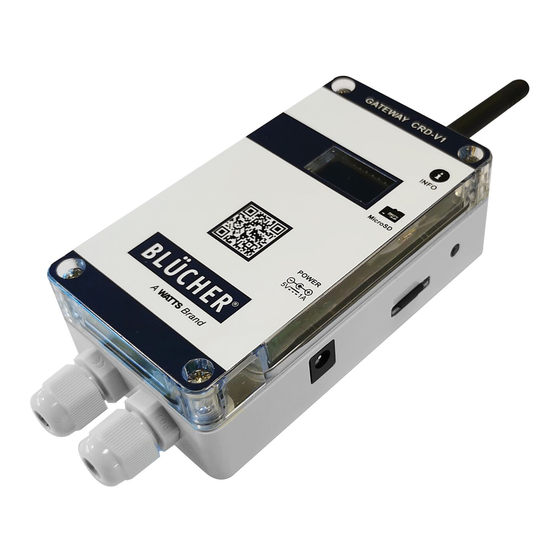
Technical specification 80 mm Product overview GATEWAY 1. Antenna 2. Info button 3. SD card 4. Input for power supply 5. Relay output 6. Internal power supply 7. Modbus 8. Jumper switch MONITOR 9. Mounting bracket 10. Level sensor 11. Monitor ID REV. -
Page 6: Gateway Specifications
Gateway specifications Power supply Voltage 5V DC 1A Nominal power 0,5 W Electrical protection class Class 3 Wireless Frequency 868 MHz Antenna connector Signal range Up to 1500m in free line of sight User input Push button Display Type 0.96” OLED Size 128*64 dot SD card... -
Page 7: Monitor Specifications
Monitor specifications Power supply Battery Lithium battery LS 14500 3.6V (internal) AA Battery life Up to 10 years Level Sensor Sensor electrodes Stainless A2 Enclosure IP protection IP68 Material Anti-UV PC Size 120 x 65 x 60mm Environmental Working temperature -35°C - 85°C Storage temperature -35°C - 85°C... - Page 8 Mounting instructions To mount the enclosure: 60 mm Min. 50 mm To acces Micro SD card 35 mm Unscrew the 4 no. screws on the front cover, then remove Ensure there is enough free space around the unit to the front cover to access the mounting holes. The mounting enable access to the SD card, and to allow space for holes are Ø4 mm, and screws are not included.
- Page 9 Electrical wiring In the bottom of the Gateway you can make three different electric wire connections - Relay, Internal power and Modbus. Below you will find the different ways to set it up. Relay Internal power Modbus Relay can be wired as NO or NC. As an alternative to the power If connection to a Modbus RTU BMS connector on the right side of the...
-
Page 10: Monitor
Monitor We recommend that one Monitor is installed next to each drain on your roof. Monitors should be installed at the primary drainage system and not at emergency outlets and drains. This gives the system the best conditions to evaluate the performance of the drainage system. BLÜCHER CONNECTED ROOF - REV. - Page 11 The Monitor should ideally be installed at the same invert level as the roof drain, giving the system the best conditions to measure the right water level. If this is not possible, and the Monitor ends up higher/lower than the roof drain, you will need to offset the water levels on the Monitor in the config file (see chapter 7.5).
-
Page 12: Commissioning
Commissioning Prior to commissioning, ensure that all Monitors have been installed and the Gateway is mounted and wired according to the previous chapter. 1. Ensure power is OFF* 2. Remove SD card from the Gateway and open the Config file in an editor 3. -
Page 13: Configuration File
Configuration file The config file has sections that must be parameterized. All parameters are described in detail in appendix 13. Description Monitor ID’s (Mandatory) Pair all relevant monitor ID’s. Monitor ID is unique and found on the Monitor Label. One Gateway supports up to 16 Monitors. -
Page 14: Functions
Functions Display The display provides information on measurement values, diagnostics, and system information. 7.1.1 Menu structure The menu is divided into 3 sections: start-up, waiting for data, and operation. During start-up, the Gateway software version can be read. Every time the Gateway has been re-booted it will wait up to 30 minutes until the first Monitor has been detected. -
Page 15: Menu Content
7.1.2 Menu content REV. 01 - OCTOBER 2020 - BLÜCHER CONNECTED ROOF ®... -
Page 16: Display Information
7.1.3 Display information Symbol Description Monitor ID XXXXX Unique ID on the Monitor, must be set-up in configuration file Test mode When symbol is visible, Monitor is in Test mode. When lines are unconnected, relay is OFF Relay status When lines are connected, relay is ON <5% (6 months) - Plan Monitor change for the near future <20% (2 years) Monitor... -
Page 17: Relay
Relay The relay functionality is parametrized in the Config file. Relay modes Default mode Alarm roof Blocked drain, Blocked sensor Alarm Monitor Low battery, Lost connection, Internal leak Alarm Roof Blocked drain, Blocked sensor, Low battery, Lost connection, and Monitor Internal leak Temp One setpoint For application where only one setpoint is needed... -
Page 18: Measurement Values
Measurement values 7.4.1 Water Level Water level is measured in increments from sensor pin 1 to 5, 10 mm corresponding to 0-42mm water 10 mm level. Water level information is 10 mm updated every 30 minutes, or if the 6 mm water level values change. - Page 19 Roof alarm settings To compensate for different roof designs and conditions the behavior of the default algorithm can be customized. This is to avoid unwanted alarms that relate to e.g. roof design flaws. You can offset the values at each monitor in the configuration file. This is done in “ROOF ALARM SETTINGS”.
-
Page 20: Systems Diagnostics
7.5.2 Monitor Systems Diagnostics Monitor systems diagnostics Lost connection The RF alarm is set to appear whenever no communication/signal between a Monitor and Gateway hasn’t been registered for more than 40 hours. Battery alarm Appears if Monitor’s battery voltage goes below 2.4V or the battery level is below 20%. -
Page 21: Modbus Interface
Modbus interface Supported function codes Function code Command text 03 (03hex) Read holding registers 04 (04hex) Read input registers 06 (06hex) Write single register 16 (10hex) Write multiple registers Modbus Termination Jumper switch position Description Internal termination resistor is connected Internal termination resistor is disconnected NB. -
Page 22: Service And Maintenance
Service and maintenance We recommend regular service and maintenance around the area of a drain with a Monitor. Dirt and other obstructions can affect the performance of your drainage system and the BLÜCHER Connected Roof system. BLÜCHER CONNECTED ROOF - REV. 01 - OCTOBER 2020 ®... -
Page 23: Troubleshooting
Troubleshooting In this section we have listed possible issues and how to troubleshoot. Issue - SD card Cause Action Gateway reports: ”SD card Missing SD card Insert SD card missing” File system corrupted Format SD card Defect SD card Insert new SD card Add config file to SD card or Config file missing Check the file name: Config.ini... -
Page 24: Disclaimer
Disclaimer BLÜCHER offers its Connected Roof Product for enhancing the daily supervision of your roof performance. However, the BLÜCHER’s liability must be understood as limited by decreasing prevalence order as follow: - The present DISCLAIMER statements - The BLÜCHER’s General Terms and Conditions of Sale Limited Warranty Product Disclaimer * BLÜCHER’s Connected Roof Product is under a limited warranty intended to cover the material defects of the product device only, for a period in accordance with our General... -
Page 25: Appendix - Configuration File Parameters
Appendix – Configuration file parameters Monitor ID ID_1 - ID_16 1-65535 Unique Monitor ID. The ID can be read on the Monitor label. Relay settings RELAY_MODE OFF, [Factory setting: OFF] ALARM_ROOF, ALARM_MONITOR, ALARM_ROOF_ MONITOR, TEMP_ONESETPOINT, TEMP_TWOSETPOINTS RELAY_TEMP_HYSTERESIS 0 to 5 (°C) [Factory setting: 1] RELAY_TEMP_SETPOINT_1 -10 to 15 (°C) -
Page 26: Appendix - Modbus Tables
Appendix – Modbus tables Table 1. Modbus registers are grouped by sensor index number Modbus sensor object object size, index name index value type range and unit address offset 1 type access offset 1st character 00101 8-15 2nd character 00101 device tag string of 32 ASCII characters …... - Page 27 Table 2. Modbus registers are grouped by parameter type (the values are mirrored from the corresponding registers in the Table 1) Modbus sensor object object index name index value type range and unit size, bit address offset 1 type access offset input 1st character...
- Page 28 Blocked drain alarm - Monitor 1 bool 12951 Blocked drain alarm - Monitor 2 bool 12951 Blocked drain alarm - Monitor 3 bool 12951 Blocked drain alarm - Monitor 4 bool 12951 Blocked drain alarm - Monitor 5 bool 12951 Blocked drain alarm - Monitor 6 bool 12951...
- Page 29 … … diagnostic sensor signal uint16 0 ... 40 13901 … … diagnostic sensor signal uint16 0 ... 40 13916 … … diagnostic internal leak uint16 0 ... 255 14001 … … diagnostic internal leak uint16 0 ... 255 14016 …...
- Page 30 Table 3. Modbus registers of the Gateway system Modbus object object size, name index value type range and unit address offset1 type access offset SRDP protocol version2 uint8 A (0 … 256) 00001 8-15 uint8 B (0 … 256) 00001 HW version2 uint8 A (0 …...
- Page 31 REV. 01 - OCTOBER 2020 - BLÜCHER CONNECTED ROOF ®...
- Page 32 “The BLÜCHER Drain Roof range is easily connected to the ® BLÜCHER EuroPipe pipework system - offering you a safe and ® complete roof drainage system“. • Easy to handle • BIM/CAD • Light weight • Dimensioning • Fast and easy software installation •...
Need help?
Do you have a question about the BLUCHER Connected Roof and is the answer not in the manual?
Questions and answers