Table of Contents
Advertisement
Quick Links
OWNER'S AND USER'S MANUAL
MTOL+
Turbidimeter
TM
Models 28052 & 28053
Catalog No. 29290
Rev 3 06/2020
Read Manual and all product labels BEFORE
using the equipment. Do not use unless you
know the safe and proper operation of this
equipment. Keep this Manual available for
easy access by all users. Replacement
Manuals are available at HFscientific.com
HF scientific
16260 Airport Park Drive
Suite 140
Ft. Myers, FL 33913
Phone: 239-337-2116
Fax: 239-454-0694
Toll-free: 888-203-7248
E-Mail: HF.Info@WattsWater.com
Website: HFscientific.com
Advertisement
Table of Contents

Related Manuals for Watts HF scientific 28052


Summary of Contents for Watts HF scientific 28052
- Page 1 OWNER’S AND USER’S MANUAL MTOL+ Turbidimeter Models 28052 & 28053 HF scientific 16260 Airport Park Drive Suite 140 Read Manual and all product labels BEFORE Ft. Myers, FL 33913 using the equipment. Do not use unless you Phone: 239-337-2116 know the safe and proper operation of this Fax: 239-454-0694 equipment.
- Page 2 Catalog No. 29290 Rev 3 06/2020...
- Page 3 DECLARATION OF CONFORMITY Application of Council Directive Standards to Which Conformity is Declared: Product Safety – Tested and passed: LC (Part 1: General Requirements UL61010-1 Issued May 11, 2012, Ed 3 and CAN/CSA C22.2 #61010-1 issued May 11, 2012) Manufacturer’s Name: HF scientific, inc.
- Page 4 Attention Owners and Users Thank you for purchasing the MTOL+™ turbidimeter. This equipment will provide safe and productive operation as long as it is installed, used, maintained, and serviced in accordance with the instructions in this manual and is properly maintained. Importantly, unless the user is adequately trained and supervised, there is a possibility of death, serious personal injury, property damage or damage to the equipment.
- Page 5 Catalog No. 29290 Rev 3 06/2020...
-
Page 6: Table Of Contents
Table of Contents Section Page Understanding Safety Information ............1 Specifications ..................2 Overview ....................3 1.1 The MTOL+ ................. 3 1.2 The Display ................4 1.3 The Touchpad ..............4 1.4 Vapor Purge ................ 4 Unpacking and Inspection ..............5 Installation .................... - Page 7 Table of Contents (continued) Section Page 4.2.16 Download Logged Files ..........35 4.2.17 Date and Time ............... 35 4.2.18 Update Software ............38 Calibrating the MTOL+, CAL Mode .......... 40 4.3.1 Calibration Standards ............ 40 4.3.1.1 Alternate Ranges ..........40 4.3.2 Indexing Calibration Cuvettes ........
-
Page 8: Understanding Safety Information
Understanding Safety Information This manual contains safety and use instructions that must be followed during the installation, commissioning, operation, care and maintenance, and service of the MTOL+. All responsible personnel must read this manual prior to working with this instrument and should familiarize themselves with the following safety symbols, signals, and pictorials. -
Page 9: Specifications
Specifications Measurement Range 0 – 100 NTU, factory configured Model #28052 (Infrared) & Model #28053 (White Light) 0-10 NTU & 0-1000 NTU optional ranges (loaded on USB thumb drive) Accuracy ±2% of reading or ±0.02 NTU below 40 NTU whichever is greater (0-100 and 0-1000 ranges) ±5% of reading above 40 NTU (0-100 and 0-1000 NTU ranges) ±2% of reading or ±0.02 NTU (0-10 NTU range) -
Page 10: Overview
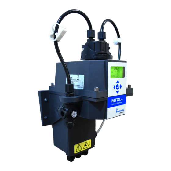
1.0 Overview Backpressure valve Shutoff Clamp Display USB Slot Keypad Drain Water Inlet Junction Box The MTOL+ - Product Description The MTOL+ process turbidimeter allows for the measurement of the turbidity of process water on-line. The MTOL+ works by nephelometry; which means it measures reflected light at 90°... -
Page 11: The Display
1.2 The Display Figure 1 illustrates all the items that can appear on the display. • The upper row of the display is used for reporting the turbidity levels and to provide user guidance in the customer setting routine. • The lower row of the display is used to communicate error messages and provide useful guidance. -
Page 12: Vapor Purge
Vapor Purge • The MTOL+ is equipped with a continuous Vapor Purge system. • A replaceable desiccant pouch in the lower portion of the instrument dries the air. System heat is used to warm the air. A fan inside the instrument continuously circulates heated dry air around the optical well and the flow through cuvette. -
Page 13: Installation
3.0 Installation The MTOL+ must be mounted and installed in a suitable location, plumbed to the sample water source (section 3.34), and hard-wired to electrical power (section 3.4). Installation MUST be performed by qualified technicians, including licensed electricians, following all instructions, complying with all local, state, federal and other governmental requirements, and with all building and construction codes and standards. -
Page 14: Site Selection
Site Selection Choose a site that is accessible and well-lighted for use, servicing, repair or replacement by authorized personnel. • MTOL+ should be located and mounted within 2-3 meters (6 to10 ft) of the sampling point to ensure a quick response time. •... - Page 15 1. Using masking tape, affix the mounting template to the vertical surface of the selected mounting location and mark location for screws. • The MTOL+ is designed for vertical wall mounting. If wall mounting is not practical, the instrument can be mounted on any suitable vertical, flat surface.
- Page 16 • Within 2-3 meters (6 to10 ft) of the sampling point to ensure a quick response time. • Isolated from vibration, and not susceptible to freezing or temperature extremes. • Suitable vertical and flat surface that can support the product’s weight 5 kg (10lbs).
-
Page 17: Plumbing & Assembly
Plumbing & Assembly ONLY qualified personnel should perform plumbing connections following all instructions, complying with all local, state, federal and other governmental requirements, and with all building and construction codes and standards. MTOL+ requires very little head pressure to operate 6.9kPa (1 PSI). ... - Page 18 Flow Through Cuvette The flow through cuvette is rated for a flow of 100ml/min - 1liter/min. (0.026-0.26Gal/min). SHUTOFF CLAMP This clamp allows for shutting off the intake flow during BACKPRESSURE VALVE cuvette maintenance. Press This valve allows for an down to restrict water flow. adjustment to reduce bubble formation.
-
Page 19: Connecting The Drain
3.3.3 Connecting the drain: MTOL+ drain tubing MUST be routed to a suitable sanitary sewer drain. Wetted materials are not FDA approved. DO NOT return the drain sample or any water run through MTOL+ into the process stream or into any potable water supply. b. - Page 20 c. Using a sharp utility knife, cut the end of the tubing square. Remove any burrs or sharp edges before inserting into fitting. d. Place a piece of tape ½ inch from the end of the tube to indicate how far the tube should be inserted. e.
-
Page 21: Electrical Connections
Electrical Connections • MTOL+ is electrically powered. Installation MUST be performed by licensed electrician following all instructions and comply with all local, state, federal and other governmental requirements, and with all building and construction codes and standards for all electrical connections and for installation of electrical connections to and between the instrument and any peripheral devices. -
Page 22: Electrical Power Connection
• The connections are labeled within the terminal box and are self- descriptive (see Figure 5). • Plugs are inserted into the alarm and 4-20mA/RS-485 cable glands when shipped, to ensure a watertight seal. These plugs should be removed and discarded when cabling to either of these connections. -
Page 23: Terminal Block (P1) Connections
j. Make connections following all local, state, federal and other governmental requirements, and all building and construction codes and standards for all electrical connections. Earth or Ground wire must be connected to a terminal on the MTOL+ marked “G”. k. A strain relief strap is provided to reduce tension on the power terminals. - Page 24 b. RS-485/Modbus Connection • The RS-485 half-duplex (2-wire) digital interface operates with differential levels that are not susceptible to electrical interferences. Cable lengths up to 900 meters (3000 ft.) can be implemented. • The last device on each bus may require terminating with a 120-ohm resistor to eliminate signal reflection on the line.
-
Page 25: Closing The Junction Box
3.4.3 Closing the Junction Box. Maintain watertight seal. Always make sure that the Junction Box cover is firmly in place and securely closed. Water infiltration can create electric shock/electrocution hazard and will damage equipment. • Securely close the Junction Box by replacing the cover and all four cover screws. -
Page 26: Setup, Configuration And Calibration
4.0 Setup, Configuration and Calibration Prior to use for the first time, the supplied desiccant pouch will need to be installed. Refer to section 5.1 Replacing or Installing the Desiccant Pouch. The instrument is supplied from the factory calibrated for the 0- 100 NTU range and can be used right away. - Page 27 a. AUTO mode is the normal automatic operation. This is the default mode when power is applied or restored. The other three modes of operation are limited to 15 minutes with no key presses after which they will return to AUTO made operation. b.
- Page 28 • All reading outputs and alarms are held while in this mode of operation. Relay contacts and the 4-20mA will be frozen (held at the current state) while the instrument is in the configuration mode. While in the configuration mode, the instrument has a time-out feature that automatically returns the system operation to the AUTO mode after a fifteen (15) minute period.
-
Page 29: Configuring The Mtol
d. HOLD mode is intended for servicing the instrument and holds the outputs and alarms. During this mode, the 4-20mA and alarms are frozen. This mode can be used to ensure that no changes accidentally are made to the instrument. This mode will time out after 15 minutes and revert back to AUTO mode. -
Page 30: Configuring The 4-20Ma Output
4.2.1 Configuring the 4-20mA Output The 4mA can be set higher than the 20mA level to invert the output current is required. This may be required to control a dosing pump. See 4.2.13 to calibrate the 4-20mA output. Enable 4-20mA – Enable or Disable 4-20mA Output: Enter the CONFIG mode by pressing the buttons until the arrow beside... -
Page 31: Baud Rate
• 20MA is displayed on the lower row of the LCD display. Select the turbidity level to assign to the 20MA using the and buttons. • Once the desired level has been set, press the button to accept the ... -
Page 32: Modbus Address
• Press the button to accept the setting and move to the next menu or the button to exit and return to AUTO. 4.2.3 Modbus Address – Address Selection • Select the Modbus address of the MTOL+ from 1 to 255. For more information on Modbus refer to the Modbus Manuals Cat #29291. - Page 33 b. Alarm Set Point: The level at which an alarm activates is called the alarm set point. On the instrument, the alarm set point is designated as “S/P”. The setpoint is adjustable to any valid turbidity level over the range of the instrument in steps of 0.01 NTU. c.
- Page 34 • Once the desired set point has been set, press the button to accept it and move to the next menu. • Alarm 1 Delay Times: 1. Delay On: The following display will appear to allow you to select the number of seconds currently set for the “delay on” time.
-
Page 35: Offset
4.2.5 Offset – Offset Reading Adjustment • A reading offset can be made to allow for the MTOL+ to agree with another instrument if desired. • This range is limited to ± 1NTU. • For more information refer to section 4.3.6. To change the Offset: Enter the CONFIG mode by pressing the ... -
Page 36: Signal Averaging
Setting Security Code: With the security feature enabled (“ON”), press button. The screen shown in the illustration below will appear: • The 3 digit security code is set one digit at a time. Using the buttons, select each digit. The flashing digit is the number that is currently being adjusted. -
Page 37: Display Resolution
button to move to the next menu until RESP is displayed. • Press the • Use the buttons to select the setting for the speed of response desired. • Press the button to accept the setting and move to the next menu or the ... -
Page 38: Display Units
To adjust Backlight Brightness: Enter the CONFIG mode by pressing buttons until the arrow beside CONFIG is illuminated, then press the button. • Press the button to move to the next menu until BRT is displayed. •... -
Page 39: Modbus Parity & Modbus Stop Bits
button to move to the next menu until CLN is displayed. • Press the • Select On or OFF using the buttons. • Press the button to accept I the setting and move to the next menu or ... - Page 40 4mA Adjustment: • The first menu outputs a constant 4mA while allowing for a small amount of adjustment. This adjustment will allow the operator to make the MTOL+ agree with a PLC or SCADA system. The adjustment limits are ± 200 counts or about ±...
- Page 41 • Press the button to accept the setting and move to the next menu or the button to exit and return to AUTO. 4.2.14 Instrument ID – Instrument Unique Number Identification • This menu provides the instrument with a unique ID up to 4 digits. This ID can be used when logged data is downloaded.
-
Page 42: Download Logged Files
4.2.16 Download Logged Files – Select to Download • This menu is used to download CSV files to a flash drive. The selections are No download (NO), Calibration file only (CAL), All Files (ALL) or individual month (Jan, Feb…). Once the data stick is inserted into the ... - Page 43 Setting Day: Enter the CONFIG mode by pressing the buttons until the arrow beside CONFIG is illuminated, then press the button. • Press the button to move to the next menu until DAY is displayed, then ...
- Page 44 • When the desired hour has been selected, press the button to accept it and move to the next menu or the button to exit and return to AUTO. Setting Minute: Enter the CONFIG mode by pressing the ...
-
Page 45: Update Software
4.2.18 Update Software - Install Latest Software or Change Range • Enter the CONFIG mode by pressing the buttons until the arrow beside CONFIG is illuminated, then press the button. • Press the button to move to the next menu until UPDT is displayed, ... -
Page 46: Calibrating The Mtol+, Cal Mode
• If the MTOL+ finds a flash drive with a previous version of software it will show the word FILE. You will need an updated file on the flash drive. • Once installed the system will automatically turn off and restart. The entire process takes up to 90 seconds to complete. - Page 47 4.3.1 Calibration Standards (0-100 NTU range) • If the MTOL+ will be used over the entire range of .02 to 100 NTU a complete calibration as described below will be required, but you must retain the same calibration schedule as described above. •...
-
Page 48: Calibration Standards
4.3.2 Indexing Calibration Cuvettes To achieve the greatest accuracy, and account for normal scratches and aberrations in cuvette glass when calibrating, HF Scientific recommends indexing the cuvettes. Standards and standard kits purchased from HF Scientific are supplied with indexing rings. Complete instructions regarding how to index the cuvettes are included in the calibration kits. -
Page 49: Calibration Procedures
4.3.3 Calibration Procedures It is recommended that the measurement chamber is kept covered during the calibration period and that the flow through cuvette is replaced immediately after the calibration to prevent premature saturation of the desiccant. The 0-100 NTU range will be described below. If another range is selected the MTOL+ will prompt for appropriate standards during calibration. -
Page 50: Abort Calibration
12. When complete, the lower display will now change to show alternating 02 and , requesting the 0.02 NTU standard. 13. Insert the requested 0.02 NTU standard. Index the standard to the lowest value on the upper display. 14. -
Page 51: Instrument Offset
4.3.6 Instrument Offset • Refer to section 4.2.5 • It is possible to use an offset factor in the instrument rather than performing a physical calibration. • This procedure is not recommended in lieu of regular instrument calibration but it can be used to make the MTOL+ agree with another instrument. -
Page 52: Operation
The instrument will return to the AUTO mode with the offset mathematically added to the reading. 5.0 Operation Prior to use for the first time, the supplied desiccant pouch will need to be installed. Installing or Replacing the Desiccant Pouch The MTOL+ continuously checks the condition of the desiccant. -
Page 53: Starting The System
Figure 8: Installing the desiccant Once the bag is opened, install the desiccant pouch immediately to prevent premature degradation of the desiccant. Starting the System The following steps describe how to measure the turbidity of a sample using this instrument: 1. -
Page 54: Routine Measurement: Auto Mode
Routine Measurement: AUTO Mode After the instrument has warmed up and the instrument is operating in AUTO mode, readings will be updated (posted) once per second. These updates occur to the screen, Modbus, 4-20mA and can be logged internally to the instrument. These updates also affect the operation of the alarms. -
Page 55: Modbus Communication
• Some sample data is shown below. Alarm Date Time Reading Units Alarm 2 6/9/2017 16:01 0.024 6/9/2017 17:02 0.023 6/9/2017 17:03 0.022 6/9/2017 17:04 0.022 6/9/2017 17:05 0.02 6/9/2017 17:06 0.02 6/9/2017 17:07 0.022 • The file structure of the logged data will be in Year/Month/Day. At midnight of each day the current day’s file is closed and a new day’s file is opened. -
Page 56: Patented Ultrasonic Cleaning
Patented Ultrasonic Cleaning This feature is used to continuously clean the flow through the cuvette. It is not intended to clean cuvettes that are already dirty or replace manual cleaning entirely. See section 5.7 for instructions on cuvette cleaning. The system will increase the time between cleanings dramatically. Please note that the system requires the use of a special cuvette which is included with the instrument. - Page 57 If condensate forms on the cuvette, use the following procedure: 1. Shut off the flow with the provided ratcheting clamp. 2. Empty the water out of the cuvette to lower the cold mass. 3. If clean warm water is available it can be poured into the cuvette. 4.
-
Page 58: Cleaning The Flow Through Cuvette
• The Vapor Purge system can NOT remove large droplets of water, only residual moisture. For the Vapor Purge system to function properly, all instrument seals must be maintained and the desiccant pack must be in good condition (no DESC display). SENSOR (TOP VIEW) ULTRASONIC... -
Page 59: Replacing The Source Lamp
The cuvette can be replaced by first shutting off the flow using the provided shutoff clamp; unscrewing the old cuvette and replacing with a fresh clean one. Figure 11: Flow-Through Assembly Replacing the Source Lamp The source lamps in the MTOL+ instruments are designed for long life. The IR lamp and white light version have long lives. -
Page 60: Troubleshooting
6.0 Troubleshooting 6.1 MTOL+ Fault Detection The MTOL+ performs continuous diagnostic monitoring. In the MTOL+ there are three levels of fault detection: 1. Warnings 2. Errors 3. Failures Any faults are displayed in a queue form in the bottom row of the LCD. How these faults are indicated depends on the settings made in sections 4.2.1 Configuring the Error Level and 4.2.4 Configuring the Alarms. -
Page 61: Diagnostic Table
Diagnostic Table Symptom Cause Cure Lower display shows MA 4-20 mA loop open Check wiring. See sections 3.4.2 and 4.2.1 Lower display shows DESC Desiccant pouch bad Change desiccant pouch. See section 5.1 Lower display shows LAMP Lamp failed Replace lamp. -
Page 62: Bubbles In The Sample
Bubbles in the Sample If bubbles are present in the sample water the readings may appear higher than expected. These reading may also not be stable. Remove cuvette if air can be seen coming into the flow-through unit from the inlet tube, this is air introduced, probably from a small water or air leak. This will need to be resolved in the plumbing. -
Page 63: Accessories And Replacement Parts List
7.0 Accessories and Replacement Parts List The items shown below are recommended accessories and replacement parts. Accessory Cat. # Photo Electronic Service Module For MTOL+ White Light, factory set to 0-100 NTU 02853 Electronic Service Module For MTOL+ 02852 Light, factory set to 0-100 NTU Replacement Lamp Assembly White Light 24082S Replacement Lamp Assembly IR Light... - Page 64 Formazine Stock Kit 50040 Formazine Stock Solution, 4000 NTU, 500 ml 70914 Replacement Desiccant Pouch 21555R Pressure Regulator 24306S Replacement Cuvette – for operation without 50036 cleaning (3 pack) Replacement Cuvette with Ultrasonic Transducer 24166S Tubing Kit Containing: 1-shutoff clamp, 1-backpressure valve, 2-connecting tubing with fittings for flow through 21062 assembly.
-
Page 65: Limited Warranty
8.0 Limited Warranty HF scientific, LLC (the “Company”) warrants each municipal market instrument product to be free from defects in material and workmanship under normal usage for a period of one (1) year from first use or two (2) years from date of the Company’s invoice from the original sale of the product, whichever occurs first. - Page 66 Catalog No. 29290 Rev 3 06/2020...
Need help?
Do you have a question about the HF scientific 28052 and is the answer not in the manual?
Questions and answers