Table of Contents
Advertisement
Quick Links
Instructions for Operation and Maintenance
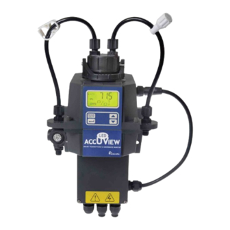
AccUView LED
UV Transmittance and Absorbance Monitor
IS-HF-AccUViewLED 2239
WARNING
!
Read this Manual BEFORE using this equipment.
Failure to read and follow all safety and use information can
result in death, serious personal injury, property damage, or
damage to the equipment.
Keep this Manual for future reference.
IS-HF-AccUViewLED
Advertisement
Table of Contents

Subscribe to Our Youtube Channel
Related Manuals for Watts HF Scientific AccUView LED


Summary of Contents for Watts HF Scientific AccUView LED
- Page 1 IS-HF-AccUViewLED Instructions for Operation and Maintenance AccUView LED UV Transmittance and Absorbance Monitor WARNING Read this Manual BEFORE using this equipment. Failure to read and follow all safety and use information can result in death, serious personal injury, property damage, or damage to the equipment.
- Page 2 DECLARATION OF CONFORMITY Application of Council Directive Standards to Which Conformity is Declared: Product Safety – Tested and passed: Part 1: General Requirements UL61010-1 Issued May 11 2012 Ed 3 and CAN/CSA C22.2 #61010-1 issued May 11 2012 Conforms to UL STD 61010-1 Certified to CSA STD C22.2 No.
-
Page 3: Table Of Contents
Table of Contents 1.0 Understanding Safety Information ..........4 7.4 Configuring the Alarms ............11 7.4.1 Alarm 1 ................12 1.1 Symbols Used in this manual ............4 7.4.2 Alarm 2 ................12 2.0 Introduction to the Unit ..............4 2.1 Overview...................4 7.5 Enabling the Security Access ..........12 7.6 Extended Settings ..............12 2.2 Specifications ................4 7.7 Units ..................12... -
Page 4: Understanding Safety Information
1.0 Understanding Safety 2.0 Introduction to the Unit Information 2.1 Overview This manual contains basic instructions that must be followed during The AccUView LED process transmittance monitor allows for the UV the commissioning, operation, care and maintenance of the instrument. transmittance or absorbance measurement of process water on-line. -
Page 5: Display
3.0 Installation and Commissioning 2.4 Display Figure 1 illustrates all the items that can appear on the display. The Prior to use for the first time, the supplied desiccant pouch upper row of the display (1) is used for reporting the % T levels and to will need to be installed. -
Page 6: Plumbing
3.2 Plumbing The recommended plumbing for the instrument is shown in Figure 4. NOTICE The instrument is designed to require very little head pressure to operate; Model 28042 is equipped with a flow switch. For this instrument around 6.9kPa (1 PSI). Flow requirements are 100ml/min. – 1.5 liter/min. the user connections are equipped with ¼"... -
Page 7: Electrical Connections
3.3 Electrical Connections All of the electrical connections to the instrument are made through the It is the user’s responsibility to assure that the watertight seal is maintained field terminal box, which should be located directly under the sensor after the terminal box has been wired for operation. If any of the bulkheads portion of the instrument. -
Page 8: Operation
4.0 Operation 4.3 Security Access Feature This process monitor allows for the measurement of the transmittance of process water on-line. Process water is usually reported in units The instrument is equipped with a security access code feature that can of %T. Readings above 102 %T are indicated by a flashing display. be activated in the configuration mode. -
Page 9: Instrument Calibration
5.0 Instrument Calibration 5.2 ABS Calibration The instrument was calibrated and tested prior to leaving the factory. Therefore, it is possible to use the instrument directly out of the box. Under normal conditions, re-calibration is recommended at least once NOTICE every month. -
Page 10: Calibration Error
7.0 Instrument Configuration 5.3 Calibration Error (CONFIG mode) If the screen shown below is displayed after the 100%T or 0 ABS calibration, the internal diagnostics have determined that the calibration fluid requires replacement or the flow through cuvette requires The instrument has been designed to provide the ability to customize replacement. -
Page 11: Setting The 20 Ma Level
7.2.2 Setting the 20 mA Level 7.3.2 Setting the Address The next, prompt will be the %T or ABS level assigned to the 20 mA The last selection is the address. This Address is important where multiple output level (20MA) on the lower row of the LCD display). Select the %T instruments are wired on a single string. -
Page 12: Alarm 1
7.4.1 Alarm 1 7.6 Extended Settings Alarm 1 Function: The ALM1 is displayed and the display indicates the current function of alarm 1 (HI, LO, OFF or Error). Use the or buttons to cycle through and select the desired function. Press the button to accept the selection. -
Page 13: Ultrasonic Cleaning
7.10 Ultrasonic Cleaning 7.14 Duty Cycle This allows for a selection menu to turn OFF the ultrasonic cleaning This determines how often the lamp turns on and updates the reading. function if desired. The default mode is On. Make a selection using the The lamp will operate for 1 second each time to obtain readings. -
Page 14: Ma Adjustment
8.0 Additional Features and 7.17 20mA Adjustment Options 8.1 Backlit LCD The backlit LCD allows for easier readability of the LCD display in low light or no light conditions. The backlight is intended for continuous operation. The brightness is adjustable from a menu in the CONFIG mode. 8.2 Ultrasonic Cleaning This menu operates similar to the previous menu. -
Page 15: Simple Communication
9.0 Routine Maintenance 8.3.2 Simple Communication The AccUView LED can provide basic communications over simple programs such as the Hilgraeve HyperTerminal that is included with 9.1 Cleaning the Flow Through Cuvette most Microsoft Windows packages. The user could also use Visual Basic or other programs. -
Page 16: Troubleshooting
10.0 Troubleshooting 10.1 AccUView LED Fault Detection 10.3 Diagnostic Chart The AccUView LED performs continuous diagnostic monitoring. In the Symptom Cause Cure AccUView LED there are three levels of fault detection; warnings, errors and failures. Any faults are displayed in a queue form in the bottom row Lower display shows MA 4-20 mA loop open Check wiring. -
Page 17: Accessories And Replacement Parts List
11.0 Accessories and Replacement Parts List The items shown below are recommended accessories and replacement parts. Accessory Catalog Number Replacement Desiccant Pouch 21555R 100 % T Calibration Solution - 500 ml 19323 Replacement Electronics Service Module Contact Factory Replacement Quartz Cuvette with Ultrasonic Transducer 24232S Operating Manual, AccUView LED 29173... - Page 18 Mounting Template All dimensions are in millimeters (inches) 50.80 (2.000) 90.17 (3.500) 87.33 (3.438) 30.17 (1.188) 147.66 (5.813) Note: 1) See the mounting instructions in the manual for mounting hardware sizes. 2) Provide at least 200mm (8 inches) of free space above the sensor for easy removal of the flow head and insertion of the calibration standards.
- Page 19 Notes _ _ _ _ _ _ _ _ _ _ _ _ _ _ _ _ _ _ _ _ _ _ _ _ _ _ _ _ _ _ _ _ _ _ _ _ _ _ _ _ _ _ _ _ _ _ _ _ _ _ _ _ _ _ _ _ _ _ _ _ _ _ _ _ _ _ _ _ _ _ _ _ _ _ _ _ _ _ _ _ _ _ _ _ _ _ _ _ _ _ _ _ _ _ _ _ _ _ _ _ _ _ _ _ _ _ _ _ _ _ _ _ _ _ _ _ _ _ _ _ _ _ _ _ _ _ _ _ _ _ _ _ _ _ _ _ _ _ _ _ _ _ _ _ _ _ _ _ _ _ _ _ _ _ _ _ _ _ _ _ _ _ _ _ _ _ _ _ _ _ _ _ _ _ _ _ _ _ _ _ _ _ _ _ _ _ _ _ _ _ _ _ _ _ _ _ _ _ _ _ _ _ _ _ _ _ _ _ _ _ _ _ _ _ _ _ _ _ _ _ _ _ _ _ _ _ _ _ _ _ _ _ _ _ _ _ _ _ _ _ _ _ _ _ _ _ _ _ _ _ _ _ _ _ _ _ _ _ _ _ _ _ _ _ _ _ _ _ _ _ _ _ _ _ _ _ _ _ _ _ _ _ _ _ _ _ _ _ _ _ _ _ _ _ _ _ _ _ _ _ _ _ _ _ _ _ _ _ _ _ _ _ _ _ _ _ _ _ _ _ _ _ _ _ _ _ _ _ _ _ _ _ _ _ _ _ _ _ _ _ _ _ _ _ _ _ _ _ _ _ _ _ _ _ _ _ _ _ _ _ _ _ _ _ _ _ _ _ _ _ _ _ _ _ _ _ _ _ _ _ _ _ _ _ _ _ _ _ _ _ _ _ _ _ _ _ _ _ _ _ _ _ _ _ _ _ _ _ _ _ _ _ _ _ _ _ _ _ _ _ _ _ _ _ _ _ _ _ _ _ _ _ _ _ _ _ _ _ _ _ _ _ _ _ _ _ _ _ _ _ _ _ _ _ _ _ _ _ _ _ _ _ _ _ _ _ _ _ _ _ _ _ _ _ _ _ _ _ _ _ _ _ _ _ _ _ _ _ _ _ _ _ _ _ _ _ _ _ _ _ _ _ _ _ _ _ _ _ _ _ _ _ _ _ _ _ _ _ _ _ _ _ _ _ _ _ _ _ _ _ _ _ _ _ _ _ _ _ _ _ _ _ _ _ _ _ _ _ _ _ _ _ _ _ _ _ _ _ _ _ _ _ _ _ _ _ _ _ _ _ _ _ _ _ _ _ _ _ _ _ _ _ _ _ _ _ _ _ _ _ _ _ _ _ _ _ _ _ _ _ _ _ _ _ _ _ _ _ _ _ _ _ _ _ _ _ _ _ _ _ _ _ _ _ _ _ _ _ _ _ _ _ _ _ _ _ _ _ _ _ _ _ _ _ _ _ _ _ _ _ _ _ _ _ _ _ _ _ _ _ _ _ _ _ _ _ _ _ _ _ _ _ _ _ _ _ _ _ _ _ _ _ _ _ _ _ _ _ _ _ _ _ _ _ _ _ _ _ _ _ _ _ _ _ _ _ _ _ _ _ _ _ _ _ _ _ _ _ _ _ _ _ _ _ _ _ _ _ _ _ _ _ _ _ _ _ _ _ _ _ _ _ _ _ _ _ _ _ _ _ _ _ _ _ _ _ _ _ _ _ _ _ _ _ _ _ _ _ _ _ _ _ _ _ _ _ _ _ _ _ _ _ _ _ _ _ _ _ _ _ _ _ _ _ _ _ _ _ _ _ _ _ _ _ _ _ _ _ _ _ _ _ _ _ _ _ _ _ _ _ _ _ _ _...
-
Page 20: Warranty
12.0 Warranty Watts Regulator Co. (the “Company”) warrants each municipal market instrument product to be free from defects in material and workmanship under normal usage for a period of one (1) year from first use or two (2) years from date of the Company’s invoice from the original sale of the product, whichever occurs first.
Need help?
Do you have a question about the HF Scientific AccUView LED and is the answer not in the manual?
Questions and answers