BINMASTER CNCR-120 Operating Instructions Manual
Radar sensor for continuous level measurement of liquids
Hide thumbs
Also See for CNCR-120:
- Operating instructions manual (20 pages) ,
- Operating instructions manual (20 pages)
Table of Contents

Related Manuals for BINMASTER CNCR-120


Summary of Contents for BINMASTER CNCR-120
- Page 1 Operating Instructions Radar sensor for continuous level measurement of liquids CNCR-120 Modbus and Levelmaster protocol CNCR-130 Modbus and Levelmaster protocol Document ID: 925-0394 Rev C CNCR-120/130 • Modbus and Levelmaster protocol...
-
Page 2: Table Of Contents
8.2 Status messages ......................15 Removal ..........................17 9.1 Disposal ......................... 17 Certificates and approvals ....................17 10.1 Radio licenses......................17 Supplement .......................... 17 11.1 Technical data ......................17 11.2 Dimensions........................19 CNCR-120/130 • Modbus and Levelmaster protocol... -
Page 3: About This Document
Required personal protective equipment must always be worn when working on or with the device. 2.2 Appropriate use CNCR-130 is a sensor for continuous level measurement. Operational reliability is ensured only if the instrument is properly used according to the specifications in the operating instructions. CNCR-120/130 • Modbus and Levelmaster protocol... -
Page 4: Warning About Incorrect Use
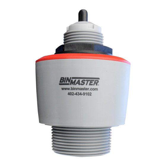
1 Radar antenna 3 Process fitting 3 Electronics housing 4 Mounting thread 5 Counter nut 6 Connection cable Fig. 2: Components of CNCR-130 1 Radar antenna 2 Process fitting 3 Electronics housing 4. Cable Outlet CNCR-120/130 • Modbus and Levelmaster protocol... -
Page 5: Principle Of Operation
• Smartphone/tablet (iOS or Android operating system) • PC/notebook with Bluetooth USB adapter (Windows operating system) Fig. 3: Wireless connection to standard operating devices with integrated Bluetooth LE 1 Sensor 2 Smartphone/Tablet 3 PC/Notebook CNCR-120/130 • Modbus and Levelmaster protocol... -
Page 6: Mounting
A ceiling mounting bracket is a simple method of mounting the sensor. Take note of Figure 5 for the recommended minimum distance to the vessel wall. The simplest mounting of the device is on the ceiling. Fig. 5: Ceiling mounting CNCR-120/130 • Modbus and Levelmaster protocol... -
Page 7: Mounting Instructions
For the wall mounting, a mounting bracket with a 1.5” opening from BinMaster is recommended. The sensor is secured in the mount using a 1.5” plastic counter nut. Take note of Figure 5 for the recommended minimum distance to the vessel wall. - Page 8 Fig. 8: Mounting of the radar sensor on round vessel tops In vessels with cone bottoms, the sensor can be mounted in the center of the vessel to measure material down to the outlet. Fig. 9: Mounting the radar sensor with conical bottom CNCR-120/130 • Modbus and Levelmaster protocol...
- Page 9 For socket or stand pipe mount, the pipe should be as short as possible and its end rounded to reduce false reflections from the end of the pipe. When using a threaded coupling, the antenna end should protrude at least 5 mm (0.2 in) out of the coupling. Fig. 12: Mounting the radar sensor with stand pipes CNCR-120/130 • Modbus and Levelmaster protocol...
- Page 10 The sensor should be mounted in a location where the radar signal is not interfered with by structure, such as ladders, braces or fill stream. Make sure when planning the installation there is a clear, unobstructed view to the material to be measured. After installation, a false signal suppression should be carried out to minimize any reflections from the mount or nearby structure. CNCR-120/130 • Modbus and Levelmaster protocol...
-
Page 11: Connecting To Power Supply
We recommend to connect the cable shield to ground at one end on the supply side when using shielded cable. 5.2 Wiring plan Fig. 14: Wire assignment in permanently connected connection cable CNCR-120/130 • Modbus and Levelmaster protocol... -
Page 12: Setup With Smartphone/Tablet (Bluetooth)
• Bluetooth 4.0 LE or newer Download the Wireless Device Configurator app from the “Apple App Store” or “Google Play Store” to your smartphone or tablet. To enable the Bluetooth software enter the BinMaster company ID code BMYQXZ. 6.2 Connecting Start the adjustment app and select the function “Setup”. The smart-phone/tablet searches automatically for Bluetooth-capable instruments in the area. -
Page 13: Parameter Adjustment
The selected menu item can be recognized by the color change. Fig. 16: Example of an app view - Setup sensor adjustment Enter the requested parameters and confirm via the keyboard or the editing field. The settings are then active in the sensor. Close the app to terminate connection. CNCR-120/130 • Modbus and Levelmaster protocol... -
Page 14: Menu Overview
False signal suppression False signal suppression Sounded distance to the material Reset Delivery status, basic settings Status Sensor status Measured value status Status output Status additional measured values Echo Curve Indication of echo curve CNCR-120/130 • Modbus and Levelmaster protocol... -
Page 15: Diagnostics And Servicing
Error during setup Repeat setup Error in the instrument False signal suppression faulty Reset instrument settings Error when carrying out a reset F265 Program sequence of the Device restarts automatically measuring function disturbed Measurement function disturbed CNCR-120/130 • Modbus and Levelmaster protocol... - Page 16 Carry out reset and repeat setup Error in the instrument Error when carrying out a reset settings False signal suppression faulty M508 Data error in program memory Bluetooth controller M509 Software update M510 No communication with the sensor CNCR-120/130 • Modbus and Levelmaster protocol...
-
Page 17: Removal
Materials, non-wetted parts – Housing PVDF – Cable entry seal – Connection cable Weight – Instrument 0.7 kg (1.543 lbs) – Connection cable 0.1 kg/m Process fitting Thread G1½, R1½, 1½ NPT Mounting connection Thread G1, R1, 1 NPT CNCR-120/130 • Modbus and Levelmaster protocol... - Page 18 -40 to +80 °C (-40 to +176 °F) Process conditions For the process conditions, please also note the specifications on the printed label. The lowest value (amount) always applies. Process temperature -40 to +80 °C (-40 to +176 °F) Process pressure -1 to 3 bar (-100 to 200 kPa/-14.5 to 43.51 psig) CNCR-120/130 • Modbus and Levelmaster protocol...
-
Page 19: Dimensions
(4 bytes) according to IEEE 754 are transmitted with individually selectable order of the data bytes (byte transmission order). This “Byte transmission order” is determined in the parameter “Format Code”. Hence the RTU knows the registers of the CNCR-130 which must be contacted for the variables and status information. CNCR-120/130 • Modbus and Levelmaster protocol... - Page 20 In case of more than one sensor, the wild card must not be used, because otherwise several slaves will answer • Commands that modify the instrument return the command with “OK“. “EE-ERROR” replaces “OK” if there was a problem changing the configuration CNCR-120/130 • Modbus and Levelmaster protocol...
- Page 21 Set number of Floats Parameter Length Code/Data Request: Set number of Floats 5 characters ASCII UuuFn Response: Set number of Floats 6 characters ASCII UuuFOK If the number is set to 0, no level is returned CNCR-120/130 • Modbus and Levelmaster protocol...
- Page 22 (50 up to 250), default = 127 ms Error codes Error Code Name EE-Error Error While Storing Data in EEPROM FR-Error Erorr in Frame (too short, too long, wrong data) LV-Error Value out of limits CNCR-120/130 • Modbus and Levelmaster protocol...
- Page 23 Primary Variable in Byte Order of Register 3000 1304 Secondary Variable in Byte Order of Register 3000 1306 Third Variable in Byte Order of Register 3000 1308 Quarternary Variable in Byte Order of Register 3000 CNCR-120/130 • Modbus and Levelmaster protocol...
- Page 24 Quarternary Variable in Byte Order BACD (Middle Endian) Unit Codes for Register 104, 108, 112, 116 Unit Code Measurement Unit Degree Celsius Degree Fahrenheit US Gallon Liters Imperial Gallons Cubic Meters Feet Meters Barrels CNCR-120/130 • Modbus and Levelmaster protocol...
- Page 25 This function code is used to write to a single Holding Register. Parameter Length Code/Data Request: Function Code 1 Byte 0x06 Start Address 2 Bytes 0x0000 to 0xFFFF Number of Registers 2 Bytes Data CNCR-120/130 • Modbus and Levelmaster protocol...
- Page 26 2 Bytes 0x0001 to 0x007B Byte Number 1 Byte Register Value N*2 Bytes Data Response: Function Code 1 Byte 0x10 Sub Function Code 2 Bytes 0x0000 to 0xFFFF Data 2 Bytes 0x01 to 0x7B CNCR-120/130 • Modbus and Levelmaster protocol...
- Page 27 Next Object ID 1 Byte Object ID number Number of Objects 1 Byte List of Object ID 1 Byte List of Object length 1 Byte List of Object value 1 Byte Depending on the Object ID CNCR-120/130 • Modbus and Levelmaster protocol...
- Page 28 The basic number of the input registers is always added to the input register address of CNCR-130. This results in the following constellations: • Fisher ROC 809 - Register address for 1300 is address 1300 CNCR-120/130 • Modbus and Levelmaster protocol...
- Page 29 • ScadaPack - Register address for 1302 is address 31303 11.7 Dimensions CNCR-120 Fig. 19: Dimensions CNCR-120 1 Thread G1½ 2 Thread 1½ NPT 3 Thread R1½ CNCR-130 Fig. 20: Dimensions CNCR-130 1 Thread G1½ 2 Thread 1½ NPT 3 Thread R1½ CNCR-120/130 • Modbus and Levelmaster protocol...
- Page 30 Subject to change without prior notice. BinMaster Phone: 402-434-9102 7201 N 98th St. Fax: 402-434-9133 Lincoln NE 68507 E-mail: info@binmaster.com www.binmaster.com CNCR-120/130 • Modbus and Levelmaster protocol...
Need help?
Do you have a question about the CNCR-120 and is the answer not in the manual?
Questions and answers