
Subscribe to Our Youtube Channel
Related Manuals for BINMASTER CNCR-190


Summary of Contents for BINMASTER CNCR-190
- Page 1 Operating Instructions Radar sensor for continuous level measurement of liquids CNCR-190 Two-wire 4-20 mA/HART Document ID: 925-0398 Rev B CNCR-190 • Two-wire 4-20 mA/HART...
-
Page 2: Table Of Contents
8.1 Maintenance ........................14 8.2 Status messages ......................14 Removal ..........................16 9.1 Disposal ......................... 16 Certificates and approvals ....................16 10.1 Radio licenses......................16 Supplement .......................... 17 11.1 Technical data ......................17 11.2 Dimensions........................19 CNCR-190 • Two-wire 4-20 mA/HART... -
Page 3: About This Document
Required personal protective equipment must always be worn when working on or with the device. 2.2 Appropriate use CNCR-190 is a sensor for continuous level measurement. Operational reliability is ensured only if the instrument is properly used according to the specifications in the operating instructions. 2.3 Warning about incorrect use Inappropriate or incorrect use of this product can result in application specific hazards, e.g. vessel... -
Page 4: Product Description
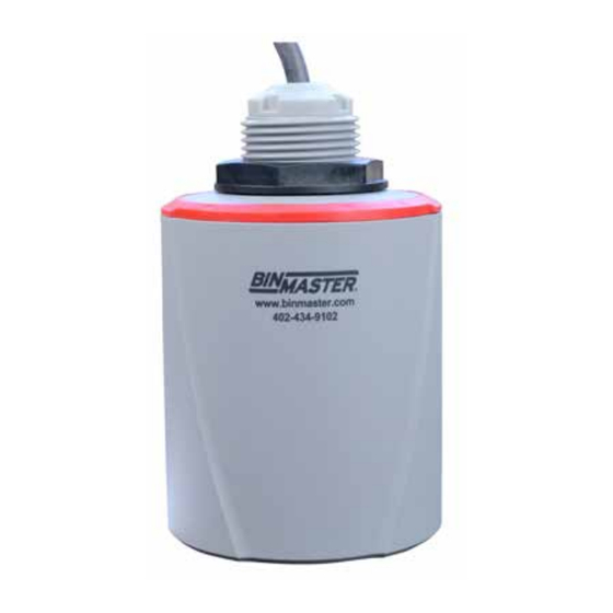
4. Locking nut 5. Connection cable 3.2 Principle of operation CNCR-190 is a radar sensor for continuous level measurement. It is suitable for liquids and solids in practically all industries. The instrument emits a continuous, frequency-modulated radar signal from its antenna. The emitted signal is reflected by the material and received by the antenna as an echo with a modified frequency. - Page 5 Fig. 3: Connecting the PC to the signal cable 1. Sensor 2. HART resistance 250 Ω (optional depending on evaluation) 3. Connection cable with 2 mm pins and terminals 4. Voltage supply 5. Interface adapter CNCR-190 • Two-wire 4-20 mA/HART...
-
Page 6: Mounting
The narrow portion of the radar signal is in the middle of the printed label on the instrument. This should be pointed towards the center of the vessel or any obstacle that may cause any unwanted reflection to minimize false echoes, for example the sidewall or vessel structure. CNCR-190 • Two-wire 4-20 mA/HART... - Page 7 Fig. 6: Mounting of the radar sensor on round vessel tops In vessels with cone bottoms, the sensor can be mounted in the center of the vessel to measure material down to the outlet. CNCR-190 • Two-wire 4-20 mA/HART...
- Page 8 The antenna edge of the device is the beginning of the measuring range and at the same time the reference plane for the min./max.adjustment, see following diagram: Fig. 8: Reference plane 1. Reference plane Do not mount the instruments in or above the fill stream. Make sure that it is pointed towards the material surface, not the fill stream. Fig. 9: Mounting of the radar sensor away from fill stream. CNCR-190 • Two-wire 4-20 mA/HART...
- Page 9 The antenna edge should protrude at least 5 mm (0.2 in) out of the socket or stand pipe. Fig. 10: Recommended socket mounting of CNCR-190 If the reflective properties of the material are good, you can mount the CNCR-190 on sockets or stand pipe longer than the antenna. The pipe end should be smooth, burr-free, and the end rounded.
-
Page 10: Connecting To Power Supply
Shielded cable generally necessary in HART multidrop mode. We recommend to connect the cable screening to ground potential at one end on the supply side when using shielded cable. 5.2 Wiring plan Fig. 12: Wire assignment in permanently connected connection cable CNCR-190 • Two-wire 4-20 mA/HART... -
Page 11: Setup With Smartphone/Tablet (Bluetooth)
• Operating system: Android 5.1 or newer • Bluetooth 4.0 LE or newer Download the Wireless Device Configurator app from the “Apple App Store” or “Google Play Store” to your smartphone or tablet. To enable the Bluetooth software enter the BinMaster company ID code BMYQXZ. 6.2 Connecting Start the adjustment app and select the function “Setup”. The smartphone/tablet searches automatically for Bluetooth-capable instruments in the area. -
Page 12: Parameter Adjustment
Close the app to terminate connection. Note: If the CNCR fails to connect to the Wireless Device Configuration App (WDCA) via Bluetooth, close the (WDCA), power cycle the CNCR and attempt to reconnect. If further action is required, power cycle the Bluetooth on your device, and repeat the steps above. CNCR-190 • Two-wire 4-20 mA/HART... -
Page 13: Menu Overview
Lin. percent Second HART value (SV) Distance Third HART value (TV) Measurement reliability Fourth HART value (QV) Electronics temperature Long TAG Message Reset Delivery status, basic settings Status signals Function check Maintenance required Off Out of specification CNCR-190 • Two-wire 4-20 mA/HART... -
Page 14: Diagnostics And Servicing
Send instrument in for repair Bit 4 of Byte 0 Hardware error to 5 F080 General software error Restart instrument Byte 5, Byte 5, General software error Bit 5 of Byte 0 to 5 CNCR-190 • Two-wire 4-20 mA/HART... - Page 15 Byte 23, Bit 5 of further filling Overfilling Byte 14 to 24 Check level in the vessel S603 Terminal voltage too low Check terminal voltage, increase Byte 23, Bit 6 of Byte 14 to 24 operating voltage Impermissible operating voltage CNCR-190 • Two-wire 4-20 mA/HART...
-
Page 16: Removal
The device has been tested and approved in accordance with the current edition of the applicable country-specific norms or standards. Bluetooth The Bluetooth radio module in the device has been tested and approved according to the current edition of the applicable country-specific norms or standards. CNCR-190 • Two-wire 4-20 mA/HART... -
Page 17: Supplement
The measurement range is the distance between the antenna face of the sensor and the product surface. The antenna face is also the reference plane for the measurement. Fig. 15: Measurement Range 1. Reference plane 2. Measured variable, max. measuring range CNCR-190 • Two-wire 4-20 mA/HART... - Page 18 9 to 35 V DC Reverse voltage protection Integrated Electrical protective measures Protection rating IP66/IP68 (3 bar) according to IEC 60529, Type 4P according to UL 50 Altitude above sea level 5000 m (16404 ft) Protection class Pollution degree CNCR-190 • Two-wire 4-20 mA/HART...
-
Page 19: Dimensions
11.2 Dimensions CNCR-190 Fig. 16: Dimensions CNCR-190 CNCR-190 • Two-wire 4-20 mA/HART... - Page 20 Subject to change without prior notice. BinMaster Phone: 402-434-9102 7201 N 98th St. Fax: 402-434-9133 Lincoln NE 68507 E-mail: info@binmaster.com www.binmaster.com CNCR-190 • Two-wire 4-20 mA/HART...
Need help?
Do you have a question about the CNCR-190 and is the answer not in the manual?
Questions and answers