
Subscribe to Our Youtube Channel
Related Manuals for BINMASTER CNCR-220


Summary of Contents for BINMASTER CNCR-220
- Page 1 Operating Instructions Radar sensor for continuous level measurement CNCR-210 Two-wire 4- 20 mA CNCR-220 Two-wire 4- 20 mA/HART Document ID: 925-0395 Rev C CNCR-210/220 • Two-wire 4-20...
-
Page 2: Table Of Contents
Contents About this document ......................3 For your safety ........................3 2.1 Authorized personnel ....................... 3 2.2 Appropriate use........................ 3 2.3 Warning about incorrect use .................... 4 Product description ....................... 4 3.1 Configuration........................4 3.2 Principle of operation ....................... 5 3.3 Adjustment ........................ -
Page 3: About This Document
About this document Information, note, tip: This symbol indicates helpful additional information and tips. Note: This symbol indicates notes to prevent failures, malfunctions, damage to devices or facility. Caution: Non-observance may result in personal injury. Warning: Non-observance may result in serious or fatal personal injury. Danger: Non-observance of the information marked with this symbol results in serious or fatal personal injury. -
Page 4: Warning About Incorrect Use
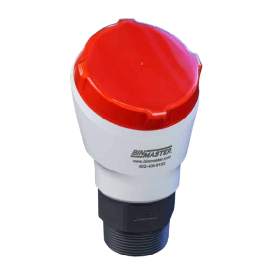
2.3 Warning about incorrect use Inappropriate or incorrect use of this product can result in application-specific hazards, e.g. vessel overfill by incorrect mounting or adjustment. Damage to property and persons or environmental contamination can result. Safety instructions for Ex areas Take note of the Ex specific safety instructions for Ex applications. These instructions are attached as documents to each instrument with Ex approval and are part of the operating instructions. 3 Product Description 3.1 Configuration Fig. 1: Components of CNCR-210/220 Radar antenna 2 Process fitting Process seal... -
Page 5: Principle Of Operation
3.2 Principle of operation CNCR-210/220 is a radar sensor for continuous level measurement. It is suitable for liquids and solids in practically all industries. The instrument emits a continuous, frequency-modulated radar signal from its antenna. The emit- ted signal is reflected by the material and received by the antenna as an echo with a modified frequency. The frequency change is proportional to the distance to the material. 3.3 Adjustment Devices with integrated Bluetooth module can be adjusted wirelessly via software adjustment tools: •... -
Page 6: Mounting
4 Mounting 4.1 General instructions The instrument is suitable for standard and extended ambient conditions according to DIN/EN/IEC/ ANSI/ISA/UL/CSA 61010-1. It can be used indoors as well as outdoors. Protect your instrument against moisture ingress through the following measures: • Use a suitable connection cable • Tighten the cable gland or plug connector firmly •... - Page 7 When mounting the sensor, distance it at least 200 mm (7.874 in) from the vessel wall. If the sensor is installed in the center of dished or round vessel tops, multiple echoes can arise. However, these can be suppressed by a false signal suppression (see chapter “Setup”). If you cannot maintain this distance, you should carry out a false signal suppression during initial setup.
- Page 8 The lower side of the radar antenna is the reference plane for the min./max. adjustment, see following diagram: Fig. 6: Reference plane 1 Reference plane Do not mount the instrument in or above the fill stream. Make sure that it is pointed towards the material surface, not the fill stream. Fig. 7: Mounting the radar sensor with inflowing material For socket or stand pipe mount, the pipe should be as short as possible and its bottom end rounded to reduce false reflections from the end of the pipe.
-
Page 9: Connecting To Power Supply
If the reflective properties of the material are good, you can mount the CNCR-210 on sockets or stand pipes longer than the antenna. The pipe end should be smooth, burr-free and the end rounded. Note: When mounting on longer sockets, we recommend carrying out a false signal suppression after install (see chapter “Parameter adjustment”). Recommended values for socket or stand pipe lengths and heights are in the following table. The values come from typical applications. -
Page 10: Connecting
Warning: Only connect or disconnect in de-energized state. Note: Power the instrument via an energy-limited circuit (power max. 100 W) according to IEC 61010-1, e.g. • Class 2 power supply unit (acc. to UL1310) • SELV power supply unit (safety extra-low voltage) with suitable internal or external limitation of the output current Use round cable to ensure effective sealing of the cable gland to the appropriate IP rating and check the cable diameter versus the cable gland before wiring for proper fit. -
Page 11: Wiring Plan
• Operating system: iOS 8 or newer • Operating system: Android 5.1 or newer • Bluetooth 4.0 LE or newer Download the Wireless Device Configurator app from the “Apple App Store” or “Google Play Store” to your smartphone or tablet. To enable the Bluetooth software enter the BinMaster company ID code BMYQXZ. CNCR-210/220 • Two-wire 4-20... -
Page 12: Connecting
6.2 Connecting Start the adjustment app and select the function “Setup”. The smartphone/tablet searches automatically for Bluetooth-capable instruments in the area. The message “Connecting …” is displayed. The devices found are listed and the search is automatically continued. Select the requested instrument in the device list. When establishing the connection for the first time, the operating tool and the sensor must authenticate each other. After the first correct authentication, each subsequent connection is made without a new authentication query. -
Page 13: Parameter Adjustment
6.3 Parameter adjustment The sensor adjustment menu is divided into two areas, which are arranged next to each other or one below the other, depending on the smartphone/tablet. • Navigation section • Menu item display The selected menu item can be recognized by the color change. Fig. -
Page 14: Menu Overview
Distance from sensor Min. adjustment (distance B) - 4mA (0%) Max. adjustment 0.0 m Min. adjustment 8.0 m Adjustment CNCR-220 Max. adjustment (distance A) - 20mA (100%) Distance from sensor Min. adjustment (distance B) - 4mA (0%) Max. adjustment 0.0 m Min. -
Page 15: Diagnostics And Servicing
8 Diagnostics and servicing 8.1 Maintenance If the device is used properly, no special maintenance is required in normal operation. In some applications, buildup on the antenna system can influence the measurement. Depending on the sensor and application, be careful to avoid heavy soiling of the antenna system. If necessary, clean the antenna system periodically. 8.2 Status messages The status messages are divided into the following categories: •... - Page 16 Failure Code DevSpec Text message Cause Rectification State in CMD 48 F113 EMC interference Remove EMC influences Byte 4, Bit 4 of Communication Byte 0-5 error F125 Temperature of the electronics Check ambient temperature Byte 5, Bit 7 of Impermissible electronics in the non-specified range Insulate electronics Byte 0-5 temperature...
-
Page 17: Removal
Maintenance Code DevSpec State in Text message Cause Rectification CMD 48 M500 The data could not be restored Repeat reset Byte 24, Bit 0 of Error during the during the reset to delivery Load XML file with sensor data Byte 14-24 reset “delivery status” status into the sensor M501 Hardware error EEPROM... -
Page 18: Supplement
CNCR-210 Max. measuring range 8 m (26.25 ft) Recommended measuring range up to 5 m (16.4 ft) CNCR-220 Max. measuring range 15 m (49.21 ft) Recommended measuring range up to 10 m (32.81 ft) CNCR-210/220 • Two-wire 4-20... - Page 19 Fig. 13: Measurement Range 1 Reference plane 2 Measured variable, max. measuring range Output Output signal 4 to 20 mA Range of the output signal 3.8 to 20.5 mA (default setting) Signal resolution 0.3 μA Resolution, digital 1 mm (0.039 in) Fault signal, current output (adjustable) ≤ 3.6 mA, >=21 mA, last valid measured value Max.
-
Page 20: Dimensions
Voltage supply Operating voltage UB – at 4 mA 12 to 35 V DC – at 20 mA 9 to 35 V DC Reverse voltage protection Integrated Electrical protective measures Altitude above sea level 5000 m (16404 ft) Protection class Pollution degree 11.2 Dimensions CNCR-210/220... - Page 21 Subject to change without prior notice. BinMaster Phone: 402-434-9102 7201 N 98th St. Fax: 402-434-9133 Lincoln NE 68507 E-mail: info@binmaster.com www.binmaster.com CNCR-210/220 • Two-wire 4-20...
Need help?
Do you have a question about the CNCR-220 and is the answer not in the manual?
Questions and answers