
Subscribe to Our Youtube Channel
Related Manuals for BINMASTER SmartBob AO


Summary of Contents for BINMASTER SmartBob AO
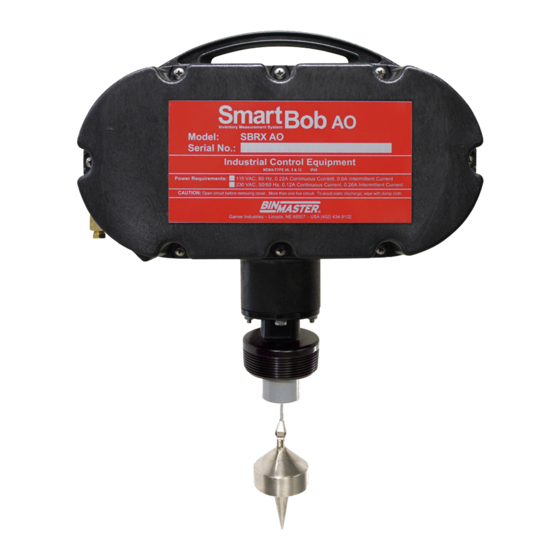
- Page 1 SmartBob AO BinMaster: Division of Garner Industries 7201 N. 98th St., Lincoln, NE 68507 402-434-9102 • email: info@binmaster.com www.binmaster.com OPERATING INSTRUCTIONS PLEASE READ CAREFULLY 925-0406 0613...
-
Page 2: Table Of Contents
TABLE OF CONTENTS Safety Summary ........................3 Introduction ..........................4 Specifications .......................... 5 Location and Mounting ......................6 Connections and Wiring ......................6 Power ..........................6 Start Input ........................7 Override Input ........................ 7 4-20 mA Output ......................8 Relay 1 and 2 Outputs....................9 Wiring Diagram ...................... -
Page 3: Safety Summary
Safety Summary Review the following safety precautions to avoid injury and prevent damage to the equipment. The product should be installed, commissioned, and maintained by qualified and authorized personnel only. Install according to installation instructions and comply with all National and Local codes. Use electrical wire that is sized and rated for the maximum voltage and current of the application. -
Page 4: Introduction
During a measurement, the SmartBob AO lowers a weighted probe and measures the distance by counting pulses from an internal encoder. When the SmartBob AO detects a lack of encoder pulses (detection of product), it reverses direction and retracts the probe. -
Page 5: Specifications
0.01 ft/m 4-20 mA Current Output Mode 1 (recommended) Isolated (3,750 Vrms surge), external power required Mode 2 Non-isolated, SmartBob AO powers the loop Max Loop Resistance (Mode 1) Depends on external power Max Loop Resistance (Mode 2) 500 ohms Accuracy 0.35%... -
Page 6: Location And Mounting
Location and Mounting The SmartBob AO should be mounted on the top of the storage vessel using a 3-inch NPT coupling and always in a vertical position. If a 3-inch NPT floor flange is used, it must be on a flat level surface to provide a vertical mount for the unit. -
Page 7: Start Input
Start Input This input is used to initiate a measurement and should only be connected to a normally open set of dry contacts, such as a relay or a push button switch. Momentarily closing the contacts connected to these terminals will be detected as a start signal and initiate a measurement. -
Page 8: 4-20 Ma Output
4-20 mA Output This output will provide a 4-20 mA output scale based on the user-set calibration points and the last measurement. It will also provide a 22 mA signal following an error condition or when no measure- ment has been taken. There are two modes available, which require the user to properly set jumpers on the printed circuit board and to properly wire to the correct terminals. -
Page 9: Relay 1 And 2 Outputs
Mode 2 does not provide electrical isolation, but does provide the DC power for the loop. Be sure not to provide external power when using this mode. To use Mode 2, first power down the SmartBob and locate the 4-20 OUT terminal block. Next, con- nect the positive wire of the 4-20 loop wiring to the middle terminal and the negative wire to the bottom terminal. -
Page 10: Wiring Diagram
There is a 2-pin terminal block available for connection to each relay output. These relays can switch low current signals and are not meant to power motors or high-wattage light bulbs. Be sure to read the voltage and current limitations in the Specification sections. An unshielded two-conductor cable between 14 and 20 AWG will work for a connection to this input. -
Page 11: Air Purge System
Air Purge System Located on the lower right side of each SmartBob AO is a 1/4” NPT air fitting. This fitting can be used to connect an external source of dry, clean air or noncombustible gas to the remote housing. By adding pressure to the remote housing that is slightly greater than that in the vessel, material and dust from the vessel is prevented from entering into the unit. -
Page 12: Run/Display Mode
• Stuck Bottom Setup Menu In order to operate the setup menu, the electrical side of the SmartBob AO must be opened. After operating the setup menu, be sure to properly close and seal the SmartBob AO. Press MENU to enter the setup menu. This is only accessible when not performing a measurement or other motor driven operation. - Page 13 It can range from 0.00 to 409.59 feet or 0.00 to 124.84 meters. The default is 0.00 feet. Maximum Drop Distance – This is the maximum distance the SmartBob AO will allow the bob to drop, which can range from 0.34 to 409.59 feet or 0.11 to 124.84 meters. The default is 60.00 feet.
-
Page 14: Calibrating The 4-20 Ma Output
Calibrating the 4-20 mA Output Considering the tank shown at right, if you wanted 20 mA to indicate full and 4 mA to indicate empty, then set the 4 mA drop distance to 6.00 feet and the 20 mA drop distance to 0.50 feet. Any measurement of 6.0 feet or more (empty) will drive the output to 4 mA, any measurement of 0.5 feet or... -
Page 15: Cable Replacement Instructions
Cable Replacement Instructions Before Starting Disconnect the power source. Remove the flat cover on the back of the remote housing. Cable Replacement 1. Remove the cable from the supply pulley by pressing the “CYCLE” button on the top of the PC board. While keeping the cable taut, pull on the cable as the cable spools off the pulley. - Page 16 Loading the Supply Pulley 1. Reconnect the power source. 2. If loading the supply pulley is necessary, pull the cable taut. Load supply pulley by pressing the UP button located on the circuit board. Pressing this button will start the supply pulley turning in a clockwise direction, with the cable winding over the top.
-
Page 17: Probe Options
B1 and B2 This stainless steel probe is designed for granular materials from 20 lb. per cubic foot and greater. This probe is shipped standard with every SmartBob AO. A 416 SS magnetic version is order code B2. This probe is a hollow inverted 4-inch cone made of stainless steel and is designed for bulk products with a density from 5 lb. - Page 18 B5 and B6 This probe is designed for granular material with a density from 20 lbs. per cubic foot and greater. This probe is a digestible bottle that is filled with 32 oz. of paraffin wax. The digestible bottle is made from an engineering plastic which will not damage the material handling auger in the unlikely event that the probe should become separated from the unit.
-
Page 19: Limiting Stainless Steel Cable
AO, so that the probe is not lowered into an airlock, screw conveyor, or any other area that the probe might become trapped in. The SmartBob AO is shipped with 90 feet of cable unless otherwise specified. Disregard these instructions if the unit was ordered with the exact amount of cable necessary for your vessel. -
Page 20: Mounting Options
Mounting Options Standard Flange Mount High Temperature Mount 925-0406 0613... -
Page 21: 5-1/8" Floor Flange Template
SMARTBOB REMOTE MOUNTING TEMPLATE 5 inch floor flange 925-0406 0613... -
Page 22: 7" Floor Flange Template
SMARTBOB REMOTE MOUNTING TEMPLATE 5 inch floor flange 925-0406 0613... -
Page 23: Suredrop Cable Release
SureDrop Cable Release System Assembly Instructions Assemble the SureDrop cable release system in the order as shown in the figure below. 1) Ball Stop 2) Round Crimp 3) Ball Stop 4) Round Crimp 5) Cap 6) Ball Stop 7) Oval Crimp 8) Thimble 9) Cable After all items are located as shown, compress...
Need help?
Do you have a question about the SmartBob AO and is the answer not in the manual?
Questions and answers