
Subscribe to Our Youtube Channel
Related Manuals for BINMASTER NCR-25


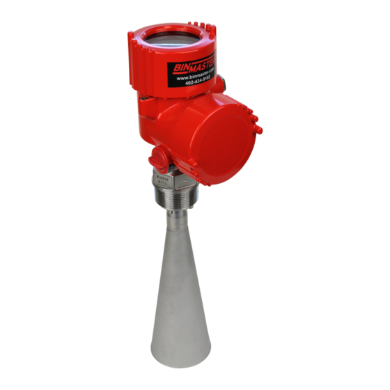
Summary of Contents for BINMASTER NCR-25
- Page 1 Operating Instructions Radar sensor for continuous level measurement of liquids NCR-25 4 … 20 mA/HART - two-wire 925-0369 Document ID: 36503 925-0369 Rev A...
-
Page 2: Table Of Contents
Measured value indication - Selection of national language ........... 43 Parameter adjustment ....................43 Saving the parameterisation data ................... 61 Setup with PACTware Connect the PC ......................62 Parameter adjustment ....................63 Saving the parameterisation data ................... 64 NCR-25 • 4 … 20 mA/HART - two-wire 925-0369 Rev A... - Page 3 Safety instructions for Ex areas Take note of the Ex specific safety instructions for Ex applications. These instructions are attached as documents to each instrument with Ex approval and are part of the operating instructions manual. Editing status: 2017-04-03 NCR-25 • 4 … 20 mA/HART - two-wire 925-0369 Rev A...
-
Page 4: About This Document
This arrow indicates a single action. Sequence of actions Numbers set in front indicate successive steps in a procedure. Battery disposal This symbol indicates special information about the disposal of bat- teries and accumulators. NCR-25 • 4 … 20 mA/HART - two-wire 925-0369 Rev A... -
Page 5: For Your Safety
C, K or W band range. The low emission power is far below the internationally approved limit values. When used correctly, the device poses no danger to health. NCR-25 • 4 … 20 mA/HART - two-wire 925-0369 Rev A... -
Page 6: Eu Conformity
The instrument must be permanently mounted on a closed vessel made of metal, reinforced concrete, or comparable attenuating materials • Flanges, process fittings and mounting accessories must ensure the microwave impermeability of the vessel and not let the radar signal escape to the outside NCR-25 • 4 … 20 mA/HART - two-wire 925-0369 Rev A... -
Page 7: Radio License For Usa
Operation is subject to the following conditions: • This device may not cause interference, and • This device must accept any interference, including interference that may cause undesired operation of the device NCR-25 • 4 … 20 mA/HART - two-wire 925-0369 Rev A... - Page 8 L’appareil ne doit pas produire de brouillage; et • L’utilisateur de l’appareil doit accepter tout brouillage radioélect- rique subi, même si le brouillage est susceptible d’en compromet- tre le fonctionnement. NCR-25 • 4 … 20 mA/HART - two-wire 925-0369 Rev A...
-
Page 9: Environmental Instructions
Directeur des Normes réglementaires d'Industrie Canada peut égale- ment être contacté). 2.10 Environmental instructions Protection of the environment is one of our most important duties. That is why we have introduced an environment management system NCR-25 • 4 … 20 mA/HART - two-wire 925-0369 Rev A... - Page 10 DIN EN ISO 14001. Please help us fulfil this obligation by observing the environmental instructions in this manual: • Chapter "Packaging, transport and storage" • Chapter "Disposal" NCR-25 • 4 … 20 mA/HART - two-wire 925-0369 Rev A...
-
Page 11: Product Description
Store" or the "Google Play Store" • Scan the Data Matrix code on the type label of the instrument or • Enter the serial number manually in the app NCR-25 • 4 … 20 mA/HART - two-wire 925-0369 Rev A... -
Page 12: Principle Of Operation
– Products with an ε value < 1.8, ≥1.5; applications with very bad reflective properties: Electronics with increased sensitivity The actual values that can be reached depend on the measurement conditions, the antenna system or the standpipe or bypass. NCR-25 • 4 … 20 mA/HART - two-wire 925-0369 Rev A... -
Page 13: Packaging, Transport And Storage
The integrated Bluetooth module (optional) enables wireless adjust- ment via standard adjustment devices: • Smartphone/tablet (iOS or Android operating system) • PC/notebook with Bluetooth USB adapter (Windows operating system) You can find further information in the operating instructions "Display and adjustment module PLICSCOM" (Document-ID 27835). NCR-25 • 4 … 20 mA/HART - two-wire 925-0369 Rev A... - Page 14 Protective cover The protective cover protects the sensor housing against soiling and intense heat from solar radiation. Bluetooth function with VEGADIS 82 can only be used at a later date. NCR-25 • 4 … 20 mA/HART - two-wire 925-0369 Rev A...
- Page 15 The antenna impedance cone is a replacement part used for optimum transmission of microwaves and for sealing against the process. You find further information in the operating instructions "Antenna impedance cone VEGAPULS 62 and 68" (Document-ID 31381). NCR-25 • 4 … 20 mA/HART - two-wire 925-0369 Rev A...
-
Page 16: Mounting
The free openings for the cable glands are therefore covered with red dust protection caps as transport protection. The dust protection caps do not provide sufficient protection against moisture. NCR-25 • 4 … 20 mA/HART - two-wire 925-0369 Rev A... -
Page 17: Mounting Preparations
A secure hold of the antenna is only ensured with the untwist guard. The untwist guards inserted on site must hence be used again. Depending on temperature range and antenna material, these are NCR-25 • 4 … 20 mA/HART - two-wire 925-0369 Rev A... - Page 18 On the version with rinsing air connection, make sure that the holes in the antenna and in the process fitting coincide. This ensures a suf- ficient air flow (the air is led through the holes to the feed system. A rinsing of the whole parabolic antenna is not intended). Fig. 3: Dismounting, parabolic antenna Connection piece Compression nut Counter nut Parabolic antenna NCR-25 • 4 … 20 mA/HART - two-wire 925-0369 Rev A...
-
Page 19: Mounting Instructions
Fig. 5: Mounting of the radar sensor on round vessel tops In vessels with conical bottom it can be advantageous to mount the sensor in the centre of the vessel, as measurement is then possible down to the bottom. NCR-25 • 4 … 20 mA/HART - two-wire 925-0369 Rev A... - Page 20 Mounting socket The socket piece should be dimensioned in such a way that the antenna end protrudes slightly out of the socket. Fig. 8: Recommended socket mounting with horn antenna NCR-25 • 4 … 20 mA/HART - two-wire 925-0369 Rev A...
- Page 21 Fig. 11: Distance between antenna and socket with parabolic antenna If the medium has good reflective properties, VEGAPULS 62 with horn antenna can also be mounted on a longer socket piece. Rec- ommended values for socket heights are specified in the following illustration. You must carry out a false signal suppression afterwards. NCR-25 • 4 … 20 mA/HART - two-wire 925-0369 Rev A...
- Page 22 Sensor orientation In liquids, direct the sensor as perpendicular as possible to the prod- uct surface to achieve optimum measurement results. Fig. 13: Alignment in liquids NCR-25 • 4 … 20 mA/HART - two-wire 925-0369 Rev A...
- Page 23 Small, inclined sheet metal baffles above the installations scatter the radar signals and prevent direct interfering reflections. Fig. 15: Cover flat, large-area profiles with deflectors Agitators If there are agitators in the vessel, a false signal suppression should be carried out with the agitators in motion. This ensures that the NCR-25 • 4 … 20 mA/HART - two-wire 925-0369 Rev A...
- Page 24 Information: The spacer may only be incorporated up to a maximum of 50 mm into the vessel insulation. Only then is a reliable temperature decoupling guaranteed. NCR-25 • 4 … 20 mA/HART - two-wire 925-0369 Rev A...
-
Page 25: Measurement Setup - Pipes
Under these prerequisites, the measurement of products with low dielectric values (ε value ≤ 1.6) is possible. Note the following illustrations and instructions for measurement in a surge pipe. Information: Measurement in a surge pipe is not recommended for extremely adhesive products. NCR-25 • 4 … 20 mA/HART - two-wire 925-0369 Rev A... - Page 26 100% Fig. 18: Configuration surge pipe VEGAPULS 62 Radar sensor Polarisation marking 3 Thread or flange on the instrument Vent hole Holes 6 Welding connection through U-profile Ball valve with complete opening Surge pipe end 9 Reflector sheet 10 Fastening of the surge pipe NCR-25 • 4 … 20 mA/HART - two-wire 925-0369 Rev A...
- Page 27 Preferably pultruded or straight beaded stainless steel tube • Welded joint should be straight and lie in one axis with the holes • Flanges are welded to the tube according to the orientation of the polarisation NCR-25 • 4 … 20 mA/HART - two-wire 925-0369 Rev A...
- Page 28 • An extension via welding neck flanges or pipe collars is not recom- mended. Measurement in the An alternative to measurement in a surge pipe is measurement in a bypass tube bypass tube outside of the vessel. NCR-25 • 4 … 20 mA/HART - two-wire 925-0369 Rev A...
- Page 29 • A false signal suppression with the installed sensor is recom- mended but not mandatory • The measurement through a ball valve with unrestricted channel is possible NCR-25 • 4 … 20 mA/HART - two-wire 925-0369 Rev A...
-
Page 30: Measurement Setup - Flow
In general, the following points must be observed: • Install the sensor on the headwater side • Installation in the centre of the flume and vertical to the liquid surface • Distance to the overfall orifice • Distance of orifice opening above ground • Min. distance of the orifice opening to tailwater • Min. distance of the sensor to max. storage level NCR-25 • 4 … 20 mA/HART - two-wire 925-0369 Rev A... - Page 31 In general, the following points must be observed: • Installation of the sensor at the inlet side • Installation in the centre of the flume and vertical to the liquid surface • Distance to the Venturi flume • Min. distance of the sensor to max. storage level NCR-25 • 4 … 20 mA/HART - two-wire 925-0369 Rev A...
-
Page 32: Connecting To Power Supply
The free openings for the cable glands are therefore covered with red dust protection caps as transport protection. NCR-25 • 4 … 20 mA/HART - two-wire 925-0369 Rev A... -
Page 33: Connecting
4. Remove approx. 10 cm (4 in) of the cable mantle, strip approx. 1 cm (0.4 in) of insulation from the ends of the individual wires 5. Insert the cable into the sensor through the cable entry NCR-25 • 4 … 20 mA/HART - two-wire 925-0369 Rev A... - Page 34 7. Check the hold of the wires in the terminals by lightly pulling on them 8. Connect the screen to the internal ground terminal, connect the external ground terminal to potential equalisation NCR-25 • 4 … 20 mA/HART - two-wire 925-0369 Rev A...
-
Page 35: Wiring Plan, Single Chamber Housing
Electronics compartment 4...20mA 6 7 8 Fig. 26: Electronics compartment - double chamber housing Internal connection to the terminal compartment For display and adjustment module or interface adapter NCR-25 • 4 … 20 mA/HART - two-wire 925-0369 Rev A... - Page 36 Ground terminal for connection of the cable screen Terminal compart- ment - Radio module PLICSMOBILE Status SIM-Card Test Fig. 28: Terminal compartment - Radio module PLICSMOBILE Voltage supply You can find detailed information on connection in the supplementary instructions "PLICSMOBILE GSM/GPRS radio module". NCR-25 • 4 … 20 mA/HART - two-wire 925-0369 Rev A...
-
Page 37: Wiring Plan, Ex-D-Ia Double Chamber Housing
Ground terminal for connection of the cable screen Plug M12 x 1 for external display and adjustment unit Fig. 31: Top view of the plug connector Pin 1 Pin 2 Pin 3 Pin 4 NCR-25 • 4 … 20 mA/HART - two-wire 925-0369 Rev A... -
Page 38: Double Chamber Housing With Vegadis-Adapter
Pin 2 Pin 3 Pin 4 Contact pin Colour, connection ca- Terminal, electronics ble in the sensor module Pin 1 Brown Pin 2 White Pin 3 Blue Pin 4 Black NCR-25 • 4 … 20 mA/HART - two-wire 925-0369 Rev A... -
Page 39: Wiring Plan - Version Ip 66/Ip 68, 1 Bar
As soon as a plausible measured value is found, the corresponding current is outputted to the signal cable. The value corresponds to the actual level as well as the settings already carried out, e.g. factory setting. NCR-25 • 4 … 20 mA/HART - two-wire 925-0369 Rev A... -
Page 40: Set Up With The Display And Adjustment Module
The display and adjustment module is powered by the sensor, an ad- ditional connection is not necessary. Fig. 35: Installing the display and adjustment module in the electronics compart- ment of the single chamber housing NCR-25 • 4 … 20 mA/HART - two-wire 925-0369 Rev A... -
Page 41: Adjustment System
Adjustment system Fig. 37: Display and adjustment elements LC display Adjustment keys • Key functions [OK] key: NCR-25 • 4 … 20 mA/HART - two-wire 925-0369 Rev A... - Page 42 (with inspection window) of the sensor housing. Fig. 38: Display and adjustment elements - with adjustment via magnetic pen LC display Magnetic pen Adjustment keys Bluetooth symbol Lid with inspection window NCR-25 • 4 … 20 mA/HART - two-wire 925-0369 Rev A...
-
Page 43: Measured Value Indication - Selection Of National Language
The parameter adjustment is carried out with an adjustment menu. Main menu The main menu is divided into five sections with the following func- tions: Setup: Settings, e.g., for measurement loop name, medium, applica- tion, vessel, adjustment, signal output NCR-25 • 4 … 20 mA/HART - two-wire 925-0369 Rev A... - Page 44 With bulk solids, the additional interfering fac- tors are dust generation, angle of repose and secondary echoes from the vessel wall. To adapt the sensor to these different measuring conditions, the selection "Liquid" or "Bulk solid" should be made in this menu item. NCR-25 • 4 … 20 mA/HART - two-wire 925-0369 Rev A...
- Page 45 • Transportable plastic tank • Open water (gauge measurement) • Open flume (flow measurement) • Rain water overfall (weir) Storage tank: • Setup: large-volumed, upright cylindrical, spherical • Medium speed: slow filling and emptying • Process/measurement conditions: NCR-25 • 4 … 20 mA/HART - two-wire 925-0369 Rev A...
- Page 46 – Large agitator blades of metal – Vortex breakers, heating spirals • Process/measurement conditions: – Condensation, buildup by movement – Strong spout generation – Very agitated surface, foam generation • Properties, sensor: NCR-25 • 4 … 20 mA/HART - two-wire 925-0369 Rev A...
- Page 47 – Overfilling into the antenna possible • Properties, sensor: – Measurement speed optimized through little averaging – Entering the tube inside diameter takes the running time shift into consideration – Echo detection sensitivity reduced – False signal suppression recommended NCR-25 • 4 … 20 mA/HART - two-wire 925-0369 Rev A...
- Page 48 – Exact measurement result required – Distance to the water surface normally relatively large • Properties, sensor: – Stable and reliable measured values through frequent averag- – Insensitive in the close range NCR-25 • 4 … 20 mA/HART - two-wire 925-0369 Rev A...
- Page 49 Through this selection the operating range of the sensor is adapted measuring range to the vessel height, which considerably increases measurement certainty under different basic conditions. The min. adjustment must be carried out independently of this. NCR-25 • 4 … 20 mA/HART - two-wire 925-0369 Rev A...
- Page 50 Setup - Min. adjustment Proceed as follows: 1. Select the menu item "Setup" with [->] and confirm with [OK]. Now select with [->] the menu item "Min. adjustment" and confirm with [OK]. NCR-25 • 4 … 20 mA/HART - two-wire 925-0369 Rev A...
- Page 51 5. Save settings with [OK] Setup - Damping To damp process-dependent measured value fluctuations, set an integration time of 0 … 999 s in this menu item. NCR-25 • 4 … 20 mA/HART - two-wire 925-0369 Rev A...
- Page 52 Select menu items and show data • Read data from sensor into the display and adjustment module. Caution: When the PIN is active, adjustment via PACTware/DTM as well as other systems is also blocked. NCR-25 • 4 … 20 mA/HART - two-wire 925-0369 Rev A...
- Page 53 Diagnostics - Peak values The respective min. and max. measured distance values are saved in (distance) the sensor. The values are displayed in the menu item "Peak values". NCR-25 • 4 … 20 mA/HART - two-wire 925-0369 Rev A...
- Page 54 5. Set the requested numerical value with [+] and [->]. 6. Push [OK] Note: During simulation, the simulated value is outputted as 4 … 20 mA cur- rent value and digital HART signal. NCR-25 • 4 … 20 mA/HART - two-wire 925-0369 Rev A...
- Page 55 Additional adjustments - In this menu item you select the measured variable of the system and Instrument units the temperature unit. NCR-25 • 4 … 20 mA/HART - two-wire 925-0369 Rev A...
- Page 56 Check the distance to the product surface, because if an incorrect (too large) value is entered, the existing level will be saved as a false signal. The level would then no longer be detectable in this area. NCR-25 4 … 20 mA/HART - two-wire 925-0369 Rev A...
- Page 57 Additional settings - PIN Entering a 4-digit PIN protects the sensor data against unauthorized access and unintentional modification. In this menu item, the PIN is displayed or edited and changed. However, this menu item is only available if adjustment is enabled in the menu "Setup". NCR-25 4 … 20 mA/HART - two-wire 925-0369 Rev A...
- Page 58 The following table shows the default values of the instrument. De- pending on the instrument version, not all menu items are available or some may be differently assigned: NCR-25 4 … 20 mA/HART - two-wire 925-0369 Rev A...
- Page 59 Address 0 Additional settings - The sensor offers the HART modes standard and Multidrop. In this HART mode menu item you specify the HART mode and enter the address for Multidrop. The mode "standard" with the fixed address 0 means outputting the measured value as a 4 … 20 mA signal. NCR-25 4 … 20 mA/HART - two-wire 925-0369 Rev A...
- Page 60 In this menu item, the hardware and software version of the sensor is displayed. The 4 … 20 mA signal of the sensor is switched off. The sensor uses a constant current of 4 mA. The measuring signal is transmitted exclusively as a digital HART signal. NCR-25 4 … 20 mA/HART - two-wire 925-0369 Rev A...
-
Page 61: Saving The Parameterisation Data
"Copy device settings". NCR-25 4 … 20 mA/HART - two-wire 925-0369 Rev A... -
Page 62: Setup With Pactware
Interface adapter, for example VEGACONNECT 4 Note: With power supply units with integrated HART resistance (internal resistance approx. 250 Ω), an additional external resistance is not necessary. This applies, e.g. to the VEGA instruments VEGATRENN 149A, VEGAMET 381, VEGAMET 391. Common Ex separators are NCR-25 4 … 20 mA/HART - two-wire 925-0369 Rev A... -
Page 63: Parameter Adjustment
In the standard version, all functions for complete setup are already included. An assistant for simple project configuration simplifies the adjustment considerably. Saving/printing the project as well as import/export functions are also part of the standard version. NCR-25 4 … 20 mA/HART - two-wire 925-0369 Rev A... -
Page 64: Saving The Parameterisation Data
CD from the agency serving you. Saving the parameterisation data We recommend documenting or saving the parameterisation data via PACTware. That way the data are available for multiple use or service purposes. NCR-25 4 … 20 mA/HART - two-wire 925-0369 Rev A... -
Page 65: Set Up With Other Systems
This software is updated via the Internet and new EDDs are automatically accepted into the device catalogue of this software after they are released by the manufacturer. They can then be transferred to a Field Communicator. NCR-25 4 … 20 mA/HART - two-wire 925-0369 Rev A... -
Page 66: Diagnosis, Asset Management And Service
Changes in the measure- ment conditions during operation or buildup on the sensor can thus be recognized. The echo curve of the setup is stored via: • PC with PACTware/DTM • Control system with EDD • Display and adjustment module NCR-25 4 … 20 mA/HART - two-wire 925-0369 Rev A... -
Page 67: Asset Management Function
Plan in maintenance for the instrument because a failure is expected in the near future (e.g. due to buildup). This status message is inactive by default. It can be activated by the user via PACTware/DTM or EDD. NCR-25 4 … 20 mA/HART - two-wire 925-0369 Rev A... - Page 68 Check or correct installation Bit 10 of Byte 0 … 5 height/measuring range and/or parameter settings Installation/Setup • • Max. measuring range of the Use an instrument with bigger error instrument not sufficient measuring range NCR-25 4 … 20 mA/HART - two-wire 925-0369 Rev A...
- Page 69 • • M502 Hardware error EEPROM Exchanging the electronics Bit 2 of • Send instrument for repair Byte 14 … 24 Error in the diag- nostics memory NCR-25 4 … 20 mA/HART - two-wire 925-0369 Rev A...
-
Page 70: Rectify Faults
• • Current signal greater than Electronics module in the Exchange the instrument or send it in for repair 22 mA or less than 3.6 mA sensor defective NCR-25 4 … 20 mA/HART - two-wire 925-0369 Rev A... - Page 71 Determine the reason for the signal has changed (e.g. con- changed false signals, carry out densation, buildup); false signal false signal suppression, e.g. suppression no longer matches with condensation actual conditions NCR-25 4 … 20 mA/HART - two-wire 925-0369 Rev A...
- Page 72 The antenna • sensor goes into overfill protec- Use a sensor with a more suit- time tion mode. The max. level (0 m able antenna distance) as well as the status message "Overfill protection" are outputted. NCR-25 4 … 20 mA/HART - two-wire 925-0369 Rev A...
-
Page 73: Exchanging The Electronics Module
The new electronics module must be loaded with the default settings of the sensor. These are the options: • In the factory • Or on site by the user NCR-25 4 … 20 mA/HART - two-wire 925-0369 Rev A... -
Page 74: Software Update
Attach the completed form and, if need be, also a safety data sheet outside on the packaging • Please contact the agency serving you to get the address for the return shipment. You can find the agency on our home page www.vega.com. NCR-25 4 … 20 mA/HART - two-wire 925-0369 Rev A... -
Page 75: Dismount
Pass the instrument directly on to a spe- cialised recycling company and do not use the municipal collecting points. These may be used only for privately used products according to the WEEE directive. NCR-25 4 … 20 mA/HART - two-wire 925-0369 Rev A... -
Page 76: Supplement
Ʋ Instrument (depending on housing, approx. 2 … 17.2 kg (4.409 … 37.92 lbs) process fitting and antenna) Ʋ Antenna extension 1.6 kg/m (1.157 lbs/ft) Length antenna extension max. 5.85 m (19.19 ft) NCR-25 4 … 20 mA/HART - two-wire 925-0369 Rev A... - Page 77 Fig. 58: Data of the input variable Reference plane Measured variable, max. measuring range Antenna length Utilisable measuring range Standard electronics Max. measuring range 35 m (114.83 ft) NCR-25 4 … 20 mA/HART - two-wire 925-0369 Rev A...
- Page 78 860 … 1060 mbar/86 … 106 kPa (12.5 … 15.4 psig) Installation reference conditions Ʋ Min. distance to internal installations > 200 mm (7.874 in) Ʋ Reflector Flat plate reflector Default values can be assigned individually. NCR-25 4 … 20 mA/HART - two-wire 925-0369 Rev A...
- Page 79 The following table shows the resulting deviation for some typical gases and vapours. The specified values refer to the distance. Positive values mean that the measured distance is too large, negative values that the measured distance is too small. NCR-25 4 … 20 mA/HART - two-wire 925-0369 Rev A...
- Page 80 -40 … +80 °C (-40 … +176 °F) ture Time span after a sudden measuring distance change by max. 0.5 m in liquid applications, max 2 m with bulk solids applications, until the output signal has taken for the first time 90 % of the final value (IEC 61298-2). Outside the specified beam angle, the energy level of the radar signal is 50% (-3 dB) less. EIRP: Equivalent Isotropic Radiated Power. NCR-25 4 … 20 mA/HART - two-wire 925-0369 Rev A...
- Page 81 6 bar (87.02 psig) Air volume with horn antenna, depending on pressure (recommended area) Pressure Without reflux valve With reflux valve 0.5 bar (7.25 psig) 3.3 m 1.2 m Not with steam. Not with steam. NCR-25 4 … 20 mA/HART - two-wire 925-0369 Rev A...
- Page 82 M20 x 1.5, ½ NPT Ʋ Cable gland M20 x 1,5; ½ NPT (cable ø see below table) Ʋ Blind plug M20 x 1.5; ½ NPT Ʋ Closing cap ½ NPT NCR-25 4 … 20 mA/HART - two-wire 925-0369 Rev A...
- Page 83 Adjustment elements Ʋ 4 keys [OK], [->], [+], [ESC] Ʋ Switch Bluetooth On/Off Bluetooth interface Ʋ Standard Bluetooth smart Ʋ Effective range 25 m (82.02 ft) Protection rating Ʋ unassembled IP 20 NCR-25 4 … 20 mA/HART - two-wire 925-0369 Rev A...
- Page 84 Ʋ Ex-d-ia instrument No lighting possible (integrated ia barrier) Reverse voltage protection Integrated Permissible residual ripple - Non-Ex, Ex-ia instrument Ʋ for 9.6 V< U < 14 V ≤ 0.7 V (16 … 400 Hz) NCR-25 4 … 20 mA/HART - two-wire 925-0369 Rev A...
- Page 85 For that reason the associated approval documents of these instruments have to be carefully noted. They are part of the delivery or can be downloaded under www.vega.com, "Instrument search (serial number)" as well as in the download area. NCR-25 4 … 20 mA/HART - two-wire 925-0369 Rev A...
-
Page 86: Dimensions
Fig. 61: Housing versions with protection rating IP 66/IP 68 (0.2 bar) - with integrated display and adjustment module the housing is 9 mm/0.35 in higher Aluminium - single chamber Aluminium - double chamber NCR-25 4 … 20 mA/HART - two-wire 925-0369 Rev A... - Page 87 Fig. 63: Housing versions with protection rating IP 66/IP 68 (0.2 bar) - with integrated display and adjustment module the housing is 9 mm/0.35 in higher Stainless steel single chamber (electropolished) Stainless steel single chamber (precision casting) Stainless steel double chamber housing (precision casting) NCR-25 4 … 20 mA/HART - two-wire 925-0369 Rev A...
- Page 88 3.94" ø1.58" 1½" 4.72" ø1.89" 2" 8.50" ø2.95" 3" 16.93" ø3.74" 4" Fig. 65: VEGAPULS 62, horn antenna in threaded version Standard With temperature adapter up to 250 °C NCR-25 4 … 20 mA/HART - two-wire 925-0369 Rev A...
- Page 89 3.94" ø1.58" 1½" ø40 1½" 4.72" ø1.89" 2" ø48 2" 8.50" ø2.95" 3" ø75 3" 16.93" ø3.74" 4" ø95 4" Fig. 66: VEGAPULS 62, horn antenna in flange version Standard With temperature adapter up to 250 °C NCR-25 4 … 20 mA/HART - two-wire 925-0369 Rev A...
- Page 90 1½" ø40 1½" 4.72" ø1.89" 2" ø48 2" 8.50" ø2.95" 3" ø75 3" 16.93" ø3.74" 4" ø95 4" Fig. 67: VEGAPULS 62, horn antenna in flange version with purging air connection Standard With temperature adapter up to 250 °C Blind plug Reflux valve NCR-25 4 … 20 mA/HART - two-wire 925-0369 Rev A...
- Page 91 11 Supplement VEGAPULS 62, horn antenna in flange version 450 °C 2" ø 48 3" ø 75 4" ø 95 inch 2" 4.72" ø 1.89" 3" 8.50" ø 2.95" 4" 11.30" ø 3.74" Fig. 68: VEGAPULS 62, horn antenna in flange version with temperature adapter up to 450 °C NCR-25 4 … 20 mA/HART - two-wire 925-0369 Rev A...
- Page 92 ø 1.58" 2" 4.72" ø 1.89" 8.50" ø 2.95" 3" 4" 16.93" ø 3.74" Fig. 69: VEGAPULS 62, horn antenna and swivelling holder Standard With temperature adapter up to 250 °C NCR-25 4 … 20 mA/HART - two-wire 925-0369 Rev A...
- Page 93 11 Supplement VEGAPULS 62, horn antenna and swivelling holder, threaded fitting SW 70 mm (2.76") G2 / 2NPT Fig. 70: VEGAPULS 62, horn antenna and swivelling holder, threaded fitting Standard With temperature adapter up to 250 °C NCR-25 4 … 20 mA/HART - two-wire 925-0369 Rev A...
- Page 94 11 Supplement VEGAPULS 62, parabolic antenna and swivelling holder Fig. 71: VEGAPULS 62, parabolic antenna and swivelling holder Standard With temperature adapter up to 200 °C NCR-25 4 … 20 mA/HART - two-wire 925-0369 Rev A...
-
Page 95: Industrial Property Rights
Линии продукции фирмы ВЕГА защищаются по всему миру правами на интеллектуальную собственность. Дальнейшую информацию смотрите на сайте www.vega.com. VEGA系列产品在全球享有知识产权保护。 进一步信息请参见网站<www.vega.com。 11.4 Trademark All the brands as well as trade and company names used are property of their lawful proprietor/ originator. NCR-25 4 … 20 mA/HART - two-wire 925-0369 Rev A... - Page 96 – insulation 24 Foam generation 24 Vessel form 49 Vessel height 49 Vessel installations 23 HART 62 HART mode 59 Inflowing medium 20 Installation position 19 Instrument units 55 Instrument version 60 Language 53 NCR-25 4 … 20 mA/HART - two-wire 925-0369 Rev A...
- Page 97 Notes NCR-25 4 … 20 mA/HART - two-wire 925-0369 Rev A...
- Page 98 Notes NCR-25 4 … 20 mA/HART - two-wire 925-0369 Rev A...
- Page 99 Notes NCR-25 4 … 20 mA/HART - two-wire 925-0369 Rev A...
- Page 100 Subject to change without prior notice © VEGA Grieshaber KG, Schiltach/Germany 2017 BinMaster Phone: 402-434-9102 Fax: 402-434-9133 7201 N 98th St Lincoln , NE 68507 E-mail: info@binmaster.com www.binmaster.com NCR-25 4 … 20 mA/HART - four-wire 925-0369 Rev A...
Need help?
Do you have a question about the NCR-25 and is the answer not in the manual?
Questions and answers