
Related Manuals for Omron C200HW-CORT21-V1


Summary of Contents for Omron C200HW-CORT21-V1
- Page 1 At the end of this document you will find links to products related to this catalog. You can go directly to our shop by clicking HERE. HERE...
- Page 2 Cat. No. W904-E2-2 C200HW-CORT21-V1 CANopen Slave Unit OPERATION MANUAL OMRON...
- Page 6 C200HW-CORT21-V1 CANopen Slave Unit Operation Manual Produced June 2001...
- Page 8 OMRON. No patent liability is assumed with respect to the use of the information contained herein. Moreover, because OMRON is constantly striving to improve its high-quality products, the information contained in this manual is subject to change without notice.
-
Page 10: Table Of Contents
2-2 Dimensions ................................24 2-3 Performance ................................25 INSTALLATION ................31 3-1 Physical layout of the Unit............................. 32 3-2 Mounting the C200HW-CORT21-V1 ........................35 3-3 Setting up a network .............................. 36 PLC INTERFACE ................47 4-1 Input and Output Data............................48 4-2 I/O Data mapping..............................49 4-3 Control and Status area ............................ - Page 11 Appendices Appendix A EDS-file C200HW-CORT21-V1 ..................107 Appendix B Stored Parameters.......................113 Appendix C CS1 PLC series compatibility.....................115 Appendix D Baud rate configuration via Unit settings................117 Index ......................119 Revision History ..................123 viii...
- Page 12 About this Manual: This manual describes the installation and operation of the C200HW-CORT21-V1 CANopen Slave Unit and includes the sections described below. Please read this manual carefully and be sure you understand the information provided before attempting to install and operate the CANopen Slave Unit. Be sure to read the precautions provided in the following section.
-
Page 14: Precautions
PRECAUTIONS This section provides general precautions for using the CANopen Slave Units, Programmable Controllers, and related devices. The information contained in this section is important for the safe and reliable application of the CANopen Slave Units. You must read this section and understand the information contained before attempting to set up or operate a CANopen Slave Unit and PLC system. -
Page 15: Intended Audience
It is extremely important that a PLC and all PLC Units be used for the specified purpose and under the specified conditions, especially in applications that can directly or indirectly affect human life. You must consult with your OMRON representative before applying a PLC system to the above mentioned applications. Safety Precautions ! WARNING Never attempt to disassemble any Units while power is being supplied. -
Page 16: Application Precautions
Section 5 Application Precautions Caution The operating environment of the PLC System can have a large effect on the longevity and reliability of the system. Improper operating environments can lead to malfunction, failure, and other unforeseeable problems with the PLC System. -
Page 17: Ec Directives
• Provide external interlock circuits, limit circuits, and other safety circuits in addition to any provided within the PLC to ensure safety. EC Directives C200HW-CORT21-V1 Units that meet EC directives must be installed as follows: 1,2,3… 1. C200HW-CORT21-V1 Units are defined for installation inside control panels. -
Page 18: About Canopen
1 About CANopen This section gives a brief description of CANopen. 1-1 Introduction................................2 1-2 Device description ..............................2 1-2-1 CANopen Reference Model..........................2 1-2-2 Device model ..............................4 1-2-2-1 Object dictionary .................................4 1-2-2-2 Application Interface..............................6 1-2-2-3 Communication Interface ............................7 1-3 Communication................................ -
Page 19: Introduction
Section 1-1 Introduction Introduction Based on CAN CANopen is a networking system based on the serial bus CAN (Controller Area Network). CANopen was developed within the scope of an 'ESPRIT' EU research programs led by Robert Bosch GmbH (initial developer of CAN) at the end of 1993. - Page 20 Section 1-2 Device description OSI model The model is according the ISO Open Systems Interconnection (OSI) reference model. Of this seven-layer model, only three are applicable for a CANopen device (the physical layer, the data link layer and the application layer).
-
Page 21: Device Model
Section 1-2 Device description 1-2-2 Device model The following figure shows the general model of a CANopen device. A CANopen device can be divided in three parts: • Communication interface • Object dictionary • Application interface These three parts are discussed in the following sections, starting with the core of a device, the object dictionary. - Page 22 The electronic data sheet (EDS-file) of a device lists the objects that are implemented in the device. The contents of the EDS-file as supplied with C200HW-CORT21-V1 can be found in appendix A. CANopen specifications Refer to the Communication Profile descriptions DS30x and/or the Device Profile descriptions DS40x for more details about the objects in the object dictionary.
-
Page 23: Application Interface
Section 1-2 Device description 1-2-2-2 Application Interface The application interface links the I/O data to the application data objects located in the Device Profile Area (6000h ~ 9FFFh) or Manufacturer Specific Profile Area (2000h ~ 5FFFh) of the Object Dictionary. I/O data can refer to physical I/O connections, but also to memory locations, e.g. -
Page 24: Communication
Section 1-3 Communication 1-2-2-3 Communication Interface The communication interface describes four different types of communication objects: • Process Data Objects (PDOs) • Service Data Objects (SDOs) • Special Function Objects • Network Management Objects (NMT) PDOs and SDOs are used to access the entries in the object dictionary; PDOs are always directly linked to application objects, whereas SDOs can access any entry in the object dictionary. -
Page 25: Communication Parameters
Section 1-3 Communication Max. PDOs Each PDO is defined by two records: • Communication parameters • Mapping parameters Both records are part of the Communication Profile Area and can both be adjusted via SDO accesses (see section 1-3-2). The maximum number of PDOs in a CANopen network is limited to 512 Transmit PDOs (TPDOs) and 512 Receive PDOs (RPDOs). -
Page 26: Mapping Parameters
Section 1-3 Communication 1-3-1-2 Mapping parameters The mapping parameters define which application objects in the PDO mapping Manufacturer Specific or Standardised Device Profile Area are allocated to the PDO. Each PDO can have up to 8 bytes of data allocated to it, and the minimum Granularity granularity of an application object is 1 bit. -
Page 27: Service Data Objects (Sdos)
Section 1-3 Communication 1-3-2 Service Data Objects (SDOs) An SDO defines a message frame, transmitted or received via the CANopen Purpose of SDO network. Its main purpose is to configure a CANopen device, or to check its status. An SDO can address any object within a CANopen device. The SDO communication is described by the client / server model. -
Page 28: Special Function Objects
Section 1-3 Communication Max. Data The maximum amount of data that can be transferred per SDO depends on whether it is an expedited-, block- or segmented transfer. • Expedited transfers are limited to 4 bytes • Block transfers are limited to 127 segments •... -
Page 29: Time Stamp Object
Specific behaviour as producer or consumer is configurable. A high priority message identifier is assigned to a Time Stamp Object to assure immediate transmission. Note: C200HW-CORT21-V1 does not support this function. 1-3-3-3 EMCY Object Emergency messages are triggered by the occurrence of device internal errors and are broadcast to all other devices with high priority. -
Page 30: Network Management Objects (Nmt)
Section 1-3 Communication 1-3-4 Network Management Objects (NMT) The CANopen network management is node-oriented and follows a NMT Master master / slave model. It requires one device in the network which fulfils the function of NMT Master; the other nodes are its NMT Slaves. Functionality groups The network management provides the following functionality groups: •... -
Page 31: Module Control Services
Section 1-3 Communication 1-3-4-1 Module Control Services Every CANopen NMT Slave functions according to the state diagram shown CANopen State machine in the following figure. Note that this only depicts the CANopen functionality of a device. The state transitions are controlled by either •... -
Page 32: Error Control Services
Section 1-3 Communication Boot-up object Before entering the Pre-Operational state, the standardised boot-up object is transmitted. This object indicates to the network that the respective node has completed its initialisation and will enter Pre-operational state. Pre-Operational state After power-on and internal initialisation, every device autonomously enters the Pre-Operational state. -
Page 33: Predefined Connection Set
Section 1-3 Communication 1-3-5 Predefined Connection Set The figure below shows the format of a CAN message frame. Only the most CAN message frame important parts of the frame are displayed: the 11-bit identifier and the data field. The other fields are irrelevant for the understanding of the communication protocol. -
Page 34: Device Configuration
Section 1-3 Communication The following table lists the identifier allocation scheme: Function code Node ID Object SYNC Time Stamp 1 ~ 127 EMCY 1 ~ 127 PDO1 transmit (TPDO1) 1 ~ 127 PDO1 receive (RPDO1) 1 ~ 127 PDO2 transmit (TPDO2) 1 ~ 127 PDO2 receive (RPDO1) -
Page 35: Network Length
Node-ID must be set. Though this is possible via the network, most devices only allow mechanical setting on the unit (DIP- or rotary switches). The C200HW-CORT21-V1 allows storage of its configuration parameters in non-volatile memory. At power-on, the Unit initialises with the stored configuration parameters (see section 3). -
Page 36: Configuration Files
The EDS-file is used by a network configurator tool and should be supplied by the vendor of the particular CANopen device. See appendix A for the contents of the EDS-file of C200HW-CORT21-V1. The DCF is structured in nearly the same way as the EDS-file is. The DCF is the result of the EDS-file after configuration of the unit for a specific application. -
Page 37: Canopen Conformance
Section 1-5 CANopen conformance CANopen conformance It is primarily the task of a device manufacturer to ensure interoperability (i.e. Interoperability correct communication with CANopen devices of different manufacturers) by verifying the device's conformance to the CANopen specifications. CiA certification test CiA (the trade organisation CAN in Automation) has drawn up a conformance test specification and offers the service of an official test laboratory where CANopen devices can be certified. -
Page 38: Specifications And Performance
2 Specifications and Performance This section describes the overall specifications and the communication performance of the Unit 2-1 Overall Specifications............................22 2-2 Dimensions ................................24 2-3 Performance ................................25 2-3-1 PLC cycle time..............................25 2-3-2 CAN(open) Interface............................26 2-3-3 Overall performance............................27 2-3-3-1 I/O response time ..............................27 2-3-3-2... -
Page 39: Overall Specifications
Section 2-1 Overall Specifications Overall Specifications Model code C200HW-CORT21-V1 Host PLC system C200HE, C200HG, C200HX, CS1-series Maximum number of Units C200HE per PLC system. C200HG-CPU3 -E/CPU4 -E C200HX-CPU3 -E/CPU4 -E All others Unit mounting position CPU Rack or Expansion I/O Rack. - Page 40 Section 2-1 Overall Specifications Supported functions Boot-up type Minimum Slave Number of PDOs Max. 64 transmit PDOs and 64 receive PDOs PDO transmission modes Default: Asynchronous Configurable: Synchronous cyclic Synchronous acyclic PDO linking Supported PDO mapping Variable Application objects Default configuration: Transmit objects: 4 x 8-bit Receive objects:...
-
Page 41: Dimensions
Section 2-2 Dimensions Dimensions Dimensions The following figure shows the dimensions of the Unit. Refer to the PLC’s Installation Guide for the dimensions of the Unit when it is mounted to the Backplane of the host PLC. (All dimensions are in mm.) -
Page 42: Performance
8 for receiving user defined CAN messages. Calculation Using the default mapping mode (eight 8-bit objects allocated to the Special I/O unit’s IR area), the I/O refresh time of the C200HW-CORT21-V1 is: = 0.85 ms IORF, def When additional application objects are mapped using the Unit settings, the I/O refresh time can be calculated with the following formula: = 0.85 + 0.45 x n a +... -
Page 43: Can(Open) Interface
2-3-2 CAN(open) Interface This sub-section describes the performance of the physical layer of CAN and the performance of the CANopen interface of C200HW-CORT21-V1. The following figure depicts the transmission of CAN messages on the bus. Message delay time Every message has a certain message delay time, which is mainly determined by the size of the data field in the message. -
Page 44: Overall Performance
Section 2-3 Performance 2-3-3 Overall performance This section describes the performance of the C200HW-CORT21-V1 in combination with the host PLC. First, the I/O response time is described. This is the time between an input being set (or reset) on an Input Node and an output being set (or reset) on an Output Node, all under the condition that the Input Node and Output Node are linked to the C200HW-CORT21-V1. - Page 45 SYNC object before the actual message is transmitted. The I/O Refresh time Refer to section 2-3-1 for the I/O refresh time of the C200HW-CORT21-V1. The Program Execution time The Program Execution time depends on the number and type of PLC instructions in the ladder program.
-
Page 46: Transmission Of User Defined Can Messages
PLC memory allocation. Immediately after the execution of the IOWR instruction, the Unit is ready to receive messages. The C200HW-CORT21-V1 can to store up to received 15 messages in its internal buffer. All stored messages are transferred to the PLC during the next I/O refresh. - Page 47 Section 2-3 Performance...
-
Page 48: Installation
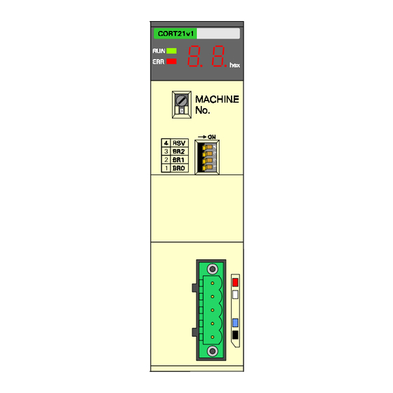
3 Installation This section describes the installation of the C200HW-CORT21-V1 3-1 Physical layout of the Unit............................. 32 3-1-1 LEDs ................................32 3-1-2 7-segment display ............................32 3-1-3 Rotary Switch..............................33 3-1-4 Baud rate switches............................33 3-1-5 BUS Connector............................... 34 3-1-6 Node Address Switches ........................... 35 3-2 Mounting the C200HW-CORT21-V1 ........................ -
Page 49: Physical Layout Of The Unit
DIP switches, and the 5-pin bus connector. The rear view shows the Node Address DIP switches. 3-1-1 LEDs The C200HW-CORT21-V1 has 2 indicator LEDs. These LEDs indicate the status of the Unit in Unit status general. -
Page 50: Rotary Switch
Special I/O Unit connected to the host PLC. If the same Machine number is used for the C200HW-CORT21-V1 and another Special I/O Unit, an "I/O Unit Over" error will occur in the PLC and it will not be possible to start up the network communication. -
Page 51: Bus Connector
Physical layout of the Unit Baud rate (kbit/s) 1000 Note The C200HW-CORT21-V1 allows configuration of any arbitrary baud rate supported by CAN via the Unit settings (DM settings). Refer to appendix D for the definition of these Unit settings. 3-1-5 BUS Connector The CAN bus connector is a 5-pin male open style connector. -
Page 52: Mounting The C200Hw-Cort21-V1
Installation Manual. • The C200HW-CORT21-V1 is a Special I/O Unit. It can be mounted in any slot in the backplane of a CPU Rack or Expansion I/O Rack as long as its Machine number is not the same as the Machine number of another Special I/O Unit within the system. -
Page 53: Setting Up A Network
(CAN_GND, CAN_SHLD, CAN_V+). This type of cable allows a central location of the network power supply and improves protection against electromagnetic disturbances. For industrial CAN applications, OMRON recommends the use of DeviceNet cable, e.g. OMRON DCA1-5C10. -
Page 54: Network Configuration
The last sub-section shows how the configuration can be stored to / restored from the non-volatile memory in the Unit. Enable CANopen Note that the CANopen communication of C200HW-CORT21-V1 must first be enabled (IR n.00) before the Unit can be configured. Start_Remote_Node After completing the desired configuration, the communication does not start until the NMT master gives the command ‘Start_Remote_Node’... - Page 55 0 = PDO valid 1 = PDO not valid Note: C200HW-CORT21-V1 supports only 11-bit identifiers, and no Remote Transmission Requests (RTR). Therefore all its valid PDOs have COB-ID's with the structure 40000xxxh. For PDO linking, only the identifier (xxx) is relevant.
- Page 56 Section 3-3 Setting up a network The configuration is built during the Pre-Operational state. For each data link, the COB-ID of a transmit PDO must be configured to the same value as the COB-ID of receive PDO. Note that the terms ‘transmit’ and ‘receive’ are from the node point of view.
- Page 57 RPDO is transferred to the mapped application objects. Refer to section 1-3-1-1 for general information about the transmission modes. In C200HW-CORT21-V1, asynchronous transmission is triggered by a change in data content. • For TPDOs, a change in the value of an application object results in the transmission of the TPDO(s) to which it is mapped.
-
Page 58: Pdo Mapping Parameters
This configuration procedure is normally taken care of by the configuration tool. Refer to the EDS file of the C200HW-CORT21-V1 to see the default values for the mapping parameters. 3-3-2-3 Heartbeat Time The structure of the Consumer Heartbeat Time is different from the Producer Heartbeat Time. -
Page 59: Guard Time / Life Time Factor
0 means that the Heartbeat monitoring for the indicated Node ID is disabled. Heartbeat error If the C200HW-CORT21-V1 does not receive the Heartbeat within the Heartbeat Time, the Unit indicates this error by IR n+3.11 and on the 7- segment display. It is up to the user to take any further action. When the Unit starts receiving heartbeats again, the error indication will disappear. -
Page 60: Sync Producer / Consumer
COB-ID SYNC message The COB-ID SYNC message is a 32-bit variable. The upper 21 bits in the variable should be set to 0 in C200HW-CORT21-V1 (these are only relevant for SYNC producers and devices with 29-bit identifiers). The lower 11-bits specify the communication identifier of the SYNC Object. -
Page 61: Synchronous Window Length
The configurator can always access the device through these identifiers. The C200HW-CORT21-V1 only supports the mandatory server SDO. This entry is used to configure the Unit. The variables on sub-index 01h and 02h are both 32-bit variables. The upper 21 bits are used to indicate whether the SDO is invalid and whether a 29-bits identifier is used. -
Page 62: Storing / Restoring Of Parameters
Section 3-3 Setting up a network 3-3-2-9 Storing / Restoring of Parameters The C200HW-CORT21-V1 allows storage of parameters of the Communi- Storing Parameters cation Profile Area and of the Manufacturer Specific Profile Area in non- volatile memory. Appendix B lists the stored parameters. - Page 63 Section 3-3 Setting up a network Restoring Parameters The restoring of parameter values to the default values, as defined in the communication and manufacturer specific profile specification, is done via a SDO access to the object at index 1011h. The following figure shows the structure of this object.
-
Page 64: Plc Interface
4 PLC interface This section describes the interface with the user via the PLC system. This includes Unit settings to configure the Unit plus the control and status areas. 4-1 Input and Output Data............................48 4-2 I/O Data mapping..............................49 4-2-1 Application Objects ............................ -
Page 65: Input And Output Data
Section 4-1 Input and Output Data Input and Output Data The C200HW-CORT21-V1 forms a link between two bus systems: the host Link between 2 buses PLC's I/O bus on one side, and the CANopen network on the other. The Unit... -
Page 66: I/O Data Mapping
HR00 2104h HR99 The core of the C200HW-CORT21-V1 is the object dictionary. The Input and Output Application Objects are part of this object dictionary. Every PLC I/O refresh, the input data is transferred via the I/O bus on the PLC backplane to the corresponding Input Application Objects. -
Page 67: Application Objects
Profile. It uses the Manufacturer Specific Profile Area (see section 1-2-2-1). The following figure shows the structure of the Manufacturer Specific Profile Area of the C200HW-CORT21-V1. The input application objects are located at indices 2000h ~ 2004h and the output application objects at indices 2100h ~ 2104h. - Page 68 Section 4-2 I/O Data mapping Index Sub-index Object Default value 2100h Default_Output_Bytes 2100h Number of entries 2100h 8_bit_output1 2100h 8_bit_output2 2100h 8_bit_output3 2100h 8_bit_output4 2101h 8-bit output network variables 2101h Number of entries 2101h 8_bit_output1 2101h 8_bit_output100 2102h 16-bit output network variables 2102h Number of entries 2102h...
-
Page 69: Mapping Of The Application Objects Onto Pdos
Section 4-2 I/O Data mapping The C200HW-CORT21-V1 supports 4 different data types for input and output data: 8-bit data objects 16-bit data objects 32-bit data objects 64-bit data objects The Default_Input_Bytes and Default_Output_Bytes are the application objects that are by default mapped to the four transmit and receive PDOs of the predefined connection set (see also section 1-3-5). -
Page 70: Mapping Of The Application Objects Onto Plc Memory Locations
The application objects at index 2000h and 2100h (Default_Input_Bytes, Default mapping Default_Output_Bytes) are mapped to the status and control area of the C200HW-CORT21-V1 (see section 4-3). Their data content is transferred between the PLC and the Unit in each I/O refresh. Additional mapping If additional objects are required, the Unit settings of the C200HW-CORT21- V1 need to be configured. - Page 71 Number of 8-bit output objects (valid if DM m = 0001) 0000 ~ 0100 0 ~ 100 8-bit objects to be transferred from m+10 C200HW-CORT21-V1 to PLC * other Setting error * Start address range of 16-bit output area m+11...
- Page 72 Section 4-2 I/O Data mapping The setting error(s) is indicated in IR n+3 and IR n+4 (see section 4-3-2) and the ERR LED will be blinking. Only the control and status area is transferred, so no transfer of additional I/O data and also no CANopen communication. If the specified number of objects would make the area exceed the boundary of the PLC's DM, LR, IR or HR area, it is classified as a setting error and the error handling will be the same as in *...
-
Page 73: Mapping Example
C200HW-CORT21-V1 and 5 other CANopen nodes. The machine number of the C200HW-CORT21-V1 is set to 0. There are in total 7 logical connections to the C200HW-CORT21-V1. From the C200HW-CORT21-V1 point of view, connections 1 to 4 are transmit PDOs and connections 5 to 7 are receive PDOs. -
Page 74: Canopen Configuration
Note that the COB-IDs of the other nodes' PDOs (nodes 3 ~ 7) should be set to the same value as the COB-ID of C200HW-CORT21-V1 for the respective connection. So every connection has one unique COB-ID and this must be set on the receiving node as well as on the transmitting node. -
Page 75: Plc Configuration
20030120h 4-2-4-2 PLC configuration By default, the C200HW-CORT21-V1 only transfers the four input and output bytes mapped to the PDOs of the predefined connection set via the control and status area. This is not enough for the network configuration of this example. - Page 76 Note that the data to / from node 3 is transferred via the Default_Input_Bytes (index 2000h) and Default_Output_Bytes (index 2100h) which have a fixed allocation to the control and status area of the C200HW-CORT21-V1. The following table list the DM settings that have to be made to transfer the additional data objects.
-
Page 77: Control And Status Area
IR n+7. The following table gives an overview of the meaning of these words. IR word Meaning Data Direction Control word PLC ! C200HW-CORT21-V1 Input word 1 Input word 2 Status word 1 Status word 2 C200HW-CORT21-V1 ! PLC... -
Page 78: Control Words
0: CANopen communication is disabled. The CANopen data exchange between PLC and CAN-bus is stopped. On a falling edge, the C200HW-CORT21-V1 will first send out an emergency telegram before disabling the communication. The status bits IR n+3.01 and IR n+3.00 will become 0 and the 7-segment display will indicate FFh. - Page 79 1: CANopen communication is enabled. When this bit is first set after power-on or reset of the Unit, the C200HW-CORT21-V1 will send out a standardised boot- up message. After this, the Unit enters Pre-Operational state. After a 1 ! 0 transition was made to disable the CANopen...
-
Page 80: Status Words
Section 4-3 Control and Status area transmit PDOs of the predefined connection set. 4-3-2 Status words The five status words of the C200HW-CORT21-V1 are shown below. 15 14 13 12 11 10 9 IR n+3 CANopen state New User defined CAN message(s) received... - Page 81 Section 4-3 Control and Status area 15 14 13 12 11 10 9 IR n+5 Emergency trigger Error count 15 14 13 12 11 10 9 IR n+6 Application Object 2100h, 01h Application Object 2100h, 02h 15 14 13 12 11 10 9 IR n+7 Application Object 2100h, 03h Application Object 2100h, 04h...
- Page 82 PLC memory. IR n+3.04 Reset node This bit is set for one PLC scan when the C200HW-CORT21-V1 has received the NMT command ‘Reset_Node’. This command will reset all application objects to zero and set the objects of the communication profile area to the power-on values.
- Page 83 This error is also indicated on the 7-segment display (see section 6-5). IR n+3.10 Bus Off If the C200HW-CORT21-V1 detects an abnormal rate of errors on the bus, the Unit will go 'Bus Off'. This means that all CAN(open) communication is stopped. The Unit will attempt to go online again after toggling IR n.03 ‘Start Bus Off recovery’.
- Page 84 ! on, contact your OMRON representative. IR n+3.15 New error(s) in error log The C200HW-CORT21-V1 has an error log for errors which have occurred in IOWR / IORD message communication. If new errors have occurred since the last access to the error log, IR n+3.15 is set.
- Page 85 Section 4-3 Control and Status area...
-
Page 86: Message Communication, Iowr / Iord
5 Message communication, IOWR / IORD This section describes the message communication. The PLC program instructions IOWR and IORD are used to transfer the messages to and from the Unit. 5-1 Message communication............................70 5-2 IOWR / IORD................................ 70 5-3 Error log................................. 72 5-4 Reading the error log ............................. -
Page 87: Message Communication
Functions 2 and 3 can be used to read and modify the object dictionary of the Unit. In order to provide additional flexibility for advanced users, the Unit can be used to transmit and receive user-defined CAN messages. This allows interfacing the C200HW-CORT21-V1 with devices that operate according to vendor- application-specific CAN-based... - Page 88 First destination word value: The start address of the PLC data area to where the message from the Unit is to be transferred. The following table lists the control codes and message lengths for the C200HW-CORT21-V1. Function Control Message Length code...
-
Page 89: Error Log
Section 5-3 Error log Error log The C200HW-CORT21-V1 records the 25 most recent errors that have Log size occurred in the IOWR / IORD message communication. The most recent error will always be put at the first position in the list, shifting previous error down. - Page 90 Section 5-3 Error log Error code Description Applicable to 0410 Object entry does not exist Writing to the local object dictionary 0411 Sub-index does not exist Writing to the local object dictionary 0412 Object entry is read-only Writing to the local object dictionary 0413 Specified data...
-
Page 91: Reading The Error Log
Section 5-4 Reading the error log Reading the error log Control code #0000 The error log can be read with the IORD instruction. The following figure shows the IORD message structure. IORD message structure word n Number of new error codes range: 0000 ~ 9999 since the last access to the log [BCD]... -
Page 92: Writing To The Local Object Dictionary
Section 5-5 Writing to the local object dictionary Writing to the local object dictionary Control code #0001 The following figure shows the IOWR message structure. word n Index object entry [hex] range: 0000h ~ FFFFh IOWR message structure word n+1 Sub-Index object entry [hex] range: 0000h ~ 00FFh word n+2... - Page 93 Section 5-5 Writing to the local object dictionary Example To modify the COB-ID of a PDO: 11.01 IOWR(-) Change_COBID #0002 Control code = #0002 DM400 Source of message #1002 Mach.No.1, message length 2 words IORD (-) #0002 Control code = #0002 Mach.No.1, message length 3 words #1003 DM402...
-
Page 94: Reading From The Local Object Dictionary
Section 5-6 Reading from the local object dictionary Reading from the local object dictionary Control code #0002 Reading from the local object dictionary requires a combination of the IOWR and IORD instructions. The IOWR instruction indicates to the Unit which object entry to read. - Page 95 Section 5-6 Reading from the local object dictionary Example The following example shows how the COB-ID of RPDO1 (object index 1400h, sub-index 1) is read. In this example, the Mach.No. is set to ‘1’. PLC memory address Contents Meaning DM0200 1400 Index of object to be read DM0201...
-
Page 96: Transmitting A User Defined Can Message
If no other node is connected to the network, or if the CAN interface of the Unit is in error, the C200HW-CORT21-V1 will not be able to transmit the message. After a time-out of 50 ms, the error code 0431 is added to the error Transmission time-out log. -
Page 97: Receiving A User Defined Can Message
Receiving a user defined CAN message Control code #0004 The C200HW-CORT21-V1 can receive arbitrary CAN messages with a combination of the IOWR instruction and the I/O refresh. If it is not required that the CANopen protocol is active at the same time, IR n.00 can be set to ‘0’. - Page 98 = 010B, word n+1 = 0114, word n+2 = 0001 Note The C200HW-CORT21-V1 ignores bits 11 to 15 of word n ~ word n+2 of the IOWR message structure. Also, the Unit does not check the validity of word n ~ word n+2 e.g.
- Page 99 Section 5-8 Receiving a user defined CAN message Message buffer The received message(s) are first stored in a buffer in the Unit. Up to 15 messages can be stored. The last received message is always stored at the top of the buffer and if there are already 15 messages stored, the oldest message is shifted out of the buffer.
- Page 100 • the scan time of the PLC is (fixed to) 8 ms. The C200HW-CORT21-V1 should be programmed to only receive the 32-bit counter value and the 8-bit input value. The Unit should ignore the clock messages, which would overflow the buffer (40 messages per PLC scan).
- Page 101 Section 5-8 Receiving a user defined CAN message PLC memory address Contents Meaning DM0607 0280 Message with ID = 0280 DM0608 0004 Length = 4 bytes DM0609 1003 Data = 000F1003h DM0610 000F DM0611 0000 Ignore DM0612 0000 DM0613 0282 Message with ID = 0282 DM0614 0001...
-
Page 102: Error Handling And Status
6 Error Handling and Status This section gives an overview of the implemented error handling and status indication mechanisms. 6-1 Introduction................................86 6-2 Emergency message............................... 87 6-3 Error Register, Predefined Error Field ........................90 6-4 Fatal PLC error handling ............................91 6-5 LEDs, 7-Segment Display ............................. -
Page 103: Introduction
Section 6-1 Introduction Introduction The C200HW-CORT21-V1 uses several error detection and error handling mechanisms. Error checking CAN CANopen is based on the serial bus protocol of CAN (see section 1-2-1). The data link layer of the CAN protocol combines 5 error detection mechanisms (CRC check, frame check, Ack check, bit check, bit stuffing check). -
Page 104: Emergency Message
Section 6-2 Emergency message Emergency message A general description of the emergency message can be found in section 1-3-3-3. The figure below shows the meaning of each byte in the emergency message. Byte 0 Byte 1 Byte 2 Byte 3 Byte 4 Byte 5 Byte 6... - Page 105 PDO length error Comm Err.00 Receive queue overflow This bit is set when the C200HW-CORT21-V1 is not able to process all the incoming messages that it was configured to receive. This bit is turned off as soon as the receive queue did not overflow for at least 100 ms.
- Page 106 Emergency message Comm Err.04 PDO length error If the C200HW-CORT21-V1 receives a PDO with fewer data bytes than configured, the Unit sends out an emergency message with this bit set. This bit is negated as soon as a PDO is received with the correct number of data bytes or more.
-
Page 107: Error Register, Predefined Error Field
Fatal PLC error Non-volatile memory error Error Register, Predefined Error Field The C200HW-CORT21-V1 has two object entries in the object dictionary that indicate the actual and previous errors since the last time the Unit was reset. Error Register – Object entry 1001h The error register is a simple 8-bit variable that stores the actual errors. -
Page 108: Fatal Plc Error Handling
The error history can be cleared by writing ‘0’ to sub-index 00h. Fatal PLC error handling The C200HW-CORT21-V1 informs the CANopen network when a fatal PLC error has occurred. A fatal PLC error stops the execution of the ladder program and resets the complete IR area. -
Page 109: Leds, 7-Segment Display
Section 6-5 LEDs, 7-Segment Display LEDs, 7-Segment Display The Unit has two LEDs and two 7-segment displays to visualise its status. The layout is shown in the picture below. The two LEDs (RUN, ERR) indicate the status of the Unit in general. LEDs Colour State... -
Page 110: Flow Diagrams
Flow diagrams The next two pages show basic flow diagrams of the C200HW-CORT21-V1. These flow diagrams give a better understanding of the different states and state transitions, and they show the relationship of the different status and error handling mechanisms. - Page 111 Section 6-6 Flow diagrams Power-on or Reset Start RUN LED = Blinking ERR LED = OFF Initialise hardware 7-Segment display = OFF and software IR n+3 = 0000 0000 0000 0000 No CAN(open) communication RUN LED = OFF ERR LED = ON 7-Segment display = OFF...
- Page 112 Section 6-6 Flow diagrams I/O Refresh Start Data PLC --> Unit (Input Application Objects) RPDO transmission type Data Unit --> PLC RPDO data asynchronous or synchronous (Output received from CAN and configured SYNC object Application bus? received? Objects) Control words --> Unit (IR n ~ IR n+2) Status words -->...
- Page 113 Section 6-6 Flow diagrams...
-
Page 114: Troubleshooting And Maintenance
7 Troubleshooting and Maintenance This section describes the troubleshooting procedures and maintenance operations needed to keep the CANopen network operating properly. 7-1 Error Indicators ..............................98 7-2 Troubleshooting ..............................98 7-3 Maintenance................................. 104 7-3-1 Cleaning ............................... 104 7-3-2 Inspection ..............................104 7-3-3 Replacement of Units............................ -
Page 115: Error Indicators
• I/O data communication problems • Message communication problems General Note: when replacing the C200HW-CORT21-V1, make sure that any CANopen configuration data that was stored in the Unit's non-volatile memory is written to the new Unit before putting the system in operation. - Page 116 The PLC’s power is off. Turn the PLC’s power supply on. Blinking. The Unit is defective. Replace the C200HW-CORT21-V1. The RUN LED is The same Unit number has been set on Make sure that the same Unit number is not Blinking.
- Page 117 Section 7-2 Troubleshooting Configuration problems (continued) Description Possible cause Possible remedy Not able to store / Incorrect signature. To store parameters, the signature ‘save’ has restore parameters. to be written to sub-index 01h of index 1010h. To restore parameters, the signature ‘load’ has to be written to sub-index 01h of index 1011h.
- Page 118 Machine Numbers. The Unit is defective. Replace the C200HW-CORT21-V1. Data in the mapped Data that is mapped in the IR- or LR area is If the Host PLC was not switched to / from...
- Page 119 (EQ-flag is not set). indicated by an IOWR. The Unit is defective. Replace the C200HW-CORT21-V1. Not able to access The object entry does not exist or has the Read the error log to find the cause.
- Page 120 Configure all the units on the network to the the other node on the network. same baud rate. Not all user defined The C200HW-CORT21-V1 can buffer up to 15 Reduce the data production rate of the CAN messages are messages between PLC I/O refreshes. If the transmitting node.
-
Page 121: Maintenance
Section 7-3 Maintenance Maintenance This section describes the routine cleaning and inspection recommended as regular maintenance. 7-3-1 Cleaning Clean the CANopen Slave Units regularly as described below in order to keep it in optimal operating condition. • Wipe the Unit with a dry, soft cloth for regular cleaning. •... -
Page 122: Replacement Of Units
Note Do not plug or unplug the C200HW-CORT21-V1 on the PLC backplane while the PLC is powered. Doing so may result in damage to the Unit and/or the... - Page 123 Section 7-3 Maintenance...
-
Page 124: Appendix Aeds-File C200Hw-Cort21-V1
Appendix A EDS-file C200HW-CORT21-V1 [FileInfo] [Comments] DefaultValue=0x00000083 CreatedBy=OMRON Europe B.V. - ADDC Lines=8 PDOMapping=0 FA Communications Group Line1=EDS file for C200HW-CORT21-V1 ModifiedBy=OMRON Europe B.V. - ADDC Line2= [OptionalObjects] FA Communications Group Line3=Default four 8-bit TX/RX objects SupportedObjects=30 Description=EDS file for C200HW-... - Page 125 [1008] DataType=0x0005 ParameterName=Standard Error Field ParameterName=Manufacturer Device AccessType=ro Name ObjectType=0x7 DefaultValue=1 ObjectType=0x7 DataType=0x0007 PDOMapping=0 DataType=0x0009 AccessType=ro AccessType=const DefaultValue=0 [1010sub1] DefaultValue=C200HW-CORT21-V1 PDOMapping=0 ParameterName=Save all Parameters PDOMapping=0 ObjectType=0x7 [1003sub4] DataType=0x0007 [1009] ParameterName=Standard Error Field AccessType=rw ParameterName=Manufacturer Hardware ObjectType=0x7 PDOMapping=0 Version DataType=0x0007 ObjectType=0x7...
- Page 126 [1016] AccessType=ro DefaultValue=$NODEID+0x40000300 ParameterName=Consumer Heartbeat DefaultValue=$NODEID+0x580 PDOMapping=0 Time PDOMapping=0 LowLimit=0x40000001 ObjectType=0x8 HighLimit=0xC00007FF SubNumber=2 [1400] ParameterName=RPDO #0 [1401sub2] [1016sub0] Communication ParameterName=Transmission Type Parameter ParameterName=Number of Entries ObjectType=0x7 ObjectType=0x9 ObjectType=0x7 DataType=0x0005 SubNumber=3 DataType=0x0005 AccessType=rw AccessType=ro DefaultValue=0xFE [1400sub0] DefaultValue=1 PDOMapping=0 ParameterName=Number of Entries PDOMapping=0 LowLimit=0x00 ObjectType=0x7...
- Page 127 ObjectType=0x7 DataType=0x0005 AccessType=rw DataType=0x0005 AccessType=rw DefaultValue=0x21000408 AccessType=ro DefaultValue=1 PDOMapping=0 DefaultValue=2 PDOMapping=0 PDOMapping=0 LowLimit=0 [1800] HighLimit=8 ParameterName=TPDO #0 Communication [1403sub1] Parameter ParameterName=COB-ID [1601sub1] ObjectType=0x9 ObjectType=0x7 ParameterName=Mapping Entry #1 SubNumber=3 DataType=0x0007 ObjectType=0x7 AccessType=rw DataType=0x0007 [1800sub0] DefaultValue=$NODEID+0x40000500 AccessType=rw ParameterName=Number of Entries PDOMapping=0 DefaultValue=0x21000208 ObjectType=0x7 LowLimit=0x40000001 PDOMapping=0...
- Page 128 DefaultValue=$NODEID+0x40000280 ObjectType=0x7 DataType=0x0005 PDOMapping=0 DataType=0x0005 AccessType=rw LowLimit=0x40000001 AccessType=ro DefaultValue=1 HighLimit=0xC00007FF DefaultValue=2 PDOMapping=0 PDOMapping=0 LowLimit=0 [1801sub2] HighLimit=8 ParameterName=Transmission Type [1803sub1] ObjectType=0x7 ParameterName=COB-ID [1a01sub1] DataType=0x0005 ObjectType=0x7 ParameterName=Mapping Entry #1 AccessType=rw DataType=0x0007 ObjectType=0x7 DefaultValue=0xFE AccessType=rw DataType=0x0007 PDOMapping=0 DefaultValue=$NODEID+0x40000480 AccessType=rw LowLimit=0x00 PDOMapping=0 DefaultValue=0x20000208 HighLimit=0xFE LowLimit=0x40000001 PDOMapping=0 HighLimit=0xC00007FF...
- Page 129 AccessType=rw [2100sub0] Dir4=ro DefaultValue=0x20000408 ParameterName=Number of elements Range4=0x2004-0x2004 PDOMapping=0 ObjectType=0x7 PPOffset4=0 DataType=0x0005 MaxCnt4=25 [ManufacturerObjects] AccessType=ro Type5=0x0005 SupportedObjects=2 DefaultValue=4 Dir5=rww 1=0x2000 PDOMapping=0 Range5=0x2101-0x2101 2=0x2100 PPOffset5=0 [2100sub1] MaxCnt5=100 [2000] ParameterName=Default_Output_Byte1 Type6=0x0006 ParameterName=Default_Input_Bytes ObjectType=0x7 Dir6=rww ObjectType=0x8 DataType=0x0005 Range6=0x2102-0x2102 SubNumber=5 AccessType=rww PPOffset6=0 DefaultValue=0x00 MaxCnt6=100 [2000sub0] PDOMapping=1 Type7=0x0007...
-
Page 130: Appendix B Stored Parameters
Appendix B Stored Parameters Default Value According Index Sub index Name Profile 1005h COB-ID SYNC Message 0000 0080h 1016h Consumer Heartbeat Time 0000 0000h 1017h Producer Heartbeat Time 0000h COB-ID RPDO1 0000 0200h + Node ID 1400h Transmission Type RPDO1 COB-ID RPDO2 0000 0300h + Node ID 1401h... - Page 131 Default Value According Index Sub index Name Profile mapped object TPDO1 2000 0108h 1A00h 2 ~ 8 mapped object TPDO1 0000 0000h mapped object TPDO2 2000 0208h 1A01h 2 ~ 8 mapped object TPDO2 0000 0000h mapped object TPDO3 2000 0308h 1A02h 2 ~ 8 mapped object TPDO3...
-
Page 132: Appendix Ccs1 Plc Series Compatibility
Appendix C CS1 PLC series compatibility The C200HW-CORT21-V1 can also be installed in OMRON CS1 PLC systems, which provide a C200H- compatible I/O bus. However, the internal memory organisation in the CS1 PLC differs from that of the C200H series. The following table shows the relation between the C200H-series memory addresses used throughout this manual, and the corresponding addresses in the CS1 PLC series. -
Page 134: Appendix D Baud Rate Configuration Via Unit Settings
Appendix D Baud rate configuration via Unit settings The standard CANopen baud rates are selectable via the DIP-switches at the front of the Unit (see section 3-1-4). However, if a different baud rate is required, it is possible to configure this via the Unit settings. The Unit settings only overrule the DIP-switch settings when all the configured values are within the specified ranges. -
Page 136: Index
Index (continued) Address, Bus............35 EQ Flag ..............71 Address, PLC Memory........53, 63 ERR LED ..........55, 66, 92 Application Objects .... 5, 23, 39, 49-55, 62, 67 Error, Communication ......66, 72, 87-88 Asynchronous PDO......8, 23, 28, 40, 48 Error, Device ..........87-89 Error, Fatal PLC .........61, 67, 89, 91 Error Code............ - Page 137 Index (continued) Installation ............31 Parameters, Store/Restore....45, 46, 75, 113 EMC ............... xiv Grounding ............xiii Cyclic/Acyclic.........8, 23, 40 Humidity, Temperature ........xii Granularity...........9, 41 Safety ............xii, xiii Linking ..........16, 23, 38 IORD/IOWR Instructions ........22, 70 Mapping........9, 17, 23, 41, 52 ISO 11898 ..........3, 22, 36 Receive/Transmit ........8, 23, 40 Transmission types .........40...
- Page 138 Index Termination ............36 Time Stamp Object ........12, 17 TPDO ............8, 23, 40 Troubleshooting ...........97 Unit Settings..........22, 53-59 User-defined CAN, Receive....29, 65, 70, 80 User-defined CAN, Transmit......70, 79 Variables, Attributes ..........38 Window Length .........8, 11, 44 7-Segment Display..........92...
-
Page 140: Revision History
Revision History A manual revision code appears as a suffix to the catalog number on the front cover of the manual. Cat. No. W904-E2-2 Revision code The following table outlines the changes made to the manual during each revision. Page numbers refer to the previous version. - Page 142 Regional Headquarters OMRON EUROPE B.V. Wegalaan 67-69, NL-2132 JD Hoofddorp The Netherlands Tel: +31 (0)23 5681-300 Fax: +31 (0)23 5681-388...
- Page 143 OMRON Authorized Distributor: Cat. No. W904-E2-2 Note: Specifications subject to change without notice. Printed in the Netherlands...
- Page 144 Below is a list of articles with direct links to our shop Electric Automation Network where you can see: • Quote per purchase volume in real time. • Online documentation and datasheets of all products. • Estimated delivery time enquiry in real time. •...
Need help?
Do you have a question about the C200HW-CORT21-V1 and is the answer not in the manual?
Questions and answers