
Related Manuals for Omron GRT1-PNT - DATASHEET 2


Summary of Contents for Omron GRT1-PNT - DATASHEET 2
- Page 1 Cat. No. W13E-EN-01 SmartSlice GRT1-Series GRT1-PNT PROFINET IO Communication Unit OPERATION MANUAL...
- Page 3 OMRON product references All OMRON products are capitalized in this manual. The first letter of the word Unit is also capitalized when it refers to an OMRON product, regardless of whether it appears in the proper name of the product.
-
Page 5: Table Of Contents
2-5 Setting up the PROFINET IO network....................32 2-6 Installation of Configuration Software..................... 38 SECTION 3 Set-up and operation 3-1 Device name setting and I/O allocation ....................42 3-2 Unit functions............................46 3-3 GRT1-END-M Unit functions ........................52 3-4 Set-up the GRT1-PNT Configuration ..................... 54 3-5 Monitoring the GRT1-PNT........................ - Page 6 PROFINET IO alarm messages B-1 Introduction ............................91 B-2 Alarm messages ............................ 92 Appendix C Explicit messages C-1 Basic format of explicit messages......................93 C-2 Explicit messages common to all IO devices..................95 C-3 Example of using explicit messages ...................... 96...
-
Page 7: Precautions
This chapter provides general precautions for using the GRT1-series modules, Programmable Controllers and related devices. The information contained in this section is important for the safe and reliable operation of the GRT1- PNT PROFINET IO Communication Unit. You must read this section and understand the information contained before attempting to set up or operate a GRT1-PNT PROFINET IO Communication Unit and related systems. -
Page 8: Intended Audience
WARNING It is extremely important that the Unit is used for the specified purpose and under the specified conditions, especially in applications that can directly or indirectly affect human life. You must consult with your OMRON representative before using the Unit in a system in the above mentioned applications. -
Page 9: Operating Environment Precautions
PROGRAM mode). Confirm safety thoroughly in advance before changing the status of any part of memory allocated to Output Units, Special I/O Units, or CPU Bus Units. Any changes to the data allocated to any Unit may result in unexpected operation of the loads connected to the Unit. -
Page 10: Application Precautions
Install double safety mechanisms to ensure safety against incorrect signals that may be produced by broken signal lines or momentary power interruptions. • When adding a new device to the network, make sure that the baud rate is the same as other stations. •... -
Page 11: Conformance To Ec Directives
• • Fail-safe measures must be taken by the customer to ensure safety in the event of incorrect, missing, or abnormal signals caused by broken signal lines, momentary power interruptions, or other causes.Not doing so may result in serious accidents. -
Page 12: Conformance To Ec Directives
Conformance to EC Directives... -
Page 13: Features And Specifications
Features and specifications This section provides an introductory overview of the GRT1 series SmartSlice I/O Units and the GRT1-PNT PROFINET IO Communication Unit, its functions and how to set up and configure it for a PROFINET network. SECTION 1 Features and specifications 1-1 Overview of GRT1-series SmartSlice I/O Units .................. -
Page 14: Overview Of Grt1-Series Smartslice I/O Units
Overview of GRT1-series SmartSlice I/O Units The GRT1-Series SmartSlice I/O Units are building-block style I/O Devices, which can be expanded in small I/O increments. This provides the possibility to configure I/O systems which exactly match the various customer applications. SmartSlice I/O Units communicate with the PROFINET IO Controller Unit by remote I/O communication through a PROFINET IO Communication Unit. -
Page 15: Grt1-Pnt Profinet Io Communication Unit
MRP Ring Redundancy To avoid a single network failure causing communication failure within a large part of the network, the units can be set up in a ring topology. MRP Ring Redundancy specified... - Page 16 Note 1 Unlike the standard End Unit, the Memory End Unit will count as one SmartSlice I/O Unit. Up to 63 SmartSlice I/O Units can be connected to one PROFINET IO Com- munication Unit when the GRT1-END-M is used.
- Page 17 GRT1-PNT PROFINET IO Communication Unit Section 1-2 Switch Figure 1.2: A single GRT1-PNT connects to multiple I/O blocks via Turnback units. 1 Remote I/O data is collected from the connected SmartSlice I/O Units and exchanged with the IO Controller Unit 2 Acyclic messages are used to monitor operation and write parameters to the SmartSlice I/O Units.
- Page 18 Unit type SmartSlice GRT1 series Model GRT1-PNT Mounting position DIN Rail mounted + 10 % / − 15 % (20.4 V Power supply 24 V to 26.4 V Current consumption 140 mA (max), 120 mA typical at 24 V Dimensions (WxHxD)
- Page 19 I/O Units Connected directly to the GRT1-PNT or via turnback extension units. Turnback cable Length 1 m, up to 2 cables can be connected. SmartSlice I/O Unit connections Building-block style configuration (Units connect with Turn- back cables) Base block power supply...
- Page 20 GRT1-PNT PROFINET IO Communication Unit Section 1-2 External dimensions 2.85 OMRON GRT1-PNT UNIT PWR I/O PWR REGS BACK UNIT DC24V INPUT 23.1 2.85 13.5 24.8 14.3 27.1 36.7 61.2 69.7 Figure 1.2.3: GRT1-PNT PROFINET IO Communication Unit external dimensions...
-
Page 21: Grt1-End-M Memory End Unit
SmartSlice GRT1 series Model GRT1-END-M Mounting position DIN Rail mounted Current consumption 30 mA (max), 24 mA typical at 24 V Dimensions (WxHxD) 19.5 x 83.5 x 55.7 mm Weight 60 g (typical) −10 °C to +55 °C (no icing or condensation) -
Page 22: Grt1-Pnt Configuration
The drawback of the GSD file is that - unlike the GRT1-PNT DTM - it only provides setting options for configuring the PROFINET IO. The GSD file does not provide the means to access data of the SmartSlice I/O Units directly. - Page 23 Device DTM, an FDT/DTM interface between the FDT Container program and GSD files. Alternatively, this DTM can be used to set up an IO Controller Unit, using the GRT1-PNT GSD file. This Generic IO Device DTM however, does not provide the means to access data of the SmartSlice I/O Units directly.
-
Page 24: Basic Operating Procedure
Basic operating procedure 1-5-1 Overview The following diagram provides an overview of the installation procedures. For experienced installation engineers, this may provide sufficient information. For others, cross-references are made to various sections of this manual where more explicit information is given. - Page 25 PROFINET IO Controller Unit. 4 Turn ON the power to the Unit and the I/O. 5 Turn ON (from OFF to ON) DIP switch 1 on the front of the PROFINET IO Communication Unit. When switch 1 is turned ON, the existing SmartSlice I/O Unit configuration (connection order and I/O size) is registered in the PROFINET IO Communication Unit as a registered table.
- Page 26 Basic operating procedure Section 1-5...
-
Page 27: Installation And Wiring
This section shows the GRT1-series PROFINET IO Communication Unit and identifies its controls and indicators. It contains the procedures for installing and wiring the Communication Unit as well as the GRT1- series SmartSlice I/O Units. It also contains the procedures for setting up the PROFINET IO network. -
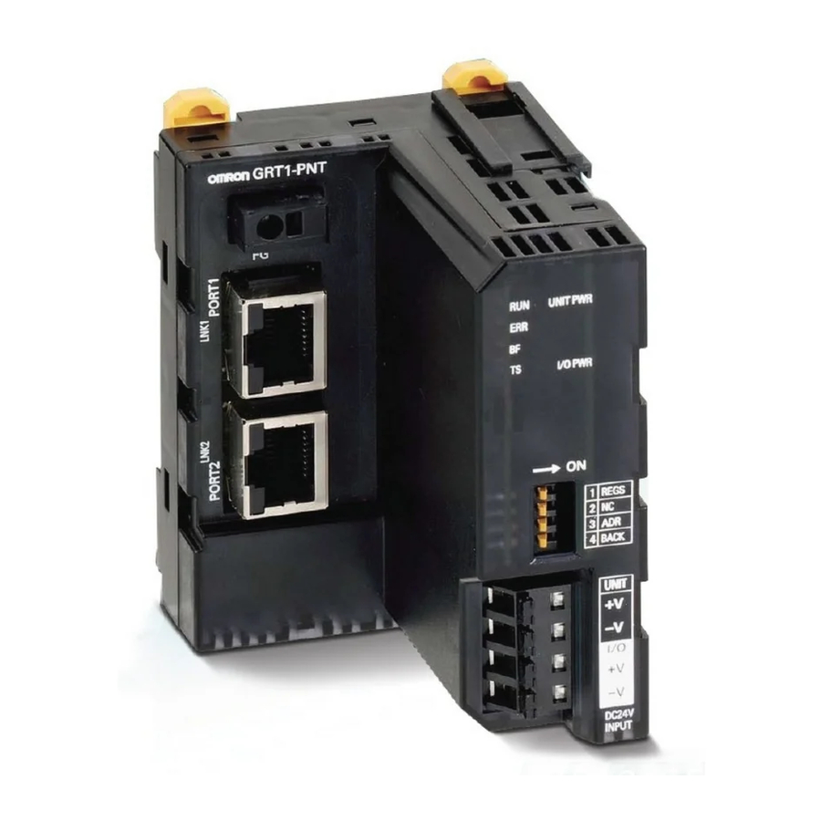
Page 28: Grt1-Pnt Unit Components
Link activity LED indicators (1), the Status LED indicators (3), the Field Ground Terminal (2), the DIP switches (4) and the power supply terminals (5 and 6) on the front side of the PROFINET IO Communication Unit. Each of these components is explained in the following sections. - Page 29 (0.5 to 2.0 mm Pin terminal Strip Length Strip wire between 8 mm and 10 mm of insulation at the ends of the wires Pin Terminal Length (stranded or solid wire) or use pin terminals with a pin (conductor) length of 8 mm to 10 mm.
- Page 30 SmartSlice I/O Unit settings. Fatal communication error occurred. UNIT PWR Green Not lit Power supply to the Unit is not present (All other LED indicators are also OFF). Power supply to the Unit is present. I/O PWR Green Not lit Power supply to the SmartSlice I/O Unit is not present.
- Page 31 BACK Backup Trigger Note It is recommended to use the features that are made available by DIP switches 1, 3 and 4 (as discussed on the next page). DIP Switch 1: REGS If DIP switch 1 is turned from OFF to ON while the Unit’s power is ON, the existing SmartSlice I/O Unit configuration (connection order and I/O size) is registered in the PROFINET IO Communication Unit as a registered table.
- Page 32 Automatic restore function enabled (when pin 1 is ON). DIP Switch 4: BACK When DIP switch 1 is ON (registered table enabled) and DIP switch 4 is turned OFF to ON, the parameter data of all connected SmartSlice I/O Units is backed up in the Communication Unit.
- Page 33 Note System power supply and External I/O power supply are not transferred through the GCN2-100 Turnback cable. The GRT1-TBR Right Turnback Units provide the same set of Power Supply terminals as the PROFINET IO Communication Unit.
-
Page 34: Grt1-End-M Unit Components
GRT1-END-M Unit components Section 2-2 GRT1-END-M Unit components 2-2-1 Overview The illustration below shows the front view of the GRT1-END-M with the TS LED indicator (1). END-M Figure 2.2.1: GRT1-END-M overview 2-2-2 LED Indicators The GRT1-END-M Memory End Unit uses a single LED indicator to indicate status. -
Page 35: Installing The Grt1-Pnt Unit
Provide separate conduits or ducts for the control lines to prevent noise from high-tension lines or power lines. The SmartSlice I/O system is installed and set up as a PROFINET IO Device. A PROFINET IO communication cable connects the PROFINET IO Communication Unit and the IO Controller. - Page 36 To install a PROFINET IO Communication Unit on the DIN Rail, press the Unit onto the DIN Rail from the front. Press the Unit firmly until it clicks, indicating that the Unit’s DIN Rail Mounting Hooks have all locked onto the DIN Rail.
- Page 37 Connect the first SmartSlice I/O Unit to the PROFINET IO Communication Unit by aligning the sides of the Units and sliding in the SmartSlice I/O Unit from the front. Insert the Unit until it clicks, indicating that the Unit has locked onto the DIN Rail.
- Page 38 (for right side of block) (for left side of block) Note The Turnback Units can be used to divide a SmartSlice I/O System into up to three blocks. Connecting an End Unit At the end of the last block, mount a GRT1-END End Unit or a GRT1-END-M Memory End Unit.
- Page 39 Plates on both sides of the System. 1 First hook the bottom of the End Plate on the bottom edge of the DIN Rail. 2 Attach the top of the End Plate, and pull the End Plate down onto the top edge of the DIN Rail.
-
Page 40: Wiring The Grt1-Pnt Unit
Unit power supply to the Left Turnback Unit (GRT1- TBL) of the next expansion block. Note 1 The GRT1-TBL is equipped with separate power supply terminals for the Unit power supply and I/O power supply. When dividing the supply power, always wire (supply) the power from the... - Page 41 SmartSlice I/O Units at the desired point with a GRT1-PD2 I/O Power Supply Unit and provide a separate external I/O power supply. 3 It is also possible to provide a separate external I/O power supply at a Left Turnback Unit (GRT1-TBL). Note 1 The GRT1-TBL is equipped with separate power supply terminals for the Unit power supply and I/O power supply.
- Page 42 The GRT1-TBL Left Turnback Unit and GRT1-PD2 I/O Power Supply Unit have the same screwless clamping power supply terminals as the PROFINET IO Communication Unit. These terminals are wired in the same way as the PROFINET IO Communication Unit’s terminals, by inserting the power supply wires. Removing Wires To remove the wires press the release button above the terminal hole using a slotted precision screwdriver and pull out the wire.
- Page 43 Note The GCN2-100 Turnback Cable does not propagate supply power from one block to the next one. Always wire (supply) the power to the GRT1-TBL Left Turnback Unit from the same power supply that supplies the PROFINET IO Communication Unit.
-
Page 44: Setting Up The Profinet Io Network
PROFINET IO communication. 2-5-1-1 Line A line topology consists of placing multiple IO Devices in series. Many IO Devices, such as the GRT1-PNT Unit, have an ethernet switch integrated in the Unit. This creates an easy way to connect the IO Devices. - Page 45 Setting up the PROFINET IO network Section 2-5 2-5-1-2 Star The star topology is the standard-most topology for Ethernet networks. A central switch will allow communication to all individually attached devices. Switch Benefits: • Flexible adding and removing devices without interrupting the network.
- Page 46 Setting up the PROFINET IO network Section 2-5 2-5-1-3 Tree The tree topology is a hierarchial combination of multiple star topologies interconnected with each other. Switch Switch Benefits: • Shorter data communication at local node. Avoiding excessive traffic through a single switch.
- Page 47 The network requires an MRP manager to facilitate the redundancy. As an MRP client, there are no specific settings required for the GRT1-PNT Unit. Please refer to the manual of the used MRP manager unit for details on how to set up and operate the MRP network.
- Page 48 PROFINET IO Controller redundancy The PROFINET IO Controller redundancy feature ensures seamless change- over of active PLC / IO Controller to the standby PLC / IO Controller in case of malfunction. To support the PROFINET IO Controller redundancy, a redundancy Function Block can be downloaded from the OMRON website.
- Page 49 Tree of the network by drag-dropping from the Device Catalogue. Assign the modules for each individual IO Device. 6 Allocate the modules of the IO Devices to the intended PLC memory areas. 7 Download the configuration to the Unit. 8 Confirm proper operation. Checking the Monitoring GUI of DTM and LED...
-
Page 50: Installation Of Configuration Software
GRT1-PNT. For this purpose OMRON provides the GRT1-PNT DTM via the OMRON web site http://www.omron-industrial.com/ After installation the DTM will run in the FDT Container, allowing the user to set up the I/O configuration and set the parameters of the GRT1-PNT and of the individual SmartSlice I/O Units. - Page 51 It can now be used to setup a PROFINET IO network and configure the Controller Unit. Note In case the required PROFINET IO Controller DTM has not been installed, this needs to be done first to allow the full features of the GRT1-PNT DTM to be used.
- Page 52 SmartSlice I/O Units. The GRT1-PNT DTM does provide this capability. The next section will discuss the features of the GRT1-PNT in detail as well as how to set up, configure and operate the SmartSlice I/O System in a...
-
Page 53: Set-Up And Operation
This section describes the operational aspects of the GRT1-PNT and the SmartSlice I/O System. It first discusses the operational features which can be used, prior to describing how to set up the system and how to operate and monitor it on a PROFINET IO network. -
Page 54: Device Name Setting And I/O Allocation
LEDs for 3 seconds, identifying the Unit on the rack. Note 1 Be sure to have unique Device names for each of the IO Devices in the network. As the name is used as identification, duplicate names will result in communication failure. - Page 55 I/O Units in the SmartSlice I/O system. These unit numbers are assigned automatically at start-up, when the power is turned ON. The numbering starts from #1 and runs from left to right. It is not necessary for the user to set these numbers.
- Page 56 5 Word-sized SmartSlice I/O Units, e.g. GRT1-AD2, GRT1-DA2V are mapped to one or more words, from the low to the high word address. 6 Total size of mapped I/O data can be 64 words output and 64 words input. I/O Allocation Example...
- Page 57 Amount of I/O data being used + 1 word Unit status flags Communication Unit’s These flags can be used to monitor the status of the connection between the Status Flags GRT1-PNT and the SmartSlice I/O Units as well as the status of the SmartSlice I/O Units themselves.
-
Page 58: Unit Functions
Communication Unit while the SmartSlice I/O Units’ power supply is ON. The registered table is enabled if DIP switch 1 is ON when the power is turned ON. If DIP switch 1 is OFF when the power is turned ON, the registered table is disabled and the Communication Unit will automatically detect the actual I/O configuration and start communication. - Page 59 Note The configuration information records the order that the SmartSlice I/O Units are con- nected and the I/O size (input or output, number of bits) of each SmartSlice I/O Unit. The I/O Unit model numbers are not recorded. Comparison with the...
- Page 60 1,2,3... 1 Verify that the power is ON, DIP switch 1 (REGS) is ON, and all of the SmartSlice I/O Units are participating in I/O communication. 2 Turn DIP switch 4 (BACK) ON, then OFF, and then ON again within 3 seconds to start the back up.
- Page 61 The data will not be restored properly if the power is turned OFF. 2 When a SmartSlice I/O Unit has been replaced with the power ON and the new I/O Unit joins I/O communication, the new Unit will be compared to the previous one and the parameter data restore operation will start automatically.
- Page 62 4 Only replace one I/O Unit at a time. 5 Always replace the I/O Unit with the same model of I/O Unit. If a Unit is replaced with a different model, there may be unexpected outputs and the restore operation may not be completed properly.
- Page 63 3 In CX-ConfiguratorFDT right-click on the icon of the GRT1-PNT, and select Diagnosis. 4 Select the I/O Unit Error History tab in the Diagnosis Window. The communication error history for the most recent errors that occurred will be displayed, as shown in the following image. To display the most recent error history, click the Update button.
-
Page 64: Grt1-End-M Unit Functions
Name of the IO Device, which is used for the identification within the PROFINET network. When configuring the PROFINET network, any Device Name written by the Scan Tool of the IO Controller DTM to the IO Device will be written immediately into the END-M Unit. - Page 65 SmartSlice I/O Unit’s Alarm Status Area provides notification of serious errors detected in the Unit. When any of these flags goes ON, bit 3 of the Communications Unit’s Status Flags is turned ON and that information is transmitted to the Controller Unit.
-
Page 66: Set-Up The Grt1-Pnt Configuration
SmartSlice I/O Unit A direct ethernet connection of the Personal Computer to the PROFINET IO network can also be used to connect to the PLC CPU through the IO Controller. It can be used to configure and monitor the PLC and the PROFINET IO Controller. - Page 67 Comment The comment field contains comments or descriptions of the station. Name of Station This field contains the name of the station, by which it is known to the IO Controller. IP settings This sections contains the IP address, network mask and gateway address.
- Page 68 SmartSlice I/O Unit Note 1 Not shown in the list is the first input word, containing the GRT1-PNT Unit status word (refer to section 3-1-4 SmartSlice I/O allocation to the GRT1-PNT unit for an explanation on this word). The GRT1-PNT DTM automatically inserts the status word in the I/O Configuration.
- Page 69 Note 1 In order to download/upload settings for individual SmartSlice I/O Units, the DTM has to be on-line with the physical GRT1-PNT Unit, i.e. it has to be able to establish a connection with the device. 2 In the case of the GRT1-AD2 some parameter settings will affect the I/O Configura- tion, i.e.
- Page 70 Pressing the Compare button will initiate a comparison between the I/O Configuration and parameters of all SmartSlice I/O Units and the data stored within the DTM. In case a mismatch is found, a warning screen will pop up to notify the user.
- Page 71 5 If applicable, repeat the previous steps to add another module. Observe the following. • The 2- and 4-point Digital Units occupy 2 or 4 bits of I/O data. Adjacent digital Input Units or Output Units must be assembled in to 1 word. •...
- Page 72 Generic Device IO DTM is shown in the window below. The window above shows the SmartSlice I/O Input data, mapped onto CIO 3300 to 3304. The first row indicates the COM Status word, the other rows indicate the GRT1-ID Units.
- Page 73 Set-up the GRT1-PNT Configuration Section 3-4 For information on how to map the I/O data on to the PLC memory, refer to the PROFINET IO Controller Unit Operation Manual (W12E).
-
Page 74: Monitoring The Grt1-Pnt
PROFINET IO Data with the PROFINET IO Controller. These flags can be used to monitor the status of the connection between the GRT1-PNT and the SmartSlice I/O Units as well as the status of the SmartSlice I/O Units themselves. - Page 75 1: I/O communication normal By sending Explicit CIP messages to the Unit, the individual status information of the SmartSlice I/O Units can be read. Please refer to Appendix C Explicit messages. 3-5-2 PROFINET IO Communication Status and Alarms The PROFINET IO Controller indicates the status of the PROFINET IO Communication with the Unit.
- Page 76 When selecting the I/O Module tab, the window as shown below will appear. In case an on-line connection to the GRT1-PNT is open, the View button will be enabled. Selecting a SmartSlice I/O Unit and pressing the View button will open a status window for the selected SmartSlice I/O Unit.
-
Page 77: I/O Communication Characteristics
No third-party IO Controller or communication is active in the network. Note This manual describes the communication with the SmartSlice I/O System only. For detail on the IO Controller Unit or overall PROFINET IO network, refer to the CJ-series PROFINET IO Controller Units Operation Manual. I/O Response Time... - Page 78 0.7 + 0.001 x number of words (ms) The number of words refreshed is the total number of words in the I/O Area allocated to the IO Devices, including any unused words between the allocated words.
- Page 79 PROFINET IO timing. The times are defined as follows: • The input time is measured as the time between the moment an input is set at one of the Slice I/O Units and the moment the input data arrives at the PROFINET IO Controller. •...
- Page 80 Maximum (ms) Typical (ms) 2 I/O Units 29.9 15.5 64 I/O Units 29.9 17.0 Note The measurements have been performed with the registered table enabled (REGS function). This is performed with DIP Switch 1, see section 2-1-5 DIP switches for details.
-
Page 81: Troubleshooting And Maintenance
SECTION 4 Troubleshooting and maintenance This section describes the troubleshooting procedures and maintenance operations for the PROFINET IO Communication Unit, needed to keep the PROFINET IO network working optimally. SECTION 4 Troubleshooting and maintenance 4-1 Overview ..............................70 4-2 Troubleshooting using the LED indicators ..................... 71 4-3 Other errors............................ -
Page 82: Overview
Overview The PROFINET IO Communication Unit and the Configuration DTM provide extensive means for troubleshooting, which can be used to quickly determine errors in the Unit, in the SmartSlice I/O Unit configuration, and/or in the network. Troubleshooting on the For troubleshooting purposes, the following error indicators can be used: GRT1-PNT Unit •... -
Page 83: Troubleshooting Using The Led Indicators
Power errors • Startup errors • SmartSlice I/O Unit errors • PROFINET IO errors 4-2-1 Power supply errors Errors in the Power supply of the Unit or the external I/O are indicated by the UNIT PWR and I/O PWR LED Indicators. - Page 84 The I/O PWR LED Indicator shows whether or not sufficient power is supplied to the External I/O Power lines to the SmartSlice I/O Units in order for them to drive the external Outputs on the individual Units. An I/O PWR LED Indicator is provided on the following Units: •...
- Page 85 4-2-3 SmartSlice I/O system errors If power supply to the Unit is correct and the Unit has initialized correctly, problems in the SmartSlice I/O system can be determined using the TS LED indicators on the PROFINET IO Communication Unit as well on the individual SmartSlice I/O Units.
- Page 86 Has the I/O configuration changed since the I/O configuration table was registered? Green The SmartSlice bus is operating normally. Note Backup/Restore Operation failed: TS LED Indicator will be Lit for 2 seconds. SmartSlice I/O Unit Colour Probable cause Correction Not Lit Power is not being supplied to the Unit.
- Page 87 4-2-4 PROFINET IO errors If power supply to the Unit is correct and the Communication Unit and the SmartSlice I/O Units are operating correctly, problems in the PROFINET IO Connection can be determined using the BF LED indicator (Bus Fail) on the PROFINET IO Communication Unit.
-
Page 88: Other Errors
Troubleshooting SmartSlice I/O Communication This section deals with troubleshooting the SmartSlice I/O communication on the network from a behaviour point of view. The column on the left describes the general perceived problem to the user. The columns on the right list the possible causes and their remedies. - Page 89 Unit: Check the IO Controller Status 1 Word • The IO Controller’s NS LED is OFF (CIO Word n+5, bit 00 to bit 03, see Note). If and the MS LED is ON Red or blinking Unit is in OFF-LINE mode: Red.
- Page 90 Unit: Check the IO Controller Status 1 Word • The IO Controller’s NS LED is OFF (CIO Word n+5, bit 00 to bit 03, see Note). If and the MS LED is ON Red or blinking Unit is in OFF-LINE mode: Red.
-
Page 91: Maintenance
• Regularly wipe the Unit with a dry, soft cloth. • If a spot cannot be removed with a dry cloth, dampen the cloth with a neutral cleaner, wring out the cloth and wipe the Unit. Caution Never use volatile solvents such as paint thinner, benzine or chemical wipes. These substances could damage the surface of the Unit. -
Page 92: Replacing The Unit
Unit and return it to the nearest OMRON dealer. Note In order to prevent faulty operation be sure to turn off the power to all IO Controller and IO Devices before replacing the Unit. When replacing the Unit, do not reconnect it to the network before carrying out the procedures listed below. - Page 93 PROFINET IO Controller. No user actions required. When using one or more of the following Unit functions for the old Unit: 1 Table Registration Function, see section 3-2-1 Table registration function 2 Backup Function, see section 3-2-2 Backup function 3 Automatic Restore Function, see section 3-2-3 Automatic restore function Execute these operations again for the new Unit.
- Page 94 Replacing the Unit Section 4-5...
-
Page 95: Appendix Aprofinet Io Technology
PROFINET IO Distributed field or I/O Devices are integrated through PROFINET IO. This uses the usual IO view of PROFIBUS DP, whereby the IO data of field devices are cyclically transmitted to the process image of the PLC. The PROFINET IO device model is based on the PROFIBUS implementation, consisting of insertion (slots) and groups of I/O channels (subslots). -
Page 96: Profinet Communication
For non-time critical messaging PROFINET uses standard Ethernet mechanisms over TCP/IP and UDP/IP. Field devices are addressed using a MAC and IP address. This is similar to the standard Ethernet communication. In these protocols, the networks are identified based on the IP address. Within a single network the MAC address is used for the addressing of the target devices. -
Page 97: Profinet Distributed I/O
PROFINET Distributed I/O The focus of PROFINET IO is to have cyclic data exchange between a controller and multiple often simple communication devices. The aim is to have high performance and ease to use. The experience of the PROFIBUS fieldbus has been integrated into the PROFINET IO from user’s point of view. - Page 98 GSD file of a device. Slot A Slot is the physical place of insertion of a module in an IO Device. Various subslots are located in the various slots, which contain data for cyclic data exchange.
- Page 99 This status (Bad or Good) is indicated in the Input data for the IO Controller and the Output data for the IO Device. As an example when considering the IO Controller Redundancy: an IO Device will only feedback to the active IO Controller it has consumed its output (status Good).
-
Page 100: Profinet Communication Services
The data exchange between the IO Device and the IO Controller occurs in a poll cycle as configured by the IO Controller. The user is capable to set this update cycle in the IO Controller configuration for each of the IO Devices. This results in mutual monitoring of functional operability (watchdog function). -
Page 101: Alarms
Alarms PROFINET IO is capable of sending events within the automation process as alarms. These alarms have to be acknowledged by the application process. These include both system-defined events (i.e. Removal of slices) or user- defined events (i.e. Input voltage out of range). -
Page 102: Fdt/Dtm Technology
A DTM provides all the options for configuration and monitoring of a device, which it can present to the user through its own user interface. The user interface for a DTM is provided using ActiveX windows. In general multi- language user interface windows, including DTM-specific Help files are supported by the DTM. -
Page 103: Profinet Io Alarm Messages
Submodule alarm event is generated (see note 2). Note 1 In case multiple alarm events (more than two) are generated at the same time, it is possible alarm events will be discarded. 2 When multiple Slice I/O Units do not match with the PROFINET IO Configuration, only one Plug Wrong Submodule alarm event is generated for the first mismatching Slice I/O Unit. -
Page 104: Alarm Messages
The Ident number of the slot. 18 to 21 SubmoduleIdent The Ident number of the subslot. 22 to 23 Specifier The specifier of the alarm. The following bits are defined. Bit: Description: 0 to 10: Sequence number Channel Diag exists (value 1 is exists) -
Page 105: Appendix C Explicit Messages
Note The number of bytes designated for Class ID, Instance ID, and Attribute ID depend on the Controller Unit. When sent from an OMRON Controller, the Class ID and Instance ID are 2 bytes (4 digits), and Attribute ID is 1 byte (2 digits). - Page 106 Service Code For normal completion, the value when the left-most bit of the service code specified in the command turns ON is stored as shown in the following table. Function Command service code Response service code Write data 10 Hex...
-
Page 107: Explicit Messages Common To All Io Devices
SmartSlice I/O Node #57 SmartSlice I/O Node #64 SmartSlice I/O Node #63 SmartSlice I/O Node #62 SmartSlice I/O Node #61 The 4 bits allocated to each SmartSlice I/O Node have the following functions: Bit 0 Warning (Minor error) Bit 1 Alarm (Major error) -
Page 108: Example Of Using Explicit Messages
The command data is written in words starting from D01000 in the PLC and the response data is stored in words starting from D02000. If the command does not end normally, the end code is stored in D00006 and the Send command is re-executed. - Page 109 D02004 to 20 00 Number of slave alarm data: 32 (20 Hex) D02020 Status of slave #4, Status of slave #3 (2 bits each) D02005 00 00 Status of slave #8, slave #7, slave #1, slave #2 (2 bits each)
- Page 111 Automatic restore Diagnostics Alarms Manufacturer-specific Digital Units BACK DIN rail DIP Switch Mounting hooks Backup DIP Switch Trigger BACK Basic command / response format REGS Disconnecting Bit-sized SmartSlice I/O Units Dismounting Block Download Base Configuration Main Terminal Installation Bus Fail...
- Page 112 Field ground IEEE 802.1Q FINS IEEE 802.3 FINS/UDP Index Flags Indicator Communication Unit status Input EEPROM data error Input Output Consumer Status (IOCR) Participating Status Input Output Provider Status (IOPS) Unit maintenance Inspection Withdrawn Installation Front case IO Device Function...
- Page 113 Index Device Protocol Errors Ring Redundancy Network creation SmartSlice I/O Unit Supervisor Provider / consumer model Provider Status Network Scan View Pull and plug alarms Noise Note Orientation Real-Time Output Capabilities Communication Recommended wire Redundancy Function Block Parameter Refresh time...
- Page 114 I/O power UNIT power – – Turnback Cable – Left Unit Right Unit Units Typical I/O configuration UDP/IP Unit conduction time monitor Unit error history Unit power Supply UNIT PWR Unregistered I/O unit Update rate Upload Warning Status area Warnings Watchdog...
- Page 115 Revision History Revision history A manual revision code appears as a suffix to the catalogue number on the front cover of the manual. Cat. No. W13E-EN-01 Revision code The following table outlines the changes made to the manual during each revision. The page numbers of a revision refer to the previous version.
- Page 117 Authorized Distributor: Cat. No. W13E-EN-01 Note: Specifi cations subject to change without notice. Printed in Europe...
Need help?
Do you have a question about the GRT1-PNT - DATASHEET 2 and is the answer not in the manual?
Questions and answers