
Related Manuals for Optimum OPTImill MH 22V


Summary of Contents for Optimum OPTImill MH 22V
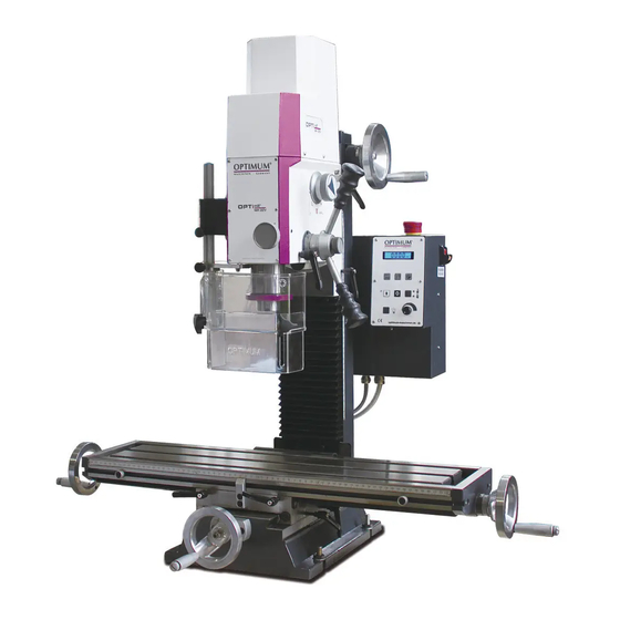
- Page 1 Operating Manual Version 1.0.4 Milling machine Part no. 3338135 Part no. 3338136 MH22V...
-
Page 2: Table Of Contents
Table of contents Safety Rating plates..............................5 Safety instructions (warning notes)........................ 6 1.2.1 Classification of hazards ........................6 1.2.2 Other pictograms..........................6 Intended use ..............................7 Reasonably foreseeable misuse........................8 1.4.1 Avoiding misuse ..........................8 Possible dangers posed by the milling machine.................... 9 Qualification .............................. - Page 3 4.7.1 Selecting the speed ........................29 4.7.2 Gear stage ............................30 Direction of spindle rotation ..........................30 Feed ................................30 4.10 Spindle quill feed ............................30 4.11 Inserting or Removing Tool ..........................31 4.11.1 Inserting ............................31 4.11.2 Removing............................31 4.12 Clamping the workpieces ..........................32 4.12.1 Calculation of the Cutting Forces or Necessary Holding Force when Milling .........32 4.13 Swivelling the milling head ...........................33 4.14...
- Page 4 Dear customer, Thank you very much for purchasing a product made by OPTIMUM. OPTIMUM metal working machines offer a maximum of quality, technically optimum solutions and convince by an outstanding price performance ratio. Continuous enhancements and product innovations guarantee state-of-the-art products and safety at any time.
-
Page 5: Safety
Safety Glossary of symbols provides further instructions calls on you to act listings This part of the operating instructions explains the meaning and use of the warning notes included in these operating instructions, defines the intended use of the milling machine, ... -
Page 6: Safety Instructions (Warning Notes)
INFORMATION If you are unable to rectify an issue using these operating instructions, please contact us for advice: Optimum Maschinen Germany GmbH Dr. Robert-Pfleger-Str. 26 D-96103 Hallstadt, Germany Email: info@optimum-maschinen.de Safety instructions (warning notes) 1.2.1 Classification of hazards We classify the safety warnings into different categories. The table below gives an overview of the classification of symbols (ideogram) and the warning signs for each specific danger and its (possible) consequences. -
Page 7: Intended Use
To securely fasten the tool, only tapers with a taper ratio of 7:24 with the collet chuck supplied for the BT20 spindle from Optimum Maschinen Germany are to be used. Using this drilling-milling machine it is possible to perform dry processing as well as processing by using cooling lubricants. -
Page 8: Reasonably Foreseeable Misuse
We expressly point out that the guarantee will expire, if any constructive, technical or proce- dural changes are not performed by the company Optimum Maschinen Germany GmbH. It is also part of the intended use that you observe the limits of the milling machine, ... -
Page 9: Possible Dangers Posed By The Milling Machine
WARNING! Risk of injury caused by flying workpieces. Clamp the workpiece in the machine vice. Make sure that the workpiece is firmly clamped in the machine vice and that the machine vice is firmly clamped onto the machine table. Use cooling and lubricating agents to increase the durability of the tool and to improve the ... -
Page 10: Qualification
WARNING! The milling machine may only be used with fully functional safety devices. Disconnect the milling machine immediately, whenever you detect a failure in the safety devices or when they are not fitted! All additional devices installed by the operator must be equipped with the stipulated safety devices. -
Page 11: Authorized Personnel
trained for the working environment, in which they are working and know the relevant standards and regulations. Qualified personnel Due to their professional training, knowledge and experience as well as knowledge of relevant regulations, qualified personnel are able to perform the assigned tasks and to independently recognise and avoid any possible dangers. -
Page 12: 1.6.7 Additional Requirements Regarding Qualification
1.6.7 Additional requirements regarding qualification The following additional requirements apply for work on electrical components or equipment: They must only be performed by a qualified electrician or person working under the instruc- tions and supervision of a qualified electrician. Before starting work on electrical parts or operating agents, the following actions must be taken in the order given: ... -
Page 13: Emergency Stop Button
1.9.1 Emergency stop button CAUTION! Only press the emergency stop button in a genuine emergency. Do not use the emergency stop button to stop the machine during normal operation. CAUTION! The spindle continues to rotate for a while, depending on the moment of Emergency stop inertia of the spindle and the tool in push button... -
Page 14: 1.9.3 Main Switch
1.9.3 Main switch WARNING! Dangerous voltage even if the main switch is switched off. The areas marked by the pictogram might contain live parts, even if the main switch is switched off. Switch off the milling machine with the main switch and lock it so it cannot be activated by unauthorised personnel or switched on by accident. -
Page 15: Personal Protective Equipment
1.11 Personal protective equipment For certain work, personal protective equipment is required. Protect your face and your eyes: Wear a safety helmet with facial protection when performing work where your face and eyes are exposed to hazards. Wear protective gloves when handling pieces with sharp edges. Wear safety shoes when you assemble, disassemble or transport heavy components. -
Page 16: Symbols On The Milling Machine
1.14 Symbols on the milling machine Make sure that the mandatory and warning symbols are legible. 1.15 Electronics Craftsman or industrial use Have the machine and/or the electric equipment checked regularly. Immediately eliminate all defects such as loose connections, defective wires, etc. A second person must be present during work on live components to disconnect the power in the event of an emergency. -
Page 17: Technical Specification
Ø 12 (Possible usable size with BT20) Spindle seat Spindle seat BT20 + 7:24 tool shank Pull stud BT20 (Optimum) Kegel / Taper 7:24 (SK20) Spannzange / Collet Anzugsbolzen / Pull stud Maximum distance between spindle nose - milling table [mm]... -
Page 18: Milling Table
Milling table Table length [mm] Table width [mm] Max. bearing load 50 kg T-slot size/distance/number 12 / 63 / 3 X axis travel [mm] Y axis travel [mm] Dimensions Fastening to the Machine Base on page 24 Total weight [kg] Work area Keep a work area of at least one metre around the machine free for operation and maintenance. -
Page 19: Emissions
Gear Mobilgrease OGL 007 or, Mobilux EP 004 or Mobil XHP, Bare steel parts acid-free oil, e.g. weapon oil, motor oil 2.11 Emissions Maximum sound pressure level at 1 m distance from 74 dB(A) - 80 dB(A) the machine and 1.60 m above the ground. Emission measurement Measurement in operating conditions in accordance with DIN ISO 8525 with surface areas Measurement methods in accordance with DIN 45635. -
Page 20: Dimensions
2.12 Dimensions MH22V│MH22VD Translation of original instruction Version 1.0.4 - 2020-07-28... -
Page 21: Delivery, Interdepartmental Transport, Assembly And Commissioning
Delivery, interdepartmental transport, assembly and commissioning Notes on transport, installation, commissioning Improper transport, installation and commissioning is liable to accidents and can cause damage or malfunctions to the machine for which we do not assume any liability or guarantee. Transport the scope of delivery secured against shifting or tilting with a sufficiently dimen- sioned industrial truck or a crane to the installation site. -
Page 22: Delivery
Delivery INFORMATION The machine is pre assembled. It is delivered in a transport box. After the unpacking and the transportation to the installation site it is necessary to mount and assemble the individual components of the machine. Check the status of the machine immediately upon receipt and claim possible damages at the last carrier also if the packing is not being damaged. -
Page 23: Assembly
Lock all clamping levers on the drilling-milling machine before you lift it. Make sure that no add-on pieces or varnished parts are damaged due to the load suspen- sion. Take care with the centre of gravity of the machine. Centre of gravity 3.5.1 Assembly... -
Page 24: Fastening To The Machine Base
The use of improper tool holders or their operation at inadmissible speeds constitutes a hazard. Only use the tool holders (e.g. drill chuck) which were delivered with the machine or which are offered as optional equipment by OPTIMUM. MH22V│MH22VD Translation of original instruction... -
Page 25: Electrical Connection
Only use tool holders in the intended admissible speed range. Tool holders may only be modified in compliance with the recommendation of OPTIMUM or the clamping device manufacturer. Electrical connection CAUTION! Arrange the machine's connection cable in such a way that it will not cause a tripping hazard. -
Page 26: 3.8.1 Cleaning And Lubrication
The milling machine has been painted with varnish. This fact must be taken into account when selecting your cooling lubricant. Optimum Maschinen Germany GmbH does not accept any lia- bility for subsequent damages due to unsuitable cooling lubricants. The flashpoint of the emul- sion must be higher than 140°C. -
Page 27: Optional Machine Base
3.10 Optional machine base Fixing points Mounting surface machine on the ground MH22V│MH22VD Version 1.0.4 - 2020-07-28 Translation of original instruction... -
Page 28: Operation
Operation Control and indicating elements Item Designation Item Designation Control panel Gear switch Quill lever Spindle protection Emergency stop switch Milling head height adjustment hand crank Mechanical securing, quick clamping system Milling table Display Clamping lever • Depth display or speed display Switching over display Switching over display •... -
Page 29: Safety
Safety The milling machine must only be operated under the following conditions: The milling machine is in proper working order. The milling machine is used as intended. The operating instructions are followed. All safety devices are installed and activated. ... -
Page 30: Gear Stage
4.7.2 Gear stage Changing the gear stage may only be at a standstill. Direction of spindle rotation A change in the direction of rotation at the MH22V is only possible if the spindle rotates even in its standard direction of rotation. The standard direction of rotation is clockwise. Feed with the hand cranks on the milling table. -
Page 31: Inserting Or Removing Tool
MH22V are listed. Screw the collet chuck BT20 from Optimum into the conical seat. Clean seat in the milling spindle. ... -
Page 32: Clamping The Workpieces
4.12 Clamping the workpieces CAUTION! Injuries can be caused by parts flying off. The workpiece must always be secured to the milling table in a machine vice, chuck or with another suitable clamping tool, such as a workholding device (clamping claws). Parallel Underlying plates Dividing device 3356200 + Chuck flange 3356254... -
Page 33: Swivelling The Milling Head
4.13 Swivelling the milling head The milling head can be swivelled to the right and to the left. Loosen the fastening screw on the milling head. Turn the drill-mill head to the desired position. Retighten the fastening screw. INFORMATION The milling head should be aligned after resetting to the initial position with a dial indicator so that holes can be produced with the spindle sleeve at a right angle. -
Page 34: Operation Dro5
4.14 Operation DRO5 Display: three position display, one speed display Counting resolution setting function Counting direction setting Linear error compensation Metric / inches change-over LCD display status setting Speed mode setting Basic value setting ... -
Page 35: 4.14.4 The Main Menu
4.14.4 The main menu In the normal display state, press and hold the "PROG" key for three seconds to enter the main menu. LCD display setting LCD display setting: the secondary menu, press "PROG" key to enter to modify the LED dis- play parameter. -
Page 36: 4.14.6 Parameter Setting Of X Y Z-Axis And Speed Axis
4.14.6 Parameter setting of X Y Z-axis and speed axis X-axis parameter Three-level menu, press "PROG" key to enter to modify the X-axis parameter. Y-axis parameter Three-level menu, press "PROG" key to enter to modify the Y-axis parameter. Z-axis parameter Three-level menu, press "PROG"... -
Page 37: Maintenance
Maintenance In this chapter you will find important information about Inspection Maintenance Repair of the milling machine. ATTENTION! Properly performed regular maintenance is an essential prerequisite for operational safety, failure-free operation, a long working life of the milling machine and ... -
Page 38: Inspection And Maintenance
Inspection and maintenance The type and level of wear depends to a large extent on the individual usage and operating conditions. Any indicated intervals therefore are only valid for the corresponding approved con- ditions. Interval Where? What? How? Safety check on page 14 Start of work, after every main-... - Page 39 Interval Where? What? How? An larger amount of backlash in the milling head spindle can be reduced by adjusting the spindle nut. The spindle nut is reset by reducing the thread flanks of the spindle nut with take- up screws. After the reset, it is necessary to check if there is still smooth movement over the entire path, otherwise wear is considerably increased due to friction between the spindle nut and the spindle.
- Page 40 Interval Where? What? How? Increased play in the milling table spindles can be reduced by resetting the spindle nuts. The spindle nuts are reset by reduc- ing the thread flanks of the spindle nut by means of take-up screws. After the reset, it is necessary to check if there is still smooth movement over the entire path, otherwise wear is con- siderably increased due to friction between the spindle nut and the spindle.
-
Page 41: Repair
If the repairs are carried out by qualified technical personnel, they must follow the indications given in these operating instructions. Optimum Maschinen Germany GmbH accepts no liability nor does it guarantee against damage and operating malfunctions resulting from failure to observe these operating instructions. -
Page 42: Setting Instructions Control Board
5.3.2 Setting instructions control board Please find below a description to set the operating parameters, if required after replacement of the control and of the motor. Vmax This is the potentiometer to set the maximum possible speed of the motor. The speed of 3000 min must not be exceeded since the spindle bearings and your tools might get damaged. - Page 43 Potentiometer Measuring points Setting value Measuring range min. 1 M Ohm Only approximate value, perform setting via speed control measuring point 3 measuring point 1 measuring point 2 + 12V measuring point 4 TU1503V | TU2004V | TU2304V | Version 1.0.4 - 2020-7-28 Original operating instructions...
- Page 44 Setting CL Setting Torque Setting Acel TU1503V | TU2004V | TU2304V | Original operating instructions Version 1.0.4 - 2020-7-28...
-
Page 45: Ersatzteile - Spare Parts
Ersatzteile - Spare parts Ersatzteilbestellung - Ordering spare parts Bitte geben Sie folgendes an - Please indicate the following : Seriennummer - Serial No. Maschinenbezeichnung - Machines name Herstellungsdatum - Date of manufacture Artikelnummer - Article no. ... -
Page 46: Fräsfutterschutz - Mill Chuck Safety
Fräsfutterschutz - Mill chuck safety Img.6-1: Fräsfutterschutz - Mill chuck safety DE | EN MH22V Originalbetriebsanleitung Version 1.0.4 - 2020-7-28... -
Page 47: Fräskopf - Milling Head
Fräskopf - Milling head Img.6-2: Fräskopf - Milling head MH22V DE | EN Version 1.0.4 - 2020-7-28 Originalbetriebsanleitung... -
Page 48: Fräskopf - Milling Head
Fräskopf - Milling head Img.6-3: Fräskopf - Milling head DE | EN MH22V Originalbetriebsanleitung Version 1.0.4 - 2020-7-28... -
Page 49: Kreuztisch - Cross Table
Kreuztisch - Cross table Img.6-4: Kreuztisch - Cross table MH22V DE | EN Version 1.0.4 - 2020-7-28 Originalbetriebsanleitung... -
Page 50: Säule - Column
6.10 Säule - Column Img.6-5: Säule - Column DE | EN MH22V Originalbetriebsanleitung Version 1.0.4 - 2020-7-28... -
Page 51: Schaltbox - Switch Box
6.11 Schaltbox - Switch box Img.6-6: Schaltbox - Switch box MH22V DE | EN Version 1.0.4 - 2020-7-28 Originalbetriebsanleitung... -
Page 52: Maschinenschilder - Machine Labels
6.12 Maschinenschilder - Machine labels Abb.6-7: Maschinenschilder - Machine labels DE | EN MH22V Originalbetriebsanleitung Version 1.0.4 - 2020-7-28... -
Page 53: Schaltplan - Wiring Diagram
6.13 Schaltplan - Wiring diagram MH22V DE | EN Version 1.0.4 - 2020-7-28 Originalbetriebsanleitung... - Page 54 DE | EN MH22V Originalbetriebsanleitung Version 1.0.4 - 2020-7-28...
- Page 55 MH22V DE | EN Version 1.0.4 - 2020-7-28 Originalbetriebsanleitung...
-
Page 56: Ersatzteilliste - Spare Parts List
6.14 Ersatzteilliste - Spare parts list Ersatzteileliste Fräsfutterschutz - Spare part list Drill chuck protection Menge Grösse Artikelnummer Bezeichnung Designation Qty. Size Item no. Gehäuse Housing Klemmschraube Clamping screw Mikroschalter Micro switch Platte Plate Platte Plate 033381351118 Aluprofil Aluminium profiles Klemmschraube Clamping screw Fräsfutterschutz... - Page 57 Handhebel Handle lever 03338135128 Innensechskantschraube Socket head screw ISO 4762 - M5 x 10 Klemmhebel Clamping lever 03338135130 Messingstift Brass pin Innensechskantschraube Socket head screw ISO 4762 - M3 x 8 Innensechskantschraube Socket head screw ISO 4762 - M6 x 12 Keilleiste 03338135134 Senkschraube...
- Page 58 Platte Plate Klemmhebel Clamping lever 03338135178 Welle Shaft 03338135179 Buchse Bushing 03338135181 Passfeder Fitting key DIN 6885 - A 4 x 4 x 12 042P4412 Zahnrad Gear 03338135183 Welle Shaft 03338135184 Ring Ring Flansch Flange 03338135186 Innensechskantschraube Socket head screw GB 70-85 - M4 x 10 Einstellknopf Ajust knob...
- Page 59 Lagerbock Bearing block 03338135202 Frästisch Mill table 03338135203 Buchse Bushing Block Block Lagerbock Bearing block 03338135206 Zeiger Indicator 03338135207 Spindelmutter Spindle nut 03338135208 Keilleiste 03338135209 Spindel Spindle 03338135210 Lagerbock Bearing block 03338135211 Spindel Spindle 03338135212 Spindelmutter Spindle nut 03338135213 Keilleiste 03338135214 Anschluss Plug...
- Page 60 Abdeckung Cover 03338135302 Lagerbock Bearing block 03338135303 Spindel Spindle 03338135304 Kegelrad Bevel gear 03338135305 Kagelrad Bevel gear 03338135306 Buchse Bushing Skala Scale 03338135308 Flansch Flange 03338135309 Skalenring Scale ring 03338135310 Welle Shaft 03338135311 Handrad Handle 03338135312 Hülse Sleeve 03338135313 Ring Ring Kugellager Ball bearing...
- Page 61 Sicherheitsschild Safety lable Sicherheitsschild Safety lable Ersatzteileliste Elektrik - Spare parts list electronics Menge Grösse Artikelnummer Bezeichnung Designation Qty. Size Item no. Netzfilter Line filter Hauptschalter Main switch Not-Halt Schalter Emergency-stop button Sicherheitsschalter Safety switch for chuck Fräsfutterschutz protection Steuerkarte 608B Control board 608B Antriebsmotor Drive motor...
-
Page 62: Malfunctions
Malfunctions Milling machine malfunctions Cause/ Malfunction Solution possible effects Tool "burnt". • Incorrect speed. • Choose a different speed, excessive feed. • Chips are not coming out of the • Withdraw the tool more frequently. drilled hole. • Blunt tool. •... -
Page 63: Appendix 8.1 Copyright
Appendix Copyright This document is protected by copyright. All derived rights are reserved, especially those of translation, re-printing, use of figures, broadcast, reproduction by photo-mechanical or similar means and recording in data processing systems, either partial or total. Subject to technical changes without notice. Terminology/Glossary Term Explanation... -
Page 64: Liability Claims/Warranty
Non reproducible software errors Any services, which OPTIMUM GmbH or one of its agents performs in order to fulfil any addi- tional warranty are neither an acceptance of the defects nor an acceptance of its obligation to compensate. These services neither delay nor interrupt the warranty period. -
Page 65: Storage
Example: not stackable - do not stack further packing case on top of the first one. Consult Optimum Maschinen Germany GmbH if the machine and accessories are stored for more than three months or are stored under different environmental conditions than those spec- ified here. -
Page 66: Decommissioning
8.7.1 Decommissioning CAUTION! Disused equipment must be decommissioned in a professional manner in order to avoid later misuse and danger the environment or persons. Disassemble the machine if required into easy-to-handle and reusable assemblies and component parts. Dispose of machine components and operating fluids using the intended disposal methods. -
Page 67: Disposal Via Municipal Collection Facilities
Modified settings Any experiences with the machine which might be important for other users Recurring malfunctions Optimum Maschinen Germany GmbH Dr.-Robert-Pfleger-Str. 26 D-96103 Hallstadt, Germany Fax +49 (0) 951 - 96 555 - 888 email: info@optimum-maschinen.de MH22V│MH22VD Version 1.0.4 - 2020-07-28... - Page 68 MH22V│MH22VD Translation of original instruction Version 1.0.4 - 2020-07-28...
- Page 69 EC Declaration of Conformity according to Machinery directive 2006/42/EC, Annex II 1.A Optimum Maschinen Germany GmbH The manufacturer / distributor Dr.-Robert-Pfleger-Str. 26 D - 96103 Hallstadt, Germany hereby declares that the following product Hand-controlled milling machine Product designation: MH22V ; MH22VD...
- Page 70 Index Installation site ..........22 Restoring Assembly .............. 23 readiness for operation ........29 Cleaning and lubrication ........25 Safety Connection instructions ............6 electrical ............25 Service Hotline ............45 Copyright .............. 63 Spare parts Hotline ..........45 Customer service ..........41 Specialist dealer ...........41 Customer service technician ........
- Page 71 Quellenverzeichnis von Ihrem Fachhändler Metallbau Mehner Optimum Fräsmaschinen und CNC Fräsmaschinen: Optimum OPTImill MH22 Übersicht OPTImill MH 22 V / MH 22 VD • ◦ OPTImill MH 22 Ersatzteile ◦ OPTImill MH 22 Zubehör CNC OPTImill MH 22 V / MH 22 VD •...
Need help?
Do you have a question about the OPTImill MH 22V and is the answer not in the manual?
Questions and answers