
Related Manuals for Optimum Optimill MH 20V


Summary of Contents for Optimum Optimill MH 20V
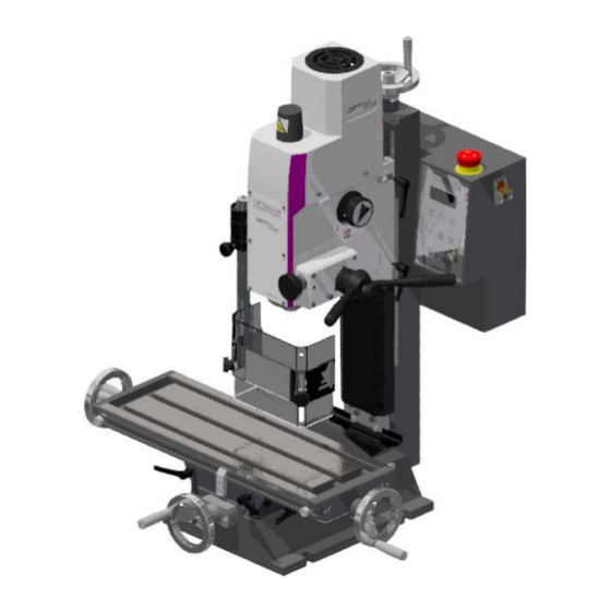
- Page 1 Operating Manual Version 2.5.1 Milling machine Part no. 3338131 MH 20VL Part no. 3338132 MH 20VLD Part no. 3338133...
-
Page 2: Table Of Contents
Table of contents Safety Type plate ..............................6 Safety instructions (warning notes)........................ 7 1.2.1 Classification of hazards ........................7 1.2.2 Other pictograms..........................7 Intended use ..............................8 Reasonably foreseeable misuse........................9 1.4.1 Avoiding misuse ..........................9 Possible dangers posed by the milling machine..................10 Qualification .............................. - Page 3 3.11 Optional digital display DRO5 ........................28 Operation Control and indicating elements ........................29 Safety ................................30 Switching the milling machine on .........................30 Switching off the drilling milling machine ......................30 Resetting an emergency stop situation ......................30 Power failure, Restoring readiness for operation ..................30 Speed setting ...............................30 4.7.1 Selecting the speed ........................30...
- Page 4 8.7.1 Decommissioning........................... 68 8.7.2 Dismantling ............................ 68 8.7.3 Disassembly........................... 68 8.7.4 Packing and loading........................68 Disposal of new device packaging....................... 68 Disposal of lubricants and cooling lubricants....................68 8.10 Disposal via municipal collection facilities ....................69 8.11 Product follow-up ............................69 MH20V | MH20VL | MH20VLD Translation of original instructions Version 2.5.1 - 2020-07-28...
- Page 5 Dear customer, Thank you very much for purchasing a product made by OPTIMUM. OPTIMUM metal working machines offer a maximum of quality, technically optimum solutions and convince by an outstanding price performance ratio. Continuous enhancements and product innovations guarantee state-of-the-art products and safety at any time.
-
Page 6: Safety
Safety Glossary of symbols provides further instructions calls on you to act listings This part of the operating instructions explains the meaning and use of the warning notes included in these operating instructions, defines the intended use of the milling machine, ... -
Page 7: Safety Instructions (Warning Notes)
INFORMATION If you are unable to rectify an issue using these operating instructions, please contact us for advice: Optimum Maschinen Germany GmbH Dr. Robert-Pfleger-Str. 26 D-96103 Hallstadt, Germany Email: info@optimum-maschinen.de Safety instructions (warning notes) 1.2.1 Classification of hazards We classify the safety warnings into different categories. The table below gives an overview of the classification of symbols (ideogram) and the warning signs for each specific danger and its (possible) consequences. -
Page 8: Intended Use
The milling machine must neither be renovated nor modified in any other way. If the milling machine is used in any way other than described above, or modified without the approval of Optimum Maschinen Germany GmbH, then the milling machine is being used improperly. -
Page 9: Reasonably Foreseeable Misuse
We expressly point out that the guarantee will expire, if any constructive, technical or proce- dural changes are not performed by the company Optimum Maschinen Germany GmbH. It is also part of the intended use that you observe the limits of the milling machine, ... -
Page 10: Possible Dangers Posed By The Milling Machine
Clamp the cutting tools and workpieces on clean clamping surfaces. Sufficiently lubricate the machine. Set the bearing clearance and guides correctly. Recommendations: Insert the drill in a way that it is positioned exactly between the three clamping jaws of the ... -
Page 11: Qualification
All additional devices installed by the operator must be equipped with the stipulated safety devices. This is your responsibility being the operating company or private user! "Safety devices“ on page 13 Qualification It is indispensable that the operator is suitably qualified for safe use and secure setting and operation of the machine. -
Page 12: Authorized Personnel
Qualified personnel Due to their professional training, knowledge and experience as well as knowledge of relevant regulations, qualified personnel are able to perform the assigned tasks and to independently recognise and avoid any possible dangers. Instructed person Instructed persons were instructed by the operating company regarding the assigned tasks and any possible risks of improper behaviour. -
Page 13: Additional Requirements Regarding Qualification
1.6.7 Additional requirements regarding qualification The following additional requirements apply for work on electrical components or equipment: They must only be performed by a qualified electrician or person working under the instruc- tions and supervision of a qualified electrician. Before starting work on electrical parts or operating agents, the following actions must be taken in the order given: ... -
Page 14: Emergency Stop Button
1.9.1 Emergency stop button CAUTION! Only press the emergency stop button (1) in a genuine emergency. Do not use the emergency stop button to stop the machine during normal operation. CAUTION! The spindle continues to rotate for a while, depending on the moment of inertia of the spindle and the tool in use. -
Page 15: Main Switch
1.9.3 Main switch WARNING! Dangerous voltage even if the main switch is switched off. The areas marked by the pictogram might contain live parts, even if the main switch is switched off. Switch off the milling machine with the main switch (3) and lock it so it cannot be acti- vated unauthorised... -
Page 16: Personal Protective Equipment
1.11 Personal protective equipment For certain work, personal protective equipment is required. Protect your face and your eyes: Wear a safety helmet with facial protection when performing work where your face and eyes are exposed to hazards. Wear protective gloves when handling pieces with sharp edges. Wear safety shoes when you assemble, disassemble or transport heavy components. -
Page 17: Using Lifting Equipment
1.13 Using lifting equipment WARNING! The use of unstable lifting and load suspension equipment that might break under load can cause severe injuries or even death. Check to ensure that the lifting and load-suspension equipment are of sufficient load- bearing capability and are in perfect condition. Observe the accident prevention regulations issued by your Employers Liability Insurance Association or other supervisory authorities applicable to your company. -
Page 18: Technical Specification
Technical specification The following information represents the dimensions and indications of weight and the manu- facturer‘s approved machine data. Electrical connection 230V ~ 50Hz ~ 60Hz Milling spindle motor power 750 W Milling capacity Drilling capacity in steel (S235JR) [mm] Ø... -
Page 19: Milling Table
Milling table 507 ~ 698 Table length C MH20V / MH20VL(D) [mm] 474 / 675 Table width [mm] Maximum load capacity MH20V / MH20VL(D) 50 kg / 40 kg T-slot size/distance/number 12 / 63 / 3 X axis travel MH20V / MH20VL(D) [mm] 280 / 480 Y axis travel [mm] Dimensions... -
Page 20: Operating Material
Admissible relative humidity 25-80% Environmental conditions - storage -5°~45° 2.10 Operating material Gear Mobilgrease OGL 007 or, Mobilux EP 004 or Mobil XHP, Bare steel parts acid-free oil, e.g. weapon oil, motor oil 2.11 Emissions Maximum sound pressure level at 1 m distance from 74 dB(A) - 80 dB(A) the machine and 1.60 m above the ground. -
Page 21: Dimensions
2.12 Dimensions MH20V MH20VL(D) 950 MH20V MH20VL(D) 700 MH20V | MH20VL | MH20VLD Version 2.5.1 - 2020-07-28 Translation of original instructions... - Page 22 MH20V | MH20VL | MH20VLD Translation of original instructions Version 2.5.1 - 2020-07-28...
-
Page 23: Delivery, Interdepartmental Transport, Assembly And Commissioning
Delivery, interdepartmental transport, assembly and commissioning Notes on transport, installation, commissioning Improper transport, installation and commissioning is liable to accidents and can cause damage or malfunctions to the machine for which we do not assume any liability or guarantee. Transport the scope of delivery secured against shifting or tilting with a sufficiently dimen- sioned industrial truck or a crane to the installation site. -
Page 24: Delivery
Delivery INFORMATION The machine is pre assembled. It is delivered in a transport box. After the unpacking and the transportation to the installation site it is necessary to mount and assemble the individual components of the machine. Check the status of the machine immediately upon receipt and claim possible damages at the last carrier also if the packing is not being damaged. -
Page 25: Lifting The Machine
Lifting the machine WARNING! Danger of crushing and overturning. Proceed carefully when lifting, installing and assembling the machine. Fix the load lifting gear around the drilling-milling head. Use a lifting strap with a width of 30 mm to do this. ... -
Page 26: Fastening To The Machine Base
ATTENTION! Inadequate rigidity of the foundation will cause interaction of vibrations between the milling machine and the foundation (resonant frequency of the components). If the rigidity of the overall system is insufficient, critical speeds with annoying vibrations will be reached very quickly and lead to bad milling results. ... -
Page 27: First Commissioning
Only use the tool holders (e.g. drill chuck) which were delivered with the machine or which are offered as optional equipment by OPTIMUM. Only use tool holders in the intended admissible speed range. Tool holders may only be modified in compliance with the recommendation of OPTIMUM or the clamping device manufacturer. Electrical connection... -
Page 28: Optional Machine Base
3.10 Optional machine base MSM1 - Item no. 3353000 Fixing points Mounting surface machine on the ground 3.11 Optional digital display DRO5 The optionally available digital display DRO5 can be attached to the side of the control panel with screws. The holes are already drilled there from 2021 onwards. The magnetic holder of the DRO5 included in the scope of delivery is not strong enough to fix the display securely to the control panel. -
Page 29: Operation
Operation Control and indicating elements Pos. Designation Item Designation Control panel Gear switch Spindle sleeve lever Spindle guard Emergency stop button Milling head height adjustment hand crank Spindle protection clamping screw Cross table Display Clamping lever, Clamping screws • Depth display or speed display Switching over display Switching over display •... -
Page 30: Safety
Safety The milling machine must only be operated under the following conditions: The milling machine is in proper working order. The milling machine is used as intended. The operating instructions are followed. All safety devices are installed and activated. ... -
Page 31: Gear Stage
4.7.2 Gear stage Changing the gear stage may only be at a standstill. Direction of spindle rotation A change in the direction of rotation at the MH22V is only possible if the spindle rotates even in its standard direction of rotation. The standard direction of rotation is clockwise. Feed with the hand cranks on the milling table. -
Page 32: 4.10.2 Removing
Screw the draw bar in the tool. Tighten the tool with the draw bar and Draw bar hold the spindle on the counter bear- ing by means of a wrench. Steady/ Counter-bearing Img.4-2: Drill-mill head 4.10.2 Removing Hold the spindle on counter bearing with a wrench and loosen the draw bar. -
Page 33: Clamping The Workpieces
4.11 Clamping the workpieces CAUTION! Injuries can be caused by parts flying off. The workpiece must always be secured to the milling table in a machine vice, chuck or with another suitable clamping tool, such as a workholding device (clamping claws). Parallel Underlying plates Workholding device 3352032... -
Page 34: Swivelling The Milling Head
4.12 Swivelling the milling head The milling head can be swivelled to the right and to the left. Loosen the fastening screw on the milling head. Turn the drill-mill head to the desired position. Retighten the fastening screw. INFORMATION The milling head should be aligned after resetting to the initial position with a dial indicator so that holes can be produced with the spindle sleeve at a right angle. -
Page 35: Operation Dro5
4.14 Operation DRO5 Display: three position display, one speed display Counting resolution setting function Counting direction setting Linear error compensation Metric / inches change-over LCD display status setting Speed mode setting Basic value setting ... -
Page 36: 4.14.4 The Main Menu
4.14.4 The main menu In the normal display state, press and hold the "PROG" key for three seconds to enter the main menu. LCD display setting LCD display setting: the secondary menu, press "PROG" key to enter to modify the LED dis- play parameter. -
Page 37: 4.14.6 Parameter Setting Of X Y Z-Axis And Speed Axis
4.14.6 Parameter setting of X Y Z-axis and speed axis X-axis parameter Three-level menu, press "PROG" key to enter to modify the X-axis parameter. Y-axis parameter Three-level menu, press "PROG" key to enter to modify the Y-axis parameter. Z-axis parameter Three-level menu, press "PROG"... -
Page 38: Maintenance
Maintenance In this chapter you will find important information about Inspection Maintenance Repair of the milling machine. ATTENTION! Properly performed regular maintenance is an essential prerequisite for operational safety, failure-free operation, a long working life of the milling machine and ... - Page 39 Interval Where? What? How? "Safety check“ on page 15 Start of work, after every maintenance or repair work Oil all guide rails. Start of work, after every Oiling maintenance or repair work Oil all bare steel surfaces. Use acid-free oil. Every week Oiling ...
- Page 40 Interval Where? What? How? An larger amount of backlash in the milling head spindle can be reduced by adjusting the spindle nut. The spindle nut is reset by reducing the thread flanks of the spindle nut with take- up screws. After the reset, it is necessary to check if there is still smooth movement over the entire path, otherwise wear is considerably increased due to friction between the spindle nut and the spindle.
- Page 41 Interval Where? What? How? Increased play in the milling table spindles can be reduced by resetting the spindle nuts. The spindle nuts are reset by reduc- ing the thread flanks of the spindle nut by means of take-up screws. After the reset, it is necessary to check if there is still smooth movement over the entire path, otherwise wear is con- siderably increased due to friction between the spindle nut and the spindle.
- Page 42 Interval Where? What? How? "Operator's obligations“ on page 12 Electrical "Electronics“ on page 17 inspection MH20V | MH20VL | MH20VLD Translation of original instructions Version 2.5.1 - 2020-07-28...
-
Page 43: Repair
If the repairs are carried out by qualified technical personnel, they must follow the indications given in these operating instructions. Optimum Maschinen Germany GmbH accepts no liability nor does it guarantee against damage and operating malfunctions resulting from failure to observe these operating instructions. - Page 44 MH20V | MH20VL | MH20VLD Translation of original instructions Version 2.5.1 - 2020-07-28...
-
Page 45: Setting Instructions Control Board
5.3.2 Setting instructions control board Please find below a description to set the operating parameters, if required after replacement of the control and of the motor. Vmax This is the potentiometer to set the maximum possible speed of the motor. The speed of 3000 min must not be exceeded since the spindle bearings and your tools might get damaged. - Page 46 Potentiometer Measuring points Setting value Measuring range min. 1 M Ohm Only approximate value, perform setting via speed control measuring point 3 measuring point 1 measuring point 2 + 12V measuring point 4 TU1503V | TU2004V | TU2304V | Original operating instructions Version 2.5.1 - 2020-7-28...
- Page 47 Setting CL Setting Torque Setting Acel TU1503V | TU2004V | TU2304V | Version 2.5.1 - 2020-7-28 Original operating instructions...
-
Page 48: Ersatzteile - Spare Parts
Ersatzteile - Spare parts Ersatzteilbestellung - Ordering spare parts Bitte geben Sie folgendes an - Please indicate the following : Seriennummer - Serial No. Maschinenbezeichnung - Machines name Herstellungsdatum - Date of manufacture Artikelnummer - Article no. ... -
Page 49: Fräskopf - Milling Head
Fräskopf - Milling head 6-1: Fräskopf - Milling head MH20V | MH20VL | MH20VLD DE | GB Version 2.5.1 - 2020-7-28 Originalbetriebsanleitung... -
Page 50: Fräskopf - Milling Head
Fräskopf - Milling head 6-2: Fräskopf - Milling head DE | GB MH20V | MH20VL | MH20VLD Originalbetriebsanleitung Version 2.5.1 - 2020-7-28... - Page 51 Ersatzteileliste Fräskopf - Spare parts list mill head Menge Grösse Artikelnummer Pos. Bezeichnung Designation Qty. Size Item no. Kugellager Taper roller bearing 6002-2Z 0406002ZZ Welle Shaft 03338115105 Passfeder Fitting key DIN 6885 - A 5 x 5 x 50 042P5550 Sicherungsring Retaining ring DIN 472 - 32 x 1,2...
- Page 52 Flansch Flange 03338115151 Platte Plate 03338115152 Welle Shaft 03338115153 Schaltgabel Switch fork 03338115154 Gewindestift Grub screw ISO 4028 - M5 x 8 Wahlschalter Mode switch 03338115156 Gewindestift Grub screw ISO 4028 - M5 x 16 Gewindestift Grub screw ISO 4028 - M8 x 8 Stahlkugel Steel ball Feder...
- Page 53 Innensechskantschraube Socket head screw ISO 4762 - M3 x 12 Spindelmutter Spindle nut 033381151123 Gewindestift Grub screw ISO 4028 - M4 x 12 Zugentlastung Strain relief Platte Plate 033381151126 Drehzahlsensor Rotary speed sensor 033381151127 Halter Holder 033381151128 Abdeckung Cover 033381151129 Bushing pulse Buchse Signalgeber 033381151130...
-
Page 54: Kreuztisch - Cross Table
Kreuztisch - Cross table 6-3: Kreuztisch - Cross table DE | GB MH20V | MH20VL | MH20VLD Originalbetriebsanleitung Version 2.5.1 - 2020-7-28... - Page 55 Ersatzteileliste Kreuztisch - Spare parts list cross table Menge Grösse Artikelnummer Pos. Bezeichnung Designation Qty. Size Item no. Messingstift Brass pin 0333812014 Klemmhebel Adjust locating handle 0333812015 Schraube Keilleiste Gib screw 0333812016 Federstück Spring piece 0333812038 Gummi - Späneabdeckung Rubber splash guard 0333812023 Leiste Plate...
-
Page 56: Säule - Column
Säule - Column 6-4: Säule - Column Ersatzteileliste Säule - Spare parts list column Menge Grösse Artikelnummer Pos. Bezeichnung Designation Qty. Size Item no. Säule Column 03338115301 Lagerbock Bearing block 03338115302 Spindel Spindle 03338115303 Federring Spring ring DIN 128 - A6 Innensechskantschraube Socket head screw ISO 4762 - M6 x 20... -
Page 57: Schaltbox - Switch Box
Schraube Screw 03338115313 Innensechskantschraube Socket head screw ISO 4762 - M8 x 70 Skala Scale 03338115315 Federring Spring ring DIN 128 - A8 Gummiabdeckung Rubber cover 03338115317 Platte Plate 03338115318 Platte Plate 03338115319 Innensechskantschraube Socket head screw ISO 4762 - M5 x 10 Axiallager Thrust bearing 51200... -
Page 58: Fräsfutterschutz - Mill Chuck Safety
Fräsfutterschutz - Mill chuck safety 6-6: Fräsfutterschutz - Mill chuck safety Ersatzteileliste Fräsfutterschutz - Spare parts list milling chuck protection Menge Grösse Artikelnummer Pos. Bezeichnung Designation Qty. Size Item no. Führung Guide Klemmschraube Clamping screw Mikroschalter Micro switch Platte Plate Alustange Aluminium rod Futterschutz... -
Page 59: Maschinenschilder - Machine Labels
6.10 Maschinenschilder - Machine labels Abb.6-7: Maschinenschilder - Machine labels Ersatzteilliste Maschinenschilder - Spare part list machine labels Menge Grösse Artikelnummer Pos. Bezeichnung Designation Qty. Size Article no. Frontschild Front lable 03338115L01 Maschinenlabel Machine lable 03338115L02 Sicherheitsschild Safety lable 03338115L03 Sicherheitsschild Safety lable 03338115L04... -
Page 60: Schaltplan - Wiring Diagram
6.11 Schaltplan - Wiring diagram DE | GB MH20V | MH20VL | MH20VLD Originalbetriebsanleitung Version 2.5.1 - 2020-7-28... - Page 61 MH20V | MH20VL | MH20VLD DE | GB Version 2.5.1 - 2020-7-28 Originalbetriebsanleitung...
- Page 62 DE | GB MH20V | MH20VL | MH20VLD Originalbetriebsanleitung Version 2.5.1 - 2020-7-28...
- Page 63 Ersatzteileliste Elektrik - Spare parts list electrical components Menge Grösse Artikelnummer Pos. Bezeichnung Designation Qty. Size Item no. Netzfilter Line filter Hauptschalter Main switch Not-Halt Schalter Emergency-stop button Sicherheitsschalter Fräsfutterschutz Safety switch for chuck protection Steuerkarte 608B Control board 608B Antriebsmotor Drive motor 03338122221...
-
Page 64: Malfunctions
Malfunctions Milling machine malfunctions Cause/ Malfunction Solution possible effects Tool "burnt". • Incorrect speed. • Choose a different speed, excessive feed. • Chips are not coming out of the • Withdraw the tool more frequently. drilled hole. • Blunt tool. •... -
Page 65: Appendix 8.1 Copyright
Appendix Copyright This document is protected by copyright. All derived rights are reserved, especially those of translation, re-printing, use of figures, broadcast, reproduction by photo-mechanical or similar means and recording in data processing systems, either partial or total. Subject to technical changes without notice. Terminology/Glossary Term Explanation... -
Page 66: Liability Claims/Warranty
Non reproducible software errors Any services, which OPTIMUM GmbH or one of its agents performs in order to fulfil any addi- tional warranty are neither an acceptance of the defects nor an acceptance of its obligation to compensate. These services neither delay nor interrupt the warranty period. -
Page 67: Storage
Example: not stackable - do not stack further packing case on top of the first one. Consult Optimum Maschinen Germany GmbH if the machine and accessories are stored for more than three months or are stored under different environmental conditions than those spec- ified here. -
Page 68: Decommissioning
8.7.1 Decommissioning CAUTION! Disused equipment must be decommissioned in a professional manner in order to avoid later misuse and danger the environment or persons. Disassemble the machine if required into easy-to-handle and reusable assemblies and component parts. Dispose of machine components and operating fluids using the intended disposal methods. -
Page 69: Disposal Via Municipal Collection Facilities
Any experiences with the machine which might be important for other users Recurring malfunctions Optimum Maschinen Germany GmbH Dr.-Robert-Pfleger-Str. 26 D-96103 Hallstadt, Germany Fax +49 (0) 951 - 96 555 - 888 email: info@optimum-maschinen.de MH20V | MH20VL | MH20VLD Version 2.5.1 - 2020-07-28... - Page 70 EC Declaration of Conformity according to Machinery directive 2006/42/EC, Annex II 1.A Optimum Maschinen Germany GmbH The manufacturer / distributor Dr.-Robert-Pfleger-Str. 26 D - 96103 Hallstadt, Germany hereby declares that the following product Hand-controlled milling machine Product designation: MH20V │ MH20VL │ MH20VLD...
- Page 71 Index readiness for operation ........30 Assembly ..............25 Safety instructions ............7 Cleaning and lubrication ........27 Specialist dealer ........... 43 Collets ..............32 Speeds ..............19 Connection Spindle nut ............40 electrical ............27 Spindle seat ............18 Copyright ...............65 Spindle sleeve feed ..........31 Customer service ..........43 Switching off ............
- Page 72 Quellenverzeichnis von Ihrem Fachhändler Metallbau Mehner Optimum Fräsmaschinen und CNC Fräsmaschinen: Optimum OPTImill MH20 Übersicht OPTImill MH 20 V / MH 20 VL / MH 20 VLD • ◦ OPTImill MH 20 Ersatzteile ◦ OPTImill MH 20 Zubehör CNC OPTImill MH 20 V / MH 20 VL / MH 20 VLD •...
Need help?
Do you have a question about the Optimill MH 20V and is the answer not in the manual?
Questions and answers