Table of Contents
Advertisement
Quick Links
KEEP FOR FUTURE REFERENCE
INSTRUCTIONS
International Version
P.O. Box 368 – 908 West Main
Laurel, MT USA 59044
MODEL NUMBERS: N4950AIR, N10TAIR
phone 800-548-7341
phone 406-628-8231
SERIAL NUMBER: ___________
fax 406-628-8354
(please see serial label and record number here)
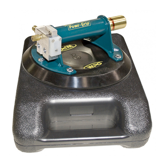
HAND-HELD VACUUM CUP
AIR-POWERED
READ ALL INSTRUCTIONS AND WARNINGS
BEFORE OPERATING THIS HAND CUP
DESIGNED FOR THE MATERIALS HANDLING PROFESSIONAL
Advertisement
Table of Contents

Related Manuals for WPG N4950AIR


Summary of Contents for WPG N4950AIR
- Page 1 KEEP FOR FUTURE REFERENCE INSTRUCTIONS International Version P.O. Box 368 – 908 West Main Laurel, MT USA 59044 MODEL NUMBERS: N4950AIR, N10TAIR phone 800-548-7341 phone 406-628-8231 SERIAL NUMBER: ___________ fax 406-628-8354 (please see serial label and record number here) HAND-HELD VACUUM CUP...
-
Page 3: Table Of Contents
TABLE OF CONTENTS SPECIFICATIONS ......................2 WARNINGS ........................3 OPERATING FEATURES ....................4 ASSEMBLY ........................5 INTENDED USE ....................... 6 ......................6 HARACTERISTICS ......................7 PERATING NVIRONMENT ....................... 7 ISPOSAL OF THE OPERATION ........................8 ..................... 8 EFORE SING THE Taking Safety Precautions .......................... -
Page 4: Specifications
Designed for use with a compressed air supply, these N-Series hand cups employ vacuum for attaching to loads, which are manually lifted and carried, offering a wide range of handling options. Model Number: N4950AIR N10TAIR Vacuum Pad / Pad Spread: 8" [20 cm] nominal diameter 10"... -
Page 5: Warnings
WARNINGS Powr-Grip is pleased to offer the most reliable hand-held vacuum cups available. Despite the high degree of security provided by this product, certain precautions must be observed to protect the operator and others. Always wear personal protective equipment that is appropriate for the material being handled. Follow trade association guidelines. -
Page 6: Operating Features
OPERATING FEATURES Note: Components featured in the following instructions for assembling, operating or maintaining the hand-held vacuum cup are underlined on their first appearance in each section. Standard N4950AIR shown. 1) VACUUM PAD 5) VACUUM RELEASE BUTTON 2) PLUNGER 6) VACUUM PUMP (VENTURI) 3) RED-LINE VACUUM INDICATOR 7) 1/8"... -
Page 7: Assembly
ASSEMBLY 1) Remove the hand-held vacuum cup from its carrying case or remove the pad cover, depending on the model. Save the case or cover for use whenever the hand cup is transported or stored. 2) Connect the hand cup's vacuum pump to an appropriate compressed air supply (see SPECIFICATIONS: Power Source), as follows: Use appropriate hose and/or fittings to connect an air line from the compressed air supply to the 1/8"... -
Page 8: Intended Use
INTENDED USE HARACTERISTICS WARNING: This hand cup is NOT intended for lifting hazardous materials, such as explosives or radioactive substances. The operator must verify that the hand cup is intended to handle each load, in accordance with the following requirements: •... -
Page 9: Operating Environment
PERATING NVIRONMENT The operator must determine whether the hand cup is intended to be used in each work environment, in accordance with the following restrictions: WARNING: Never use hand cup in dangerous environments. • This hand cup is not intended for use in any environment that is inherently dangerous to the operator or likely to compromise the hand cup's ability to function. -
Page 10: Operation
OPERATION EFORE SING THE The operator must determine whether the hand cup is capable of performing each intended task, INSTRUCTIONS in accordance with the SPECIFICATIONS and INTENDED USE sections of this manual. In addition, the operator must perform all inspections and tests required by the and T (see MAINTENANCE) and take all of the following safety NSPECTION... -
Page 11: About The Red-Line Vacuum Indicator
IFT AND OVE THE About the Red-Line Vacuum Indicator The hand cup is equipped with a red line on the plunger, which serves as a vacuum indicator. When the red-line vacuum indicator is hidden within the hand cup's handle, this indicates that the vacuum level is adequate for lifting a load. -
Page 12: T O Release The Hand Cup From The Load
ELEASE THE UP FROM THE WARNING: Load must be fully supported before releasing vacuum pad. Use correct lifting technique to lower the load to the ground or a stable support. When the load is at rest and fully supported, push the vacuum release button until the vacuum pad disengages completely from the load. -
Page 13: Maintenance
MAINTENANCE NSPECTION CHEDULE Perform inspections routinely, according to the following frequency schedule: Every-Lift Inspection • Examine the vacuum pad and load surface for contamination or debris (see V ACUUM to follow). AINTENANCE • Examine the vacuum pad, red-line vacuum indicator and other OPERATING FEATURES for visual damage (see V to follow). -
Page 14: Testing Schedule
ESTING CHEDULE initially each time following a repair Perform these tests when placing the hand cup in service or modification . Test all features and functions of the hand cup (see OPERATING FEATURES, OPERATION and MAINTENANCE). Correct any deficiency and retest before using the hand cup. Note: See MAINTENANCE topics to follow for additional directions about inspecting and testing specific hand cup components. -
Page 15: Pad Cleaning
• Nicks, cuts or abrasions in sealing edges: Pad damage can reduce the lifting capacity of the hand cup. Replace any damaged pad immediately (see REPLACEMENT PARTS LIST). WARNING: Replace vacuum pad if sealing edge has any nicks, cuts or abrasions. •... -
Page 16: Eplace Ealing Ing Nsert In Vpfs10T Pads
VPFS10T P EPLACE EALING NSERT IN If the lifter is equipped with VPFS10T vacuum pads, replace the sealing ring insert (see REPLACEMENT PARTS LIST) as shown: 1) Remove the old sealing ring insert. Make sure the entire vacuum pad is clean, including the mounting groove (see V ACUUM AINTENANCE... -
Page 17: Replacement Parts List
49486T Vacuum Pad – Model G0695 / 8" [20 cm] Diameter 29353 Pad Cover (for N10TAIR) 29334 Case – Black – 8" [20 cm] (for N4950AIR) 20050 Pad Ring Installation Tool (for VPFS10T pad) 15632 Pad Filter Screen – Small 10002 Screw –... -
Page 18: Limited Warranty
LIMITED WARRANTY Powr-Grip products are carefully constructed, thoroughly inspected at various stages of production, and individually tested. They are warranted to be free from defects in workmanship and materials for a period of one year from the date of purchase. If a problem develops during the warranty period, follow the instructions hereafter to obtain warranty service.
Need help?
Do you have a question about the N4950AIR and is the answer not in the manual?
Questions and answers