Advertisement
Quick Links
Advertisement

Related Manuals for WPG MRTALPCH611LDC


Summary of Contents for WPG MRTALPCH611LDC
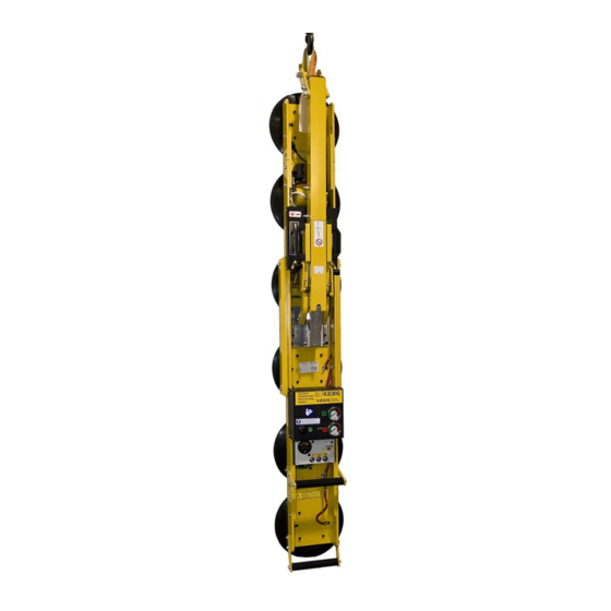
- Page 1 LEAK TEST PROCEDURE MRTALPCH611LDC – REMOTE READY LIFTERS W/ 3 BUTTON CONTROL APPLICABLE TO LIFTERS WITH SERIAL NUMBERS GREATER THAN # 20100742 TESTING AND MAINTENANCE MUST BE DONE BY A QUALIFIED PERSON KEEP FOR FUTURE REFERENCE TST-019 MRTALPCH CHANNEL – Rev. 2016-310...
- Page 2 TST-019 MRTALPCH CHANNEL – Rev. 2016-310...
- Page 3 SYMPTOMS OF VACUUM LEAK Severe leakage is evidenced by a lifter’s inability to draw full vacuum while attached to a clean, smooth, nonporous surface. In such cases, the vacuum pump will run continuously and the vacuum level shown on the vacuum gauges will be less than 16" Hg [-54 kPa], the red zone of the vacuum gauge.
- Page 4 If needed, test equipment is available from Wood’s Powr-Grip Co. To find out what is available, contact a WPG Technical Sales Representative for additional information. A set of screwdrivers may also be needed if the valve enclosure or pump cover needs to be removed.
-
Page 5: Preliminary Test
PRELIMINARY TEST This test determines whether leakage is located in the vacuum generating system or the pad system. This test should be performed if, during the overall test, the lifter’s vacuum gauges indicated a leak sufficient to warrant repair. Note: The following assumes that you have access to suitable plugs, a ball valve with vacuum gauge, and additional hose and adapter fittings for connecting the ball valve to the lifter’s vacuum lines and fittings. - Page 6 4) Remove the 1/4" o.d. hose ( ) from one of the filters ( ), that connects the filter to the pad line. Using an additional piece of 1/4" o.d. hose, connect the end of the ball valve with the vacuum gauge to the filter.
- Page 7 VACUUM GENERATING SYSTEM TEST Note: The following assumes that you have access to suitable plugs, a ball valve with vacuum gauge, and additional hose and adapter fittings for connecting the ball valve to the lifter’s vacuum lines and fittings. Note: If you are testing only one of the two circuits, the lifter will need to be attached to a clean, smooth surface for the remaining section to seal to during testing.
- Page 8 4) Remove the ball valve from the solenoid. Using a piece of 1/4" O.D. hose, cap off the end of the hose to create a fitting plug, as shown in the picture at right. Use the capped hose to cap off the port of the solenoid that connected the filter.
- Page 9 Once the vacuum generating system is confirmed to not leak, reattach the pad lines to the filters and repeat the original vacuum test with all parts attached and the power in the off position. If the vacuum level, as shown on the lifter’s vacuum gauge(s), starts and continues to drop, this indicates that there is still a leak present in the pad system.
- Page 10 12) Begin by separating the tank line from the pump/control box assembly. Disconnect the hose ( ) from the 45° barbed fitting, connected to the pump solenoid. Attach the end of the ball valve assembly with the vacuum gauge to this hose. Using an additional piece of hose, attach the other end of the ball valve to the 45°...
- Page 11 19) If a leak existed when the valve with digital vacuum switch, shown in , was tested, there is no FIGURE 9 convenient way to isolate the vacuum switch from the valve. In this case, since the digital vacuum switch is not prone to leak, the likely cause is the solenoid or an attached fitting.
- Page 12 If, during the test, the pump cycles, the indication is that the vacuum switch or the hose connections between the solenoid and the vacuum switch are the cause of the leak. Note, if the pump does begin to run, it will not shut off with the ball valve closed.
- Page 13 30) If, in step 14, the indication was that the hose connection to the vacuum tanks leak, proceed as follows. The hose runs from the solenoid valve and through the slot to the outer surface of the channel, where it is split with a Y-fitting to provide a connection to each vacuum tank;...
- Page 14 If the vacuum level of the ball valve’s vacuum gauge now holds steady and does not drop, the indication is that the leak to the vacuum tanks has been repaired. Once all identified leaks have been repaired, proceed to System Confirmation. ...
- Page 15 39) Disconnect the two hoses, one red and one green, from the Y-fitting that connect to the vacuum tanks, taking care to not damage the fitting barbs. Examine the barbs of the Y-fitting to determine if there are any large nicks in the barbs that could allow a hose to leak.
- Page 16 44) Close the ball valve (turn handle perpendicular to the valve), switch the power to off observe the vacuum gauge of the ball valve. If the vacuum level, as shown on the ball valve’s vacuum gauge, starts and continues to drop, the indication is that the hose to the tank connection ) leaks.
- Page 17 PAD SYSTEM TESTS Note: This section assumes it was determined that either the vacuum generating system does not leak or that any existing leaks in the vacuum generating system have been repaired up to the filter connections. Note: The following assumes that you have access to suitable plugs, a ball valve with vacuum gauge, and additional hose and adapter fittings for connecting the ball valve to the lifter’s vacuum lines and fittings.
- Page 18 6) Vacuum line sections and included fittings may be tested by moving up each line (toward the vacuum generating system) to the next fitting, removing the hose and plugging it at the fitting, or by installing the ball valve assembly (with the gauge end towards the section that the lifter’s gauge has been separated from) into the line.
- Page 19 9) After confirming that the quick connect does not leak, remove the cap from the barbed fitting. Remove the pad fitting from the hose and reattach the hose to the quick connect. Attach the end of the ball valve without the vacuum gauge to the hose of the quick connect and, using an additional piece of hose, attach the end of the ball valve with the...
- Page 20 12) Vacuum line sections and included fittings may be tested by moving up each line (toward the vacuum generating system) to the next fitting, removing the hose and plugging it at the fitting, or by installing the ball valve assembly into the pad line, which provides access to an additional vacuum gauge when needed.
- Page 21 To determine which, first check the hose. The ends should be square and straight; if needed, recut each end, reinstall the hose and repeat the test. If this does not resolve the leak, disconnect the reducing fitting and, using the hose adapters, attach the ball valve to the ¼"...
-
Page 22: System Confirmation
If the vacuum level of the lifter’s vacuum gauge starts and continues to drop, this indicates that the leak exists in either the hose to the gauge, the fitting attached to the gauge or the vacuum gauge itself. Examine the hose and gauge fitting for any indication of damage. If the attached parts do not appear damaged, replace the vacuum gauge. -
Page 23: Additional Information
For further suggestions or information, please contact our staff at: Wood’s Powr-Grip Co., Inc. 908 West Main Laurel, Montana 59044 800.548.7341 406.628.8231 406.682.8354 (fax) www.WPG.com ALL LIFTERS MUST BE TESTED AFTER MAINTENANCE SEE INSTRUCTION MANUAL TST-019 MRTALPCH CHANNEL – Rev. 2016-310 Page 21 of 20...
Need help?
Do you have a question about the MRTALPCH611LDC and is the answer not in the manual?
Questions and answers