Table of Contents
Advertisement
Quick Links
KEEP FOR FUTURE REFERENCE
INSTRUCTIONS
International Version
P.O. Box 368 – 908 West Main
Laurel, MT USA 59044
MODEL NUMBER: MR1611LDC
phone 800-548-7341
phone 406-628-8231
SERIAL NUMBER: ___________
fax 406-628-8354
(please see serial label and record number here)
MANUAL ROTATOR 2800
DC-VOLTAGE
READ ALL INSTRUCTIONS AND WARNINGS
BEFORE OPERATING THIS LIFTER
DESIGNED FOR THE MATERIALS HANDLING PROFESSIONAL
Advertisement
Table of Contents

Subscribe to Our Youtube Channel
Related Manuals for WPG MR1611LDC


Summary of Contents for WPG MR1611LDC
- Page 1 KEEP FOR FUTURE REFERENCE INSTRUCTIONS International Version P.O. Box 368 – 908 West Main Laurel, MT USA 59044 MODEL NUMBER: MR1611LDC phone 800-548-7341 phone 406-628-8231 SERIAL NUMBER: ___________ fax 406-628-8354 (please see serial label and record number here) MANUAL ROTATOR 2800...
-
Page 3: Table Of Contents
Monitoring the Low Vacuum Warning Buzzer (if applicable) ................18 Controlling the Lifter and Load ........................18 In Case of Power Failure ..........................18 ....................... 19 OTATE THE ..................20 ELEASE THE ADS FROM THE ......................21 FTER SING THE IFTER Storing the Lifter............................21 Rev 34.7/3-20 MR1611LDC: #35050... - Page 4 AINTENANCE YNAFLO Replacing the Diaphragm ...........................31 Replacing the Head Assembly ........................31 ....................32 ACUUM WITCH DJUSTMENT Vacuum Switch Function ..........................32 Conditions Requiring Readjustment ......................32 Adjustment Procedure ..........................33 REPLACEMENT PARTS LIST ..................34 LIMITED WARRANTY ....................35 Rev 34.7/3-20 MR1611LDC: #35050...
-
Page 5: Specifications
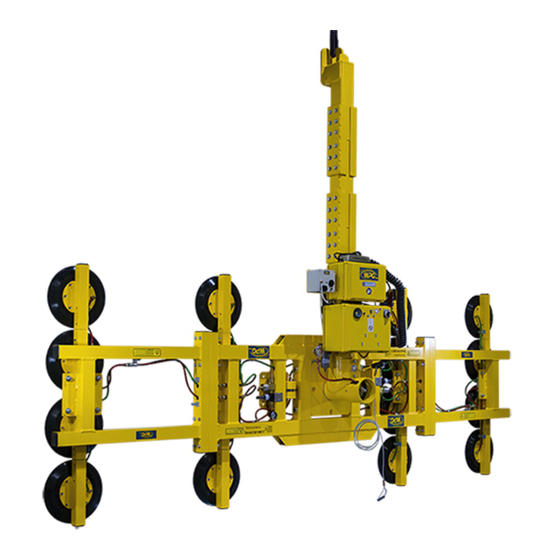
SPECIFICATIONS Model Number: MR1611LDC Description: Designed for use with a crane or other hoisting equipment, the MR1611LDC lifter employs vacuum to hold a load for lifting, and it provides manual 360° rotation movements for load manipulation. Power Source: 12 volts DC, 26 amps... -
Page 6: Warnings
(eg, releasing load) with all personnel near the lift. In addition, the operator must visually verify the status of the lifter and load prior to remote operations. Rev 34.7/3-20 MR1611LDC: #35050... -
Page 7: Operating Features
OPERATING FEATURES Note: Components featured in the following instructions for assembling, operating or maintaining the vacuum lifter are underlined on their first appearance in each section. Standard MR1611LDC shown. 1 LIFT BAR 13 VACUUM RESERVE TANK 2 LIFT BAR EXTENSION... -
Page 8: Assembly
5) Perform Operational and Load Tests for the lifter as directed in MAINTENANCE: T ESTING . If the lifter is equipped with a Remote Control System, also perform the R CHEDULE EMOTE (see MAINTENANCE). ONTROL YSTEM Rev 34.7/3-20 MR1611LDC: #35050... -
Page 9: T O Change The Pad Frame Configuration
Some configurations also require the lift bar extension (see sections to follow.) Securely position vacuum hoses to avoid damage during lifter operation. Make sure quick connectors seal completely and all vacuum hoses function correctly. Rev 34.7/3-20 MR1611LDC: #35050... -
Page 10: To Install (And Remove) The Lift Bar Extension
5) To remove the pad frame’s removable sections, reverse this 1) FEMALE END procedure. Move the release ring on the female end of the 2) MALE END quick connector away from the male end to separate the ends. Rev 34.7/3-20 MR1611LDC: #35050... -
Page 11: To Install (And Remove) Removable Pad Arms
1) Remove the 4 bolts that secure each rotating pad arm on the pad frame. 2) Rotate the arm 90° and reinstall the bolts. 3) Repeat steps 1-2 to rotate each pad arm as required for the pad frame configuration desired. Rev 34.7/3-20 MR1611LDC: #35050... -
Page 12: Intended Use
Lifters that feature concave vacuum pads can also attach to some kinds of curved loads. Since curvature affects the lifting capacity, contact WPG for help in determining the Maximum Load Capacity for a particular curved load. Rev 34.7/3-20... -
Page 13: Perating Nvironment
After the vacuum lifter has reached the end of its service life, you must dispose of the lifter in compliance with all local codes and regulatory standards that are relevant for the geographical region. Note: This lifter is equipped with a battery, which may be subject to special disposal regulations. Rev 34.7/3-20 MR1611LDC: #35050... -
Page 14: Operation
In order for a filter to function, the operator must empty the filter bowl before enough liquid accumulates to contact any portion of the filter element (see MAINTENANCE: A ILTER AINTENANCE If applicable, consult EN7731 to make sure the buzzer complies with CE Standards. Rev 34.7/3-20 MR1611LDC: #35050... -
Page 15: Confirming The Pad Frame Configuration
The Remote Control System is designed with safeguards to prevent multiple lifters from responding until a clear transmission is received. Nevertheless, radio controlled lifters should be tested to make sure that each transmitter controls only one lifter. The buttons located on the lifter function regardless of any radio transmissions in the vicinity. Rev 34.7/3-20 MR1611LDC: #35050... -
Page 16: T O Attach The Pads To A Load
2" [5 cm] of the pad frame’s center point. Occasional loading deviations are permissible, if the operator can maintain control of the load at all times the load weight is low enough to avoid damaging the lifter. Rev 34.7/3-20 MR1611LDC: #35050... -
Page 17: Sealing The Pads Against The Load
Note: If a vacuum pad has been lying against a hard object (as during shipping), it may be slightly distorted. Although initially it may be difficult to attach the pad to a load, this condition should correct itself with continued use. Rev 34.7/3-20 MR1611LDC: #35050... -
Page 18: Reading The Vacuum Gauge
Certain load materials are too rough or porous to allow the vacuum pads to form a seal that can be maintained for 5 minutes without power. However, in geographical locations where CE Standards do not apply, it may be possible to use the lifter to lift such loads. Contact Wood’s Powr-Grip for more information. Rev 34.7/3-20 MR1611LDC: #35050... -
Page 19: T O Lift And Move The Load
MAINTENANCE) and inspect the vacuum pads for damage (see MAINTENANCE: V ACUUM : Inspection). If the vacuum loss cannot be remedied immediately, perform AINTENANCE inspections and maintenance as needed to identify and correct any deficiency before resuming normal operation of the lifter. Rev 34.7/3-20 MR1611LDC: #35050... -
Page 20: Monitoring The Low Vacuum Warning Buzzer (If Applicable)
). If a power failure occurs, keep everyone clear of the suspended load until it can safely be placed on the ground or a stable support. Correct any deficiency before resuming normal operation of the lifter. Rev 34.7/3-20 MR1611LDC: #35050... -
Page 21: T O Rotate The Load
Whenever rotation is not required, keep the rotation latch engaged, to prevent accidental damage to the load and possible injury to the operator. Rev 34.7/3-20 MR1611LDC: #35050... -
Page 22: T O Release The Pads From The Load
Prior to lifting another load, perform the Every-Lift Inspection as directed in MAINTENANCE: NSPECTION CHEDULE The radio transmitter must be activated before the enable function can be used (see T : Powering TTACH THE ADS TO A Up the Lifter). Rev 34.7/3-20 MR1611LDC: #35050... -
Page 23: After Using The Lifter
Preferred temperatures for storing the battery are 32° to 70° Fahrenheit [0° to 21° Celsius]. Higher temperatures require the battery to be charged more frequently. Storage at temperatures above 100° Fahrenheit [38° Celsius] should be avoided. Rev 34.7/3-20 MR1611LDC: #35050... -
Page 24: Maintenance
• Inspect all parts of the electrical system for damage, wear or contamination that could constitute a hazard, in compliance with all local codes and regulatory standards that are relevant for the geographical region. Rev 34.7/3-20 MR1611LDC: #35050... -
Page 25: Infrequent Use
Since the low vacuum warning buzzer (if applicable) is controlled by a ASME Standard B30.20 requires the lifter to be tested to 125% of its Load Capacity. Flat Lifters are exempt from this requirement. Rev 34.7/3-20 MR1611LDC: #35050... -
Page 26: Aintenance Chedule
The battery charger must be disconnected from its AC power source in order to test the battery energy; otherwise, the energy reading on the battery gauge would not be accurate. Rev 34.7/3-20 MR1611LDC: #35050... -
Page 27: Battery Recharge
The charger is designed to automatically sense the energy level of the battery and reduce the charging rate when the battery is fully charged. Accordingly, the charger does not need to be unplugged until the lifter is going to be used again. Rev 34.7/3-20 MR1611LDC: #35050... -
Page 28: Vacuum Pad Maintenance
WARNING: Never use solvents, gasoline or other harsh chemicals to clean vacuum pad. Rev 34.7/3-20 MR1611LDC: #35050... -
Page 29: Acuum Est
If these cleaning methods are not successful, contact Wood’s Powr-Grip or an authorized dealer for assistance. Any test material used must be fully and independently supported, and capable of bearing the lifter’s weight. Do not use the lifter to lift the test material during the vacuum test. Rev 34.7/3-20 MR1611LDC: #35050... -
Page 30: Remote Control System Test
Remote Control System. If necessary, contact Wood’s Powr-Grip or an authorized dealer for assistance. Use a test material with appropriate surface characteristics (see INTENDED USE: L ) to test the “attach” HARACTERISTICS and “release” functions. Rev 34.7/3-20 MR1611LDC: #35050... -
Page 31: Air Filter Maintenance − Large
When the air filter is being used on a system, rather than with Never pressure, using the twist drain to remove liquid from the bowl is recommended. disturb the twist drain, as contaminants could lodge in the drain seal and cause a vacuum leak. Rev 34.7/3-20 MR1611LDC: #35050... -
Page 32: Replacing A Diaphragm (1)
When removing the valve plate, always take note of its orientation in the pump head (13), and install the valve plate the same way during reassembly. In all cases, the valve plate must be oriented so that its intake hole is matched with the head port that connects to the check valve. Rev 34.7/3-20 MR1611LDC: #35050... -
Page 33: Vacuum Pump Maintenance − Dynaflo Dv1032102
Depending on the product, the head assembly (3) may be rotated to an orientation different from the one shown. When removing the head assembly, always take note of its orientation and install it the same way during reassembly. Make sure that the intake and exhaust ports remain in their original positions. Rev 34.7/3-20 MR1611LDC: #35050... -
Page 34: Vacuum Switch Adjustment
, regardless of the vacuum level specified for the original Load Capacity. In addition, lifter markings should be adjusted to reflect the revised Load Capacity and the vacuum gauge should be marked to indicate the revised minimum lifting level. Rev 34.7/3-20 MR1611LDC: #35050... -
Page 35: Adjustment Procedure
In order to observe lifter functions while vacuum is decreasing, it may be necessary to create a controlled leak in the vacuum system (eg, by breaking the seal between one or more vacuum pads and the test surface). Rev 34.7/3-20 MR1611LDC: #35050... -
Page 36: Replacement Parts List
Bolt – Hex Head – 3/8-16 Thread x 5" – Grade 5 (for removable sections of pad frame) * Vacuum hose is sold by the foot (approx. 30.5 cm). Service only with identical replacement parts, available at wpg.com or through an authorized WPG dealer. Rev 34.7/3-20... -
Page 37: Limited Warranty
Contact your dealer or the Technical Service Department at Wood’s Powr-Grip Co. for assistance. Wood's Powr-Grip Co., Inc. 908 West Main St. / P.O. Box 368 Laurel, MT USA 59044 phone 800-548-7341 phone 406-628-8231 fax 406-628-8354 Rev 34.7/3-20 MR1611LDC: #35050... - Page 38 Rev 34.7/3-20 MR1611LDC: #35050...
- Page 39 Rev 34.7/3-20 MR1611LDC: #35050...
- Page 40 Rev 34.7/3-20 MR1611LDC: #35050...
- Page 41 Rev 34.7/3-20 MR1611LDC: #35050...
- Page 42 Rev 34.7/3-20 MR1611LDC: #35050...
- Page 43 Rev 34.7/3-20 MR1611LDC: #35050...
- Page 44 Rev 34.7/3-20 MR1611LDC: #35050...
- Page 45 Rev 34.7/3-20 MR1611LDC: #35050...
- Page 46 Rev 34.7/3-20 MR1611LDC: #35050...
Need help?
Do you have a question about the MR1611LDC and is the answer not in the manual?
Questions and answers