WPG MRT411LDC Operating Instructions Manual
Manual rotator/tilter, dc-voltage
Hide thumbs
Also See for MRT411LDC:
- Instructions manual (38 pages) ,
- Operating instructions manual (40 pages)
Table of Contents
Advertisement
Quick Links
KEEP FOR FUTURE REFERENCE
OPERATING
INSTRUCTIONS
INTENDED FOR USE BY SKILLED
PROFESSIONALS • READ AND
UNDERSTAND BEFORE OPERATING
MANUAL ROTATOR/TILTER,
DC-VOLTAGE
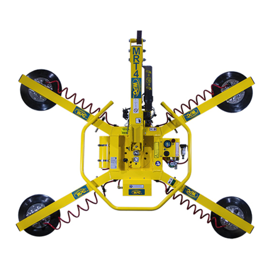
Model numbers: MRT411LDC (shown), MRT49DC,
MRT4HV11DC
Record serial number in blank space above (to locate, see serial
Rev 29.0/10-19
label on the product).
i
908 W. Main • P.O. Box 368
Laurel, MT USA 59044
800-548-7341 (phone)
406-628-8231 (phone)
406-628-8354 (fax)
www.WPG.com
MRT4-DC: #35070
Advertisement
Table of Contents

Related Manuals for WPG MRT411LDC


Summary of Contents for WPG MRT411LDC
- Page 1 INTENDED FOR USE BY SKILLED www.WPG.com PROFESSIONALS • READ AND UNDERSTAND BEFORE OPERATING MANUAL ROTATOR/TILTER, DC-VOLTAGE Model numbers: MRT411LDC (shown), MRT49DC, MRT4HV11DC Record serial number in blank space above (to locate, see serial Rev 29.0/10-19 MRT4-DC: #35070 label on the product).
- Page 2 MRT4-DC: #35070 Rev 29.0/10-19...
-
Page 3: Table Of Contents
TABLE OF CONTENTS SPECIFICATIONS ..................3 SAFETY....................5 OPERATING FEATURES................6 ASSEMBLY....................7 ..........9 HANGE THE RAME ONFIGURATION Installing/Removing Extension Arms and Repositioning Vacuum Pads ......10 Using Secondary Rotation Stops ..................11 INTENDED USE ..................12 ................12 HARACTERISTICS ................13 PERATING NVIRONMENT ................13 ISPOSAL OF THE IFTER OPERATION..................14 ................14 EFORE... - Page 4 TABLE OF CONTENTS ....................26 ESTING Lifter/Load Compatibility Test...................26 Operational Tests ......................27 Vacuum Test........................27 Rated Load Test.........................28 MAINTENANCE ..................29 ...............29 ACUUM AINTENANCE Pad-to-Load Friction Coefficient ..................29 Pad Inspection ........................29 Pad Cleaning ........................30 ..................31 ATTERY ECHARGE REPLACEMENT PARTS................32 LIMITED WARRANTY ................33 ...........33 BTAIN EPAIRS OR ARRANTY...
-
Page 5: Specifications
Design Category "B", Service Class "0" (see www.WPG.com for more information) BTH-1 1..Available with other rubber compounds for special purposes (see www.WPG.com). 2..The illustrations under “T ” on page 9 show the Pad Spread for all approved pad frame configurations. HANGE THE... - Page 6 SPECIFICATIONS Note: A standard MRT411LDC is shown. MRT4-DC: #35070 Rev 29.0/10-19...
-
Page 7: Safety
SAFETY Wear personal protective Make sure the contact surfaces of equipment that is appropriate for the load and vacuum pads are clean the load material. Follow trade before attaching the lifter (see association guidelines. “MAINTENANCE”). Do not remove or obscure safety Position the vacuum pads correctly labels. -
Page 8: Operating Features
BATTERY GAUGE 14 ROTATION RELEASE LEVER Not shown: INSTRUCTIONS CANISTER Note: The lifter model MRT411LDC is shown here. Although some of the following photos do not show this specific lifter, they all illustrate how this kind of lifter functions. MRT4-DC: #35070... -
Page 9: Assembly
ASSEMBLY Remove all lifter restraints and save them with the shipping container for future use. 2) Suspend the lifter from appropriate hoisting equipment: 2.1) Select a crane and/or hoist rated for the Maximum Load Capacity plus the Lifter Weight. Note: Any lifter use must comply with all statutory or regulatory standards for hoisting equipment in your region. - Page 10 ASSEMBLY 2.4) Use the hoisting equipment to remove the lifter from the shipping container. Avoid damaging the vacuum pads. Connect the electrical connectors (figs. 3A-B and figs. 3C-D). Assemble the pad frame for optimal load support (see “T ” on page 9). HANGE THE RAME ONFIGURATION...
-
Page 11: T O Change The Pad Frame Configuration
ASSEMBLY HANGE THE RAME ONFIGURATION Rev 29.0/10-19 MRT4-DC: #35070... -
Page 12: Installing/Removing Extension Arms And Repositioning Vacuum Pads
Dimensions show Pad Spread for a standard MRT411LDC(3) lifter (see “SPECIFICATIONS” on page 3 for other models). Caution: If the lifter is equipped with a dual vacuum system, position the vacuum pads for the 2 circuits (marked “1”... -
Page 13: Using Secondary Rotation Stops
ASSEMBLY Using Secondary Rotation Stops Align the secondary rotation stops for correct use of the pad frame in long, narrow configurations: 1) Loosen the 2 screws that secure the rotation wear plate (fig. 1A). 2) Rotate the wear plate to align with the secondary rotation stops (figs. 1B-C). 3) Tighten the screws securely (circled in fig. -
Page 14: Intended Use
2..A “single piece” of material includes curtainwall assemblies, unitized glazing systems and similar construction units. 3..Vacuum pads made from a heat-resistant rubber compound can enable you to lift loads with higher surface temperatures. Contact WPG or an authorized dealer for more information. -
Page 15: Operating Environment
1..Although lifter use may be possible at higher elevation, lifting capacity is reduced whenever the lifter is unable to attain vacuum in the green range on the vacuum gauge. Contact WPG for more information. 2..Special provisions may allow the lifter to operate outside the specified temperature range. Contact WPG for more information. Rev 29.0/10-19... -
Page 16: Operation
OPERATION EFORE SING THE IFTER Determine whether the vacuum lifter is capable of each intended task (see “SPECIFICATIONS” on page 3 and “INTENDED USE” on page 12). Then complete the following preparations: Taking Safety Precautions • Be trained in all industry Read all directions and safety rules before using and regulatory standards lifter. -
Page 17: Checking The Battery
OPERATION Checking the Battery Always check battery energy before every lift. Use the battery gauge to determine whether the battery needs to be charged (see “B ATTERY ” on page 31). Never use the lifter unless battery energy appears in the green range. ECHARGE •... -
Page 18: T O Attach The Pads To A Load
OPERATION TTACH THE ADS TO A Make sure the contact surfaces of the load and vacuum pads are clean (see “Pad Cleaning” on page 30). Positioning the Lifter on the Load Center the pad frame on the load (fig. 1A). Make sure all vacuum pads will fit on the load and will be loaded evenly (fig. -
Page 19: Sealing The Pads On The Load
1..Although a vacuum pad may become distorted during shipping or storage, this condition should correct itself with continued use. 2..If the lifter is used above the maximum Operating Elevation (see “SPECIFICATIONS” on page 3), it may not be able to maintain sufficient vacuum for lifting. Contact WPG for more information. Rev 29.0/10-19... -
Page 20: T O Lift And Move The Load
OPERATION IFT AND OVE THE Lift bar must be vertical to lift load. Interpreting the Warning Light and Optional Warning Buzzer When the vacuum Never lift load unless warning devices turn off, because lifter is ready to lift this could result in load release and personal injury. the Maximum Load Capacity, the vacuum pump and the low vacuum warning light turn off temporarily, to conserve battery energy. -
Page 21: Controlling The Lifter And Load
OPERATION Controlling the Lifter and Load When the lifter is ready, use the hoisting equipment to raise the lifter and load as needed. Use the control handle (circled in fig. 1A) to keep the lifter and load in the required position. Once there is enough clearance, you may move the load as required. -
Page 22: T O Rotate The Load
OPERATION OTATE THE Make sure the load has enough Make sure load is positioned correctly on clearance to rotate without lifter (as previously directed). contacting anyone or anything. Never disengage rotation and tilt latches at 2) Use the control handle (circled the same time, because this could result in load damage or personal injury. -
Page 23: T O Tilt The Load
OPERATION ILT THE Make sure the load has enough Make sure load is positioned correctly on clearance to tilt without lifter (as previously directed). contacting anyone or anything. Never disengage rotation and tilt latches at 2) Use the control handle (circled the same time, because this could result in load damage or personal injury. - Page 24 OPERATION A load with overhang may force you to release the control handle as the load approaches the flat position. In this case, use hand cups (circled in fig. 1A) or other appropriate means to control the load. MRT4-DC: #35070 Rev 29.0/10-19...
-
Page 25: T O Release The Pads From The Load
OPERATION ELEASE THE ADS FROM THE Make sure load is at rest and fully supported before releasing vacuum pads. 1) Press the lever to release the latch and push the valve handle inward (fig. 1A) to the “release” position ( ). Do not move lifter until pads release completely, because such movement could result in load damage or personal injury. - Page 26 OPERATION !!–CE–!! To prevent the lifter from tipping over on relatively horizontal surfaces, place the vacuum pads facedown on a clean, smooth, flat surface. Then lower the lift bar and place a support under the lift point. 2) Charge the battery completely and repeat every 6 months (see “B ”...
-
Page 27: Inspections And Tests
2..The Periodic Inspection is also required whenever the lifter has been out of service for 1 year or more. Keep a written record of all Periodic Inspections. If necessary, return the lifter to WPG or an authorized dealer for repair (see “LIMITED WARRANTY” on page 33). -
Page 28: Testing
12" Hg [-41 kPa] for 5 minutes. If not, lifting this load requires additional precautions (eg, a load sling). Contact WPG for more information. 8) Lower the load after 5 minutes or before the vacuum level diminishes to 12" Hg [-41 kPa]. -
Page 29: Operational Tests
1..The load surface should have either a flat surface or no more curvature than the lifter is designed for, if any. 2..Move the valve handle to the “release” position (power off) before reconnecting the battery. 3..For more information, search for your lifter’s Model Number at www.WPG.com and select the “Troubleshooting” link on the product page. Rev 29.0/10-19... -
Page 30: Rated Load Test
7) Prepare a written report of the test and keep it on file. 1..An equivalent simulation may also be used. Contact WPG for more information. 2..A “qualified person” has successfully demonstrated the ability to solve problems relating to the subject matter and work, either by possessing a recognized degree in an applicable field or a certificate of professional standing, or by possessing extensive knowledge, training and experience. -
Page 31: Maintenance
MAINTENANCE Notes: Refer to SERVICE MANUAL #36110 when applicable. See final section for wiring diagrams. ACUUM AINTENANCE Pad-to-Load Friction Coefficient The friction coefficient represents the lifter's ability to resist load slippage. Maximum Load Capacity is based on a friction coefficient of 1, as determined by testing of clean, new, standard rubber vacuum pads on clean, dry, regular glass. -
Page 32: Pad Cleaning
4) Allow the pad to dry completely before using the lifter. 1..A brush with bristles that do not harm rubber can help remove contaminates clinging to sealing edges. If these cleaning methods are not successful, contact WPG or an authorized dealer for assistance. MRT4-DC: #35070... -
Page 33: Battery Recharge
MAINTENANCE ATTERY ECHARGE Charge the battery whenever the battery gauge shows reduced energy. Caution: Make sure valve handle is in “release” position ( / power off). Identify the input voltage Make sure power source has ground fault circuit marked on the battery interrupter. -
Page 34: Replacement Parts
Shoulder Bolt ‒ Socket Head ‒ 5/16" x 1/2" x 1/4-20 Thread (for mounting pads) *Length as required; vacuum hose is sold by the foot (approx. 30.5 cm). See SERVICE MANUAL #36110 for additional parts. ERVICE ONLY WITH IDENTICAL REPLACEMENT PARTS WPG.COM AVAILABLE AT OR THROUGH AN AUTHORIZED DEALER MRT4-DC: #35070 Rev 29.0/10-19... -
Page 35: Limited Warranty
Contact the WPG Technical Service Department. When factory service is required, ship the complete product – prepaid – along with your name, address and phone number to the street address listed at the bottom of this page. WPG may be reached by phone or fax numbers listed below. - Page 36 MRT4-DC: #35070 Rev 29.0/10-19...
- Page 37 Rev 29.0/10-19 MRT4-DC: #35070...
- Page 38 MRT4-DC: #35070 Rev 29.0/10-19...
Need help?
Do you have a question about the MRT411LDC and is the answer not in the manual?
Questions and answers