Table of Contents
Advertisement
Quick Links
KEEP FOR FUTURE REFERENCE
INSTRUCTIONS
International Version
P .O. Box 368 – 908 W est M ain
MODEL NUMBERS: MRTARC8HV11DC,
Laurel, M T USA 59044
MRTARC811LDC
phone 800-548-7341
phone 406-628-8231
SERIAL NUMBER: ___________
fax 406-628-8354
(please see serial label and record number here)
QUADRA-TILT ROTATOR
DC-VOLTAGE, HIGH-FLOW, WITH PENDANT
R EAD ALL I NSTRUCTI ONS AND W AR NI NGS
BEFOR E OPER ATI NG THI S LI FTER
DESIGNED FOR THE MATERIALS HANDLING PROFESSIONAL
Advertisement
Table of Contents

Related Manuals for WPG MRTARC8HV11DC


Summary of Contents for WPG MRTARC8HV11DC
- Page 1 KEEP FOR FUTURE REFERENCE INSTRUCTIONS International Version P .O. Box 368 – 908 W est M ain MODEL NUMBERS: MRTARC8HV11DC, Laurel, M T USA 59044 MRTARC811LDC phone 800-548-7341 phone 406-628-8231 SERIAL NUMBER: ___________ fax 406-628-8354 (please see serial label and record number here)
-
Page 3: Table Of Contents
TABLE OF CONTENTS SPECIFICATIONS ......................3 WARNINGS ........................4 OPERATING FEATURES ....................5 ASSEMBLY ........................7 ........................ 7 ET UP THE IFTER ................8 HANGE THE RAME ONFIGURATION To Connect/Disconnect Vacuum Hoses ......................9 To Reposition (or Remove) Movable Pad Mounts ..................10 To Install/Remove Extension Arms ...................... - Page 4 MAINTENANCE ......................25 ......................25 NSPECTION CHEDULE Every-Lift Inspection ..........................25 Frequent Inspection ...........................25 Periodic Inspection .............................25 Infrequent Use............................26 ........................26 ESTING CHEDULE Operational Tests ............................26 Load Test ..............................26 ......................27 AINTENANCE CHEDULE ......................... 27 ATTERY ......................... 28 ATTERY ECHARGE ...................... 29 ACUUM AINTENANCE Friction Coefficient .............................29...
-
Page 5: Specifications
INTENDED USE. ISPOSAL OF THE IFTER ASME Standard BTH-1: Design Category "B", Service Class "0" (see www.wpg.com for more information) !!–CE–!! Note: This symbol appears in the INSTRUCTIONS manual only when requirements of a CE Standard are... -
Page 6: Warnings
WARNINGS Powr-Grip is pleased to offer the most reliable vacuum lifters available. Despite the high degree of security provided by this product, certain precautions must be observed to protect the operator and others. Alw ays wear personal protective equipment that is appropriate for the material being handled. Follow trade association guidelines. -
Page 7: Operating Features
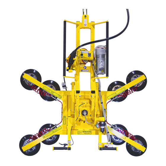
OPERATING FEATURES Note: Components featured in the following instructions for assembling, operating or maintaining the vacuum lifter are underlined on their first appearance in each section. Standard MRTARC811LDC shown with 3-SCFM [85 liters/minute] vacuum generating system and movable control pendant. 1 LIFT SPOOL 9 VACUUM GAUGE 18 VACUUM LIFT LIGHT... - Page 8 1 RADIO RECEIVER 2 RADIO TRANSMITTER 3 STROBE LIGHT 4 VACUUM LIFT LIGHT 5 LOW VACUUM WARNING BUZZER 6 ENABLE BUTTON 7 APPLY BUTTON 8 RELEASE BUTTON OPTIONAL REMOTE CONTROL SYSTEM 1 TRANSMISSION INDICATOR LIGHT 2 TRANSMITTER POWER/ENABLE BUTTON 3 RELEASE BUTTONS 4 APPLY BUTTONS 5 EMERGENCY TRANSMITTER DISCONNECT OPTIONAL RADIO TRANSMITTER...
-
Page 9: Assembly
ASSEMBLY ET UP THE IFTER 1) Open the shipping container and remove all materials for restraining or protecting the vacuum lifter. Save the container for use whenever the lifter is transported. 2) Suspend the lifter from a crane as follows: Select hoisting equipment (crane and hoist, when applicable) rated to carry the maximum load weight plus the lifter weight (see SPECIFICATIONS: Maximum Load Capacity and Lifter Weight). -
Page 10: T O Change The Pad Frame Configuration
HANGE THE RAME ONFIGURATION The lifter offers a variety of pad frame configurations to accommodate different load dimensions and weights (see SPECIFICATIONS: Pad Spread and Load Capacity). The following illustrations show several possible configurations. Select a configuration to provide optimal support across the load surface and to minimize load overhang (see OPERATION: B EFORE SING THE... -
Page 11: To Connect/Disconnect Vacuum Hoses
Configurations are created by installing or removing the pad frame’s extension arms, by repositioning or removing the movable pad mounts, and by connecting or disconnecting the vacuum hoses to certain vacuum pads. Always assemble the pad frame in a symmetrical arrangement, to keep the lifter balanced (see illustrations). -
Page 12: To Reposition (Or Remove) Movable Pad Mounts
To Reposition (or Remove) Movable Pad Mounts 1) Remove the cotterless hitch pin from one movable pad mount. 2) Move the pad mount to the desired position on the pad frame and align the holes for the cotterless hitch pin in the pad mount with the corresponding holes in the pad frame. 3) Secure the pad mount by pushing the cotterless hitch pin through the holes until the retaining ball emerges on the far side of the pad mount. -
Page 13: Intended Use
INTENDED USE HARACTERISTICS W AR NI NG: This lifter is NOT intended for lifting hazardous m aterials, such as explosives or radioactive substances. The operator must verify that the lifter is intended to handle each load, in accordance with the following requirements: •... -
Page 14: Perating Nvironment
Conversely, allowable thickness increases as load weight decreases. In addition, an operator may be able to manually counteract the tendency of unstable loads to tilt out of the upright position, provided that the operator maintains control of the load at all times (see OPERATION: T : About the Tilt Linkage and T ). -
Page 15: Disposal Of The Lifter
ISPOSAL OF THE IFTER After the vacuum lifter has reached the end of its service life, you must dispose of the lifter in compliance with all local codes and regulatory standards that are relevant for the geographical region. Note: This lifter is equipped with a battery, which may be subject to special disposal regulations. Rev 5.2/9-16 MRTARC8-DC: #35076RC... -
Page 16: Operation
OPERATION EFORE SING THE IFTER The operator must determine whether the lifter is capable of performing each intended task, in INSTRUCTIONS accordance with the SPECIFICATIONS and INTENDED USE sections of this manual. In addition, all of the following preparations must be completed prior to lifting any load. Taking Safety Precautions The operator must be trained in all relevant industry and regulatory standards for the operation of the vacuum lifter in its geographical location (eg, ASME B30.20 in the USA). -
Page 17: Confirming The Pad Frame Configuration
the Maximum Alarm Volume is 103 dBA, ambient noise must not exceed 88 dBA under any circumstances. Furthermore, if ambient noise measures 88 dBA, the alarm volume must be set to maximum and the operator must remain within 2 ft [60 cm] of the warning buzzer, in order for it to be effective. -
Page 18: T O Apply The Pads To A Load
PPLY THE ADS TO A Powering up the Lifter Place the lifter's power switch in the “on” ( ) position. The blue power light remains illuminated while the lifter is powered up. Keep the power switch in the “on” position while lifting a load. -
Page 19: Sealing The Pads Against The Load
Sealing the Pads against the Load The apply/release switch is located on the movable control pendant. The movable control pendant allows the vacuum controls to be moved away from the lifter, so that the operator can control airflow at a distance equal to the length of the extension cord. W AR NI NG: Do not disconnect control pendant during lifter operation. -
Page 20: Vacuum Level On Optimal Surfaces
Vacuum Level on Optimal Surfaces When the lifter is attached to clean, smooth, nonporous load surfaces, it should be able to maintain a vacuum level in the green range on the vacuum gauge, except when used at high elevations (see SPECIFICATIONS: Operating Elevation). If not, make sure the vacuum switch is adjusted correctly (see MAINTENANCE: V ). -
Page 21: T O Lift And Move The Load
IFT AND OVE THE About the Tilt Linkage W AR NI NG: M ak e sure load is positioned correctly on lifter; unbalanced loads m ay tilt unexpectedly. The lifter’s tilt linkage is designed to automatically hold a balanced load in either the upright or the flat position. -
Page 22: Load Capacity And The Lift Light
Load Capacity and the Lift Light A lifter’s Load Capacity is rated at a vacuum level of 16" Hg [-54 kPa] (see SPECIFICATIONS). After the lifter has attained this level, the vacuum pumps turn off automatically, to conserve battery energy. At the same time, the green vacuum lift light turns on, to indicate that the lifter is ready to lift the maximum load weight. -
Page 23: Controlling The Lifter And Load
W AR NI NG: Stay clear of any suspended load w hile alarm is sounding. Discontinue lifter use until the cause of the vacuum loss can be determined. Using the lifter on contaminated, rough or porous surfaces may result in a vacuum loss, due to leakage between the vacuum pads and the load. -
Page 24: T O Tilt The Load
ILT THE W AR NI NG: Alw ays keep hands and fingers aw ay from bars of tilt linkage. Remember that the load requires more vertical space when tilted to the upright position, as well as more horizontal space when tilted to the flat position. -
Page 25: T O Release The Pads From The Load
ELEASE THE ADS FROM THE W AR NI NG: Load m ust be fully supported before releasing vacuum pads. Make sure the load is at rest and fully supported. Then turn the apply/release switch on the movable control pendant to the “release” ( ) position (counter-clockwise) to force air into the vacuum pads, quickly breaking the vacuum seal. -
Page 26: After Using The Lifter
FTER SING THE IFTER Leave the apply/release switch in the neutral position and place the power switch in the “off” position ( ). The blue indicator light shuts off when the operator powers down the lifter. If the lifter is equipped with a Remote Control System, also turn off the radio transmitter. CAUTI ON: Do not set the lifter against any surfaces w hich could soil or dam age the vacuum pads. -
Page 27: Maintenance
MAINTENANCE W AR NI NG: Alw ays m ake sure battery is disconnected before servicing lifter. INSTRUCTIONS Note: One or more wiring diagrams are provided in the final section of this manual for reference when servicing the lifter or trouble-shooting a deficiency. NSPECTION CHEDULE Perform inspections routinely, according to the following frequency schedule:... -
Page 28: Infrequent Use
CAUTI ON: Be sure to use appropriate cleaning m ethods for each type of electrical com ponent, as specified by codes and standards. I m proper cleaning can dam age com ponents. • Keep a written record of all Periodic Inspections. If any deficiency is detected during the inspection, correct it before using the lifter. -
Page 29: Aintenance Chedule
vacuum switch, consult the V discussion for inspection, testing and ACUUM WITCH DJUSTMENT adjustment procedures. AINTENANCE CHEDULE INSTRUCTIONS Unless specified elsewhere in this manual, the lifter does not require maintenance on a routine basis. Instead, maintenance must be performed whenever a deficiency is indicated by routine inspections or tests. -
Page 30: Battery Recharge
ATTERY ECHARGE CAUTI ON: Charge battery only w hile lifter’s pow er sw itch is in the “off” ( position. Operating the lifter when the battery charger is connected to an AC power source could result in permanent damage to the charger. Only use a battery charger supplied by or approved by Wood's Powr-Grip;... -
Page 31: Vacuum Pad Maintenance
ACUUM AINTENANCE Friction Coefficient The friction coefficient represents the lifter's ability to resist load slippage when the load is oriented in any position except horizontal. If the contact surfaces of either the load or the vacuum pads are not clean, dry and in good condition, slippage is more likely to occur. The Load Capacity of most Powr-Grip lifters is based on a friction coefficient of 1 (only Flat Lifters are exempt from this requirement). -
Page 32: Vacuum Test
W AR NI NG: Never use unauthorized rubber cleaners or conditioners to clean vacuum pad. To prevent liquid from contaminating the vacuum system during cleaning, cover the suction hole in the recess for the filter screen or make sure the pad faces downward. Use a clean sponge or lint-free cloth to apply an authorized cleanser and wipe the pad face clean. -
Page 33: Remote Control System Test
EMOTE ONTROL YSTEM If the lifter is equipped with a Remote Control System, perform this test in the environment where the lifter is normally employed. Use the radio transmitter to activate each of the remote functions. Vary the location and distance of the transmitter in relation to the lifter, to ensure that transmissions are effective in a variety of circumstances. -
Page 34: Air Filter Maintenance − Large
− L ILTER AINTENANCE ARGE (for 4.4 oz [130 ml] bowl size filters) Filter Function and Conditions Requiring Service An air filter prevents solid particles and liquid from contaminating components in the vacuum system. CAUTI ON: Exam ine air filter regularly and em pty w hen necessary. Liquid must not contact any portion of the filter element;... -
Page 35: Vacuum Pump Maintenance - Thomas 2907Cdc22/12
― T 2907CDC22/12 ACUUM AINTENANCE HOMAS W AR NI NG: Before proceeding w ith any m aintenance, disconnect pow er source. If the vacuum pump takes too long to attain full vacuum, it may require maintenance (see OPERATING FEATURES for location of pump). Replace the diaphragms, valve flappers or head gaskets as necessary to obtain acceptable pump performance (see REPLACEMENT PARTS LIST). -
Page 36: Vacuum Pump Maintenance − Dynaflo Dv1032102
− D DV1032102 ACUUM AINTENANCE YNAFLO W AR NI NG: Before proceeding w ith any m aintenance, disconnect pow er source. If the vacuum pump takes too long to attain full vacuum, it may require maintenance. Replace the diaphragm, gasket/flap valves or (when preferable) the entire head assembly (see REPLACEMENT PARTS LIST), as necessary to obtain acceptable pump performance. -
Page 37: Vacuum Switch Adjustment
ACUUM WITCH DJUSTMENT Vacuum Switch Function A vacuum switch controls the vacuum pump and the vacuum lift light (see OPERATING FEATURES for location of vacuum switch). When the power switch located on the lifter is in the “on” position ( ), activating the apply function engages the vacuum pump, which evacuates the vacuum pads. -
Page 38: Adjustment Procedure
m aintain a higher vacuum level Otherwise, the lifter would not maintain sufficient vacuum to lift the maximum load weight. Adjustment Procedure W AR NI NG: Load capacity decreases w henever vacuum sw itch is adjusted to m aintain low er vacuum level. 1) Using a 1/4"... -
Page 39: Replacement Parts List
Vacuum Pad - Model G3370 / 11" [28 cm] Diameter - Lipped (for MRTARC811LDC) 49605T Vacuum Pad - Model HV11 / 10" [25 cm] Diameter - Lipped (for MRTARC8HV11DC) 49150 End Plug - 2 1/2" x 2 1/2" x 1/4" [63.5 mm x 63.5 mm x 6.4 mm] Tubing Size Rev 5.2/9-16... - Page 40 Stock No. Description Qty. 49122 End Plug - 2" x 2" x 1/4" [50.8 mm x 50.8 mm x 6.4 mm] Tubing Size 29353 Pad Cover 20270 1/4" [6.4 mm] Open-End Wrench (for adjusting vacuum switch) 16132 Filter Element Kit (for 4.4 oz [130 ml] bowl size air filter) 16057 Quick Connector - 1/8 FNPS - Male End 16056...
-
Page 41: Limited Warranty
LIMITED WARRANTY Powr-Grip products are carefully constructed, thoroughly inspected at various stages of production, and individually tested. They are warranted to be free from defects in workmanship and materials for a period of one year from the date of purchase. If a problem develops during the warranty period, follow the instructions hereafter to obtain warranty service. - Page 42 Rev 5.2/9-16 MRTARC8-DC: #35076RC...
- Page 43 Rev 5.2/9-16 MRTARC8-DC: #35076RC...
- Page 44 Rev 5.2/9-16 MRTARC8-DC: #35076RC...
- Page 45 Rev 5.2/9-16 MRTARC8-DC: #35076RC...
- Page 46 Rev 5.2/9-16 MRTARC8-DC: #35076RC...
Need help?
Do you have a question about the MRTARC8HV11DC and is the answer not in the manual?
Questions and answers