Table of Contents
Advertisement
Quick Links
KEEP FOR FUTURE REFERENCE
OPERATING
INSTRUCTIONS
INTENDED FOR USE BY SKILLED
PROFESSIONALS • READ AND
UNDERSTAND BEFORE OPERATING
QUADRA-TILT
ROTATOR, DC-VOLTAGE
WITH INTELLI-GRIP®
TECHNOLOGY
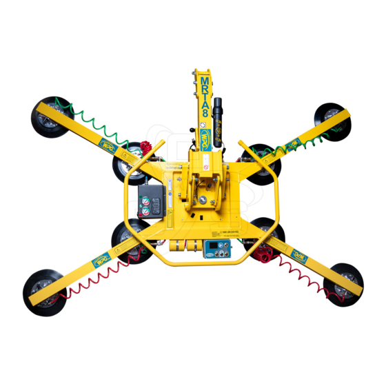
Model numbers: MRTA811LDC3 (shown),
MRTA810TDC3, MRTA810CDC3O
Record serial number in blank space above (to locate, see serial
Rev 5.0/2-21
label on the product).
1
908 W. Main • P.O. Box 368
Laurel, MT USA 59044
800-548-7341 (phone)
406-628-8231 (phone)
406-628-8354 (fax)
www.WPG.com
MRTA8-DC3: #35121AUS
Advertisement
Table of Contents

Related Manuals for WPG MRTA811LDC3


Summary of Contents for WPG MRTA811LDC3
- Page 1 INTENDED FOR USE BY SKILLED www.WPG.com PROFESSIONALS • READ AND UNDERSTAND BEFORE OPERATING QUADRA-TILT ROTATOR, DC-VOLTAGE WITH INTELLI-GRIP® TECHNOLOGY Model numbers: MRTA811LDC3 (shown), MRTA810TDC3, MRTA810CDC3O Record serial number in blank space above (to locate, see serial Rev 5.0/2-21 MRTA8-DC3: #35121AUS label on the product).
- Page 2 MRTA8-DC3: #35121AUS Rev 5.0/2-21...
-
Page 3: Table Of Contents
TABLE OF CONTENTS SPECIFICATIONS ..................3 SAFETY....................5 OPERATING FEATURES................6 ASSEMBLY....................7 ..........9 HANGE THE RAME ONFIGURATION Installing or Removing Extension Arms and Repositioning Vacuum Pads ......11 Using Secondary Rotation Stops ..................12 Connecting/Disconnecting Vacuum Hoses ...............13 INTENDED USE ..................14 ................14 HARACTERISTICS ................15 PERATING NVIRONMENT ................15 ISPOSAL OF THE... - Page 4 TABLE OF CONTENTS ................28 FTER SING THE IFTER Transporting the Lifter ......................28 Storing the Lifter .......................28 INSPECTIONS AND TESTS..............30 ................30 NSPECTION CHEDULE ....................31 ESTING Lifter/Load Compatibility Test...................31 Operational Tests ......................32 Vacuum Test........................32 Rated Load Test.........................33 MAINTENANCE ..................34 ...............34 ACUUM AINTENANCE Pad-to-Load Friction Coefficient ..................34 Pad Inspection ........................34 Pad Cleaning ........................35...
-
Page 5: Specifications
Compliant with AS 4991. Note: Each circuit of the Dual Vacuum System complies with the capacity Design Standard requirements of this Standard. 1..Available with other rubber compounds for special purposes (see www.wpg.com). 2..Standard with replaceable sealing rings for rough or textured surfaces (see “REPLACEMENT PARTS”). - Page 6 SPECIFICATIONS Note: A standard MRTA811LDC3 is shown. MRTA8-DC3: #35121AUS Rev 5.0/2-21...
-
Page 7: Safety
SAFETY Wear personal protective Make sure the contact surfaces of equipment that is appropriate for the load and vacuum pad are clean the load material. Follow trade before attaching the lifter (see association guidelines. “MAINTENANCE”). Do not remove or obscure safety Position the vacuum pads correctly labels. -
Page 8: Operating Features
14 BATTERY (hidden) 15 ROTATION RELEASE LEVER LIFT BAR Note: A standard MRTA811LDC3 is shown. Although some of the following photos do not show this specific lifter, they all illustrate how this kind of lifter functions. For information about specific parts, see “REPLACEMENT PARTS”... -
Page 9: Assembly
ASSEMBLY Remove all shipping materials and save them with the shipping container for future use. 2) Suspend the lifter from appropriate hoisting equipment: 2.1) Select a crane and/or hoist rated for the Maximum Load Capacity plus the Lifter Weight. Note: Any lifter use must comply with all statutory or regulatory standards for hoisting equipment in your region. - Page 10 ASSEMBLY 2.4) Use the hoisting equipment to remove the lifter from the shipping container. Avoid damaging the vacuum pads. Connect the electrical connectors (figs. 3A-B and figs. 3C-D). Install the 9-volt battery for the notification buzzer as directed in “N OTIFICATION UZZER ATTERY...
-
Page 11: T O Change The Pad Frame Configuration
ASSEMBLY HANGE THE RAME ONFIGURATION Rev 5.0/2-21 MRTA8-DC3: #35121AUS... - Page 12 Various pad frame configurations enable the lifter to match different load dimensions and weights. The illustrations on the preceding page show all approved configurations. Pad Spread and Maximum Load Capacities are listed for a standard MRTA811LDC3 lifter (see “SPECIFICATIONS” for other models).
-
Page 13: Installing Or Removing Extension Arms And Repositioning Vacuum Pads
ASSEMBLY Installing or Removing Extension Arms and Repositioning Vacuum Pads 1) Remove the cotterless hitch pin that secures the movable pad mount to the pad frame (fig. 1A). Remove the vacuum pad from the pad frame (fig. 2A) and, if necessary, disconnect the vacuum hose. -
Page 14: Using Secondary Rotation Stops
ASSEMBLY Using Secondary Rotation Stops Align the secondary rotation stops for correct use of the pad frame in long, narrow configurations. MRTA8-DC3: #35121AUS Rev 5.0/2-21... -
Page 15: Connecting/Disconnecting Vacuum Hoses
ASSEMBLY Connecting/Disconnecting Vacuum Hoses To connect a vacuum hose, push the male and female ends of Make sure quick the quick connector together until they lock (fig. 1A). connectors seal completely and all vacuum To disconnect a vacuum hose, move the release ring on the hoses function correctly (see female end until the quick connector separates (fig. -
Page 16: Intended Use
2..A “single piece” of material includes curtainwall assemblies, unitized glazing systems and similar construction units. 3..Vacuum pads made from a heat-resistant rubber compound can enable you to lift loads with higher surface temperatures. Contact WPG or an authorized dealer for more information. -
Page 17: Operating Environment
1..Although lifter use may be possible at higher elevations, lifting capacity is reduced whenever the lifter is unable to attain vacuum in the green range on the vacuum gauge. Contact WPG for more information. 2..Special provisions may allow the lifter to operate outside the specified temperature range. Contact WPG for more information. Rev 5.0/2-21... -
Page 18: Operation
OPERATION EFORE SING THE IFTER Determine whether the vacuum lifter is capable of each intended task (see “SPECIFICATIONS” “INTENDED USE”). Then complete the following preparations: Taking Safety Precautions • Be trained in all industry and regulatory Read all directions and safety standards for lifter operation in your region. -
Page 19: Performing Inspections And Tests
OPERATION Performing Inspections and Tests • Follow the “I ” “T ”. NSPECTION CHEDULE ESTING • Service the 2 air filters whenever a bowl contains Examine air filters regularly liquid or other contaminates, or an element and service when needed. appears dirty (see “A ”... -
Page 20: T O Attach The Pads To A Load
OPERATION TTACH THE ADS TO A Make sure the contact surfaces of the load and vacuum pads are clean (see “Pad Cleaning”). Positioning the Lifter on the Load Center the pad frame on the load (fig. 1A). If the lifter has tilt locks, disengage them first. -
Page 21: Powering Up The Lifter
OPERATION Powering up the Lifter Press the lifter's power button ( — fig. 1A). The vacuum pump will run for a few seconds, ® as a normal function of the Intelli-Grip self- diagnostics. The lifter automatically tests the 9-volt battery for the notification buzzer each time the lifter is powered up. - Page 22 1..The gauge face colors do not correspond with the circuit colors. 2..If the lifter is used above the maximum Operating Elevation (see “SPECIFICATIONS”), it may not be able to maintain sufficient vacuum for lifting. Contact WPG for more information. MRTA8-DC3: #35121AUS...
-
Page 23: Ift And Ove The Oad
OPERATION IFT AND OVE THE About the Tilt Linkage The tilt linkage minimizes operator effort and Unbalanced loads may tilt automatically holds a balanced load in either unexpectedly during lifter operation. the upright or the flat position. However, an Make sure load is positioned unbalanced load may tilt unexpectedly, correctly on lifter. -
Page 24: Engaging Or Disengaging Tilt Locks
OPERATION Engaging or Disengaging Tilt Locks Tilt locks prevent tilt movement due to wind loads or other unexpected forces. They should be used whenever the operator cannot maintain control of the load directly (eg, when using the lifter to install glass in multi-story buildings). -
Page 25: Interpreting The Lift Light
OPERATION Interpreting the Lift Light When the vacuum lifter is ready to lift Never lift load unless lift the Maximum Load Capacity, the light is illuminated, vacuum lift light turns on automatically and because premature lifting could the vacuum pump turns off temporarily, to result in load release and personal injury. -
Page 26: Controlling The Lifter And Load
OPERATION Controlling the Lifter and Load When the lifter is ready, use the hoisting equipment to raise the lifter and load as needed. Use a control handle (circled in fig. 1A) to keep the lifter and load in the required position. Once there is enough clearance, you may move the load as required. -
Page 27: T O Rotate The Load
OPERATION OTATE THE Make sure load is positioned correctly on lifter (as previously directed). Make sure the load has enough clearance to rotate without contacting anyone or anything. 2) Use the control handle (circled in fig. 2A) to keep the load under control at all times. -
Page 28: T O Tilt The Load
OPERATION ILT THE Keep hands and fingers away from tilt linkage. Make sure the load has enough clearance to tilt without contacting anyone or anything. 2) Use the control handle (circled in fig. 2A) to keep the load under control at all times. 3) Make sure the tilt locks (circled in fig. -
Page 29: T O Release The Pads From The Load
OPERATION ELEASE THE ADS FROM THE Make sure load is at rest and fully supported before releasing vacuum pads. 1) Hold the “function” button ( — fig. 1A) and the “release” button ( — fig. 1A). If the vacuum seal does not break, follow the directions on the LCD screen. -
Page 30: After Using The Lifter
OPERATION FTER SING THE IFTER Press the power button ( — fig. 1A) and the “function” button ( — fig. 1A) to power down the vacuum lifter. 2) Charge the battery after each workday as needed (see “12-V ATTERY ”). ECHARGE 3) Use the hoisting equipment to lower the lifter gently onto a stable support. - Page 31 OPERATION Disconnect the electrical connectors (figs. 3A-B and figs. 3C-E) to prevent battery discharge. 4) Store the lifter in a clean, dry location. Store the battery between 32° and 70° F [0° — 21° C]. Avoid storage above 100° F [38° C]. Rev 5.0/2-21 MRTA8-DC3: #35121AUS...
-
Page 32: Inspections And Tests
2..The Periodic Inspection is also required whenever the lifter has been out of service for 1 year or more. Keep a written record of all Periodic Inspections. If necessary, return the lifter to WPG or an authorized dealer for repair (see “LIMITED... -
Page 33: Testing
12" Hg [-41 kPa] for 5 minutes. If not, lifting this load requires additional precautions (eg, a load sling). Contact WPG for more information. 8) Lower the load after 5 minutes or before the vacuum level diminishes to 12" Hg [-41 kPa]. -
Page 34: Operational Tests
2..During this time, the LCD screen displays “WARNING: Is load attached?”, the notification buzzer chirps and the strobe light flashes. 3..For more information, search for your lifter’s Model Number on www.wpg.com and select the “Troubleshooting” link on the product page. -
Page 35: Rated Load Test
7) Prepare a written report of the test and keep it on file. 1..An equivalent simulation may also be used. Contact WPG for more information. 2..A “qualified person” has successfully demonstrated the ability to solve problems relating to the subject matter and work, either by possessing a recognized degree in an applicable field or a certificate of professional standing, or by possessing extensive knowledge, training and experience. -
Page 36: Maintenance
MAINTENANCE Note: Refer to SERVICE MANUAL #36106 when applicable. ACUUM AINTENANCE Pad-to-Load Friction Coefficient The friction coefficient represents the lifter's ability to resist load slippage. The Maximum Load Capacity is based on a friction coefficient of 1, as determined by testing of clean, new, standard rubber vacuum pads on clean, dry, regular glass. -
Page 37: Pad Cleaning
4) Allow each pad to dry completely before using the lifter. 1..A brush with bristles that do not harm rubber can help remove contaminates clinging to sealing edges. If these cleaning methods are not successful, contact WPG or an authorized dealer for assistance. Rev 5.0/2-21... -
Page 38: T O Replace Sealing Ring In Vpfs10T Pads
MAINTENANCE VPFS10T P EPLACE EALING ING IN If the lifter has VPFS10T vacuum pads, replace sealing rings (#49724RT or #49724TT) as follows: 1) Remove the old sealing ring (fig. 1A). Note: Make sure the entire vacuum pad is clean, including the mounting groove. -
Page 39: 12-Volt Battery Recharge
MAINTENANCE 12-V ATTERY ECHARGE Charge the battery whenever the battery gauge shows reduced energy. Caution: Make sure the lifter is powered down. Identify the input voltage marked on the battery Make sure power source has charger and plug it in to an appropriate power ground fault circuit interrupter. -
Page 40: Notification Buzzer Battery Replacement
MAINTENANCE OTIFICATION UZZER ATTERY EPLACEMENT 1) Power down the lifter. 2) Release the buzzer battery holder by pressing inward and sideward in the direction marked on the holder. Slide the battery tray out (fig. 3A). 4) Install a new 9-volt battery according to the polarity markings. 5) Slide the battery tray back into position. -
Page 41: Ntelli Rip Iagnostic Odes
MAINTENANCE ® D NTELLI IAGNOSTIC ODES Refer to the following table when a diagnostic code appears on the LCD screen. Codes are listed in alphanumeric order. If the Explanations/Directions do not resolve the issue, contact qualified service personnel. All relevant parts are listed in “REPLACEMENT PARTS”. - Page 42 MAINTENANCE Strobe Buzzer Code On-Screen Message Light Explanations/Directions Pattern Activity continuous Once “Power Save” mode is activated, “attach” and “Control head revision lockout” (while button (none) “release” functions are prevented in connection with Code is held) C06. Service is required. occasional “EEPROM error, cell #”...
- Page 43 “Vacuum not increasing 1 chirp every V020 securely (see “Sealing the Pads on the Load” “Reading normally” 2 seconds the Vacuum Gauges”). This Code can be activated by use at high elevation. If so, contact WPG for directions. Rev 5.0/2-21 MRTA8-DC3: #35121AUS...
- Page 44 2 seconds system. See relevant topics in “ASSEMBLY,” “OPERATION” “INSPECTIONS AND TESTS”, and “MAINTENANCE”. In case of high elevation, contact WPG for directions. Once “Power Save” mode is activated, “attach” and “release” functions are prevented due to a vacuum sensor V040 “Lockout (vacuum sensor error)”...
-
Page 45: Replacement Parts
Shoulder Bolt ‒ Socket Head ‒ 5/16" x 1/2" x 1/4-20 Thread (for mounting pads) * Length as required; hose is sold by the foot (approx 30.5 cm). SERVICE MANUAL #36106 for additional parts. ERVICE ONLY WITH IDENTICAL REPLACEMENT PARTS WPG.COM AVAILABLE AT OR THROUGH AN AUTHORIZED DEALER Rev 5.0/2-21... -
Page 46: Limited Warranty
Contact the WPG Technical Service Department. When factory service is required, ship the complete product – prepaid – along with your name, address and phone number to the street address listed at the bottom of this page. WPG may be reached by phone or fax numbers listed below. - Page 47 Rev 5.0/2-21 MRTA8-DC3: #35121AUS...
- Page 48 MRTA8-DC3: #35121AUS Rev 5.0/2-21...
Need help?
Do you have a question about the MRTA811LDC3 and is the answer not in the manual?
Questions and answers