WPG MRT49DC Instructions Manual
Manual rotator / tilter dc-voltage
Hide thumbs
Also See for MRT49DC:
- Operating instructions manual (38 pages) ,
- Operating instructions manual (40 pages)
Table of Contents
Advertisement
Quick Links
KEEP FOR FUTURE REFERENCE
INSTRUCTIONS
International Version
MODEL NUMBERS: MRT49DC,
P.O. Box 368 – 908 West Main
Laurel, MT USA 59044
MRT4HV11DC, MRT411LDC
phone 800-548-7341
SERIAL NUMBER: ___________
phone 406-628-8231
fax 406-628-8354
(please see serial label and record number here)
MANUAL ROTATOR / TILTER
DC-VOLTAGE
READ ALL INSTRUCTIONS AND WARNINGS
BEFORE OPERATING THIS LIFTER
DESIGNED FOR THE MATERIALS HANDLING PROFESSIONAL
Advertisement
Table of Contents

Subscribe to Our Youtube Channel
Related Manuals for WPG MRT49DC


Summary of Contents for WPG MRT49DC
- Page 1 KEEP FOR FUTURE REFERENCE INSTRUCTIONS International Version MODEL NUMBERS: MRT49DC, P.O. Box 368 – 908 West Main Laurel, MT USA 59044 MRT4HV11DC, MRT411LDC phone 800-548-7341 SERIAL NUMBER: ___________ phone 406-628-8231 fax 406-628-8354 (please see serial label and record number here)
-
Page 3: Table Of Contents
TABLE OF CONTENTS SPECIFICATIONS ......................3 WARNINGS ........................4 OPERATING FEATURES ....................5 ASSEMBLY ........................6 ........................ 6 ET UP THE IFTER ................6 HANGE THE RAME ONFIGURATION Basic Configuration ............................7 Linear Configuration ............................. 7 Extended Configuration ..........................7 Secondary Rotation Stops .......................... - Page 4 MAINTENANCE ......................18 ......................18 NSPECTION CHEDULE Every-Lift Inspection ..........................18 Frequent Inspection ...........................18 Periodic Inspection .............................18 Infrequent Use............................19 ........................19 ESTING CHEDULE Operational Tests ............................19 Load Test ..............................19 ......................20 AINTENANCE CHEDULE ......................... 20 ATTERY ......................... 21 ATTERY ECHARGE ...................... 21 ACUUM AINTENANCE Friction Coefficient .............................21...
-
Page 5: Specifications
D after its service life, see INTENDED USE. ISPOSAL OF THE IFTER ASME Standard BTH-1: Design Category "B", Service Class "0" (see www.wpg.com for more information) INSTRUCTIONS different !!‒CE‒!! Note: This symbol appears in the manual only when requirements of a CE Standard are from requirements of other standards that also apply to this vacuum lifter. -
Page 6: Warnings
WARNINGS Powr-Grip is pleased to offer the most reliable vacuum lifters available. Despite the high degree of security provided by this product, certain precautions must be observed to protect the operator and others. Always wear personal protective equipment that is appropriate for the material being handled. Follow trade association guidelines. -
Page 7: Operating Features
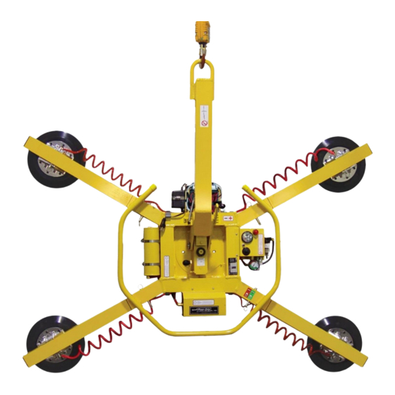
OPERATING FEATURES Note: Components featured in the following instructions for assembling, operating or maintaining the vacuum lifter are underlined on their first appearance in each section. Standard MRT411LDC shown. 1 LIFT BAIL 7 AIR FILTER 15 CONTROL HANDLE 2 INSTRUCTIONS CANISTER 8 BATTERY GAUGE 16 VACUUM RESERVE TANK 3 BATTERY... -
Page 8: Assembly
ASSEMBLY ET UP THE IFTER 1) Open the shipping container and remove all materials for restraining or protecting the vacuum lifter. Save the container for use whenever the lifter is transported. 2) Suspend the lifter from a crane as follows: Select hoisting equipment (crane and hoist, when applicable) rated to carry the maximum load weight plus the lifter weight (see SPECIFICATIONS: Maximum Load Capacity and Lifter Weight). -
Page 9: Basic Configuration
WARNING: Make sure all vacuum hoses are coiled or routed so they cannot become entangled, kinked or punctured during rotation or tilt. MRT411LDC shown; see SPECIFICATIONS for other models’ Pad Spread. Basic Configuration This configuration provides a small, rectangular pad spread. Remove all 4 extension arms and mount the vacuum pads directly to the arm sockets on the main pad frame. -
Page 10: Intended Use
INTENDED USE HARACTERISTICS WARNING: This lifter is NOT intended for lifting hazardous materials, such as explosives or radioactive substances. The operator must verify that the lifter is intended to handle each load, in accordance with the following requirements: • The load must not exceed the maximum allowable weight specified under Load Capacity (see SPECIFICATIONS). -
Page 11: Perating Nvironment
PERATING NVIRONMENT The operator must determine whether the lifter is intended to be used in each work environment, in accordance with the following restrictions: WARNING: Never use lifter in dangerous environments. • This lifter is not intended for use in any environment that is inherently dangerous to the operator or likely to compromise the lifter's ability to function. -
Page 12: Operation
OPERATION EFORE SING THE IFTER The operator must determine whether the lifter is capable of performing each intended task, in INSTRUCTIONS accordance with the SPECIFICATIONS and INTENDED USE sections of this manual. In addition, all of the following preparations must be completed prior to lifting any load. Taking Safety Precautions The operator must be trained in all relevant industry and regulatory standards for the operation of the vacuum lifter in its geographical location (eg, ASME B30.20 in the USA). -
Page 13: T O Apply The Pads To A Load
the alarm volume must exceed ambient noise by In order to be considered clearly audible, at least 15 dBA at the operator position. Since the Maximum Alarm Volume is 103 dBA, ambient noise must not exceed 88 dBA under any circumstances. Furthermore, if ambient noise measures 88 dBA, the alarm volume must be set to maximum and the operator must remain within 2 ft [60 cm] of the warning buzzer, in order for it to be effective. -
Page 14: Reading The Vacuum Gauge
Reading the Vacuum Gauge green The vacuum gauge indicates the current vacuum level in the lifter’s vacuum system. The range indicates vacuum levels sufficient for lifting the maximum load weight, whereas the range indicates vacuum levels that are sufficient for lifting the maximum load weight. The gauge needle should show a sudden surge in vacuum as the vacuum pads seal against the load. -
Page 15: Positioning The Lift Bar
IFT AND OVE THE Positioning the Lift Bar WARNING: Lift bar must be oriented vertically to lift load. Never lift the load from a flat position with the lift bar latched parallel to the load. Always disengage the tilt latch (see T ILT THE follow) and raise the lift bar to a vertical orientation before attempting to lift. -
Page 16: Monitoring The Low Vacuum Warning Buzzer (If Applicable)
Monitoring the Low Vacuum Warning Buzzer (if applicable) If the lifter is equipped with a low vacuum warning buzzer, an alarm sounds until the lifter attains sufficient vacuum to lift the maximum load weight (see SPECIFICATIONS: Load Capacity). After the lifter has attained this vacuum level, the alarm stops sounding, to indicate that the lifter is ready to lift the load. -
Page 17: T O Rotate The Load Edgewise
OTATE THE DGEWISE WARNING: Never disengage both the rotation latch and the tilt latch at the same time. This lifter is not designed for rotation and tilt functions to be used at the same time. Disengaging the rotation and tilt latches simultaneously could cause uncontrolled and unpredictable load movement, potentially resulting in load damage or injury to the operator. -
Page 18: T O Tilt The Load
ILT THE WARNING: Never disengage both the rotation latch and the tilt latch at the same time. This lifter is not designed for rotation and tilt functions to be used at the same time. Disengaging the rotation and tilt latches simultaneously could cause uncontrolled and unpredictable load movement, potentially resulting in load damage or injury to the operator. -
Page 19: Fter Sing The Ifter
FTER SING THE IFTER Leave the valve handle in the “release” ( ) position (power off). CAUTION: Do not set the lifter against any surfaces which could soil or damage the vacuum pads. Use the hoisting equipment to gently lower the lifter onto a stable support; then detach the hoisting equipment hook from the lift bail. -
Page 20: Maintenance
MAINTENANCE WARNING: Always make sure battery is disconnected before servicing lifter. INSTRUCTIONS Note: One or more wiring diagrams are provided in the final section of this manual for reference when servicing the lifter or trouble-shooting a deficiency. NSPECTION CHEDULE Perform inspections routinely, according to the following frequency schedule: Every-Lift Inspection •... -
Page 21: Infrequent Use
• Keep a written record of all Periodic Inspections. If any deficiency is detected during the inspection, correct it before using the lifter. If necessary, return the lifter to Powr-Grip or an authorized dealer for repair (see LIMITED WARRANTY). Infrequent Use each time If a lifter is used less than 1 day in a 2-week period, perform the Periodic Inspection before using the lifter... -
Page 22: Maintenance Schedule
AINTENANCE CHEDULE INSTRUCTIONS Unless specified elsewhere in this manual, the lifter does not require maintenance on a routine basis. Instead, maintenance must be performed whenever a deficiency is indicated by routine inspections or tests. Any maintenance warranted must be performed before resuming normal operation of the lifter. ATTERY The lifter is equipped with a battery gauge to help the operator evaluate whether the battery has adequate energy for lifting. -
Page 23: Battery Recharge
ATTERY ECHARGE Charge the battery whenever the battery gauge indicates diminished energy (see B ATTERY CAUTION: Make sure valve handle is in “release” position (power OFF). preceding). Identify the input voltage marked on the battery charger, and plug it in to an appropriate power source. -
Page 24: Inspection
follow). Over time, the rubber in a pad may experience hardening or leaching of chemicals, resulting in stiffness or surface glaze. Pads that exhibit wear, stiffness or glaze must be replaced. In addition, all pads should be replaced on a regular basis, preferably after no more than 2 years, to ensure that the friction coefficient is not compromised. -
Page 25: Vacuum Test
ACUUM Test the vacuum system for leakage routinely, as directed in the preceding I NSPECTION ESTING CHEDULES 1) Clean the face of each vacuum pad as previously directed (see V ACUUM AINTENANCE Cleaning). 2) Apply the lifter to a clean, smooth, nonporous surface. The surface should be flat or possess no more curvature than the lifter is designed for (if any). -
Page 26: Air Filter Maintenance − Small
− S ILTER AINTENANCE MALL (for 1 oz [30 ml] bowl size filters) Filter Function and Conditions Requiring Service An air filter prevents solid particles and liquid from contaminating components in the vacuum system. CAUTION: Examine air filter regularly and empty when necessary. Liquid must not contact any portion of the filter element;... -
Page 27: Vacuum Pump Maintenance − Dynaflo Dv1032102
− D DV1032102 ACUUM AINTENANCE YNAFLO WARNING: Before proceeding with any maintenance, disconnect power source. If the vacuum pump takes too long to attain full vacuum, it may require maintenance. Replace the diaphragm, gasket/flap valves or (when preferable) the entire head assembly (see REPLACEMENT PARTS LIST), as necessary to obtain acceptable pump performance. -
Page 28: Vacuum Pump Maintenance − Thomas 107Cdc20
− T 107CDC20 ACUUM AINTENANCE HOMAS WARNING: Before proceeding with any maintenance, disconnect power source. If the vacuum pump (14) takes too long to attain full vacuum, it may require maintenance. Replace the diaphragm, valve flappers or head gasket as necessary to obtain acceptable pump performance (see REPLACEMENT PARTS LIST). -
Page 29: Vacuum Switch Adjustment
ACUUM WITCH DJUSTMENT Vacuum Switch Function A vacuum switch controls the low vacuum warning light and the vacuum pump (see OPERATING FEATURES for location of vacuum switch): The valve handle activates the warning light and the pump, which evacuates the vacuum pads. After the lifter attains a vacuum level sufficient for lifting the maximum load weight (hereafter, “minimum lifting level”), the vacuum switch automatically turns off the pump and the warning light. -
Page 30: Adjustment Procedure
Adjustment Procedure WARNING: Lifting capacity decreases whenever vacuum switch is adjusted to maintain lower vacuum level. 1) Using a 1/4" open-end wrench (as provided), turn the adjustment screw about 1/6th turn at a time (approximately one flat of the screw head). lower clockwise To maintain a... -
Page 31: Replacement Parts List
Cotterless Hitch Pin ‒ 1/2" x 4" [13 mm x 102 mm] 10900 Shoulder Bolt ‒ Socket Head ‒ 5/16" x 1/2" x 1/4-20 Thread (for mounting pads) SERVICE ONLY WITH IDENTICAL REPLACEMENT PARTS, AVAILABLE AT WPG.COM OR THROUGH AN AUTHORIZED WPG DEALER Rev 27.0/7-17 MRT4-DC: #35070... -
Page 32: Limited Warranty
LIMITED WARRANTY Powr-Grip products are carefully constructed, thoroughly inspected at various stages of production, and individually tested. They are warranted to be free from defects in workmanship and materials for a period of one year from the date of purchase. If a problem develops during the warranty period, follow the instructions hereafter to obtain warranty service. - Page 33 Rev 27.0/7-17 MRT4-DC: #35070...
- Page 34 Rev 27.0/7-17 MRT4-DC: #35070...
- Page 35 Rev 27.0/7-17 MRT4-DC: #35070...
- Page 36 Rev 27.0/7-17 MRT4-DC: #35070...
- Page 37 Rev 27.0/7-17 MRT4-DC: #35070...
- Page 38 Rev 27.0/7-17 MRT4-DC: #35070...
Need help?
Do you have a question about the MRT49DC and is the answer not in the manual?
Questions and answers