Table of Contents
Advertisement
Quick Links
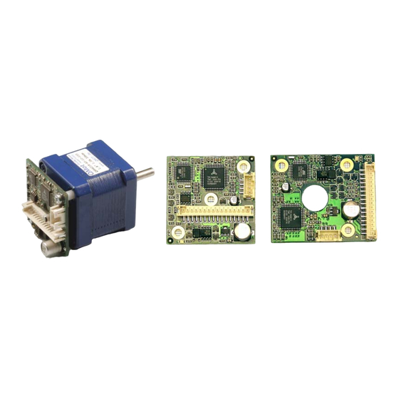
PANdrive PD013-42
and
TMCM-013 and TMCM-013-LA
Manual
STEPPER motor controller/driver module
1A RMS (1.5A peak) / 30V
with RS485 and step-/ direction interface
Trinamic Motion Control GmbH & Co. KG
Sternstraße 67
D – 20357 Hamburg, Germany
Phone +49-40-51 48 06 – 0
FAX: +49-40-51 48 06 – 60
http://www.trinamic.com
INFO@TRINAMIC.COM
Advertisement
Table of Contents

Related Manuals for Trinamic PANdrive PD013-42


Summary of Contents for Trinamic PANdrive PD013-42
- Page 1 Manual STEPPER motor controller/driver module 1A RMS (1.5A peak) / 30V with RS485 and step-/ direction interface Trinamic Motion Control GmbH & Co. KG Sternstraße 67 D – 20357 Hamburg, Germany Phone +49-40-51 48 06 – 0 FAX: +49-40-51 48 06 – 60 http://www.trinamic.com...
-
Page 2: Table Of Contents
Changes required for DC motor mode operation............... 25 6.6.2 Parameterizing with RS485 ....................26 6.6.3 Motion Control........................26 Revision History ..........................27 Documentation Revision ......................27 Firmware Revision ........................27 Copyright © 2005, TRINAMIC Motion Control GmbH & Co. KG... - Page 3 Table 6.10: Adjustment of Microstep Resolution................... 20 Table 6.11: Chopper mode 3 switching velocities................. 22 Table 6.12: External signals and motor reactions ................. 22 Table 7.1: Documentation Revisions..................... 27 Table 7.2: Firmware Revisions......................27 Copyright © 2005, TRINAMIC Motion Control GmbH & Co. KG...
-
Page 4: Features
59 x 42 x 42 PD3-013-42 PANdrive 0.49Nm 69 x 42 x 42 TMCM-013 Electronics module 14 x 42 x 42 TMCM-013-LA Electronics module 14 x 42 x 50 Table 1.1: Order codes Copyright © 2005, TRINAMIC Motion Control GmbH & Co. KG... -
Page 5: Life Support Policy
Specifications subject to change without notice. Copyright © 2005, TRINAMIC Motion Control GmbH & Co. KG... -
Page 6: Outer Description
RS485 - RS485 remote control access -, TTL input OA1, OA2 Connections for motor coil A OB1, OB2 Connections for motor coil B Table 3.1: Pinning of TMCM-013 and TMCM-013-LA Copyright © 2005, TRINAMIC Motion Control GmbH & Co. KG... -
Page 7: Dimensions
12.5mm 5.4 mm 44.6 mm 50.0 mm Figure 3.3: Dimensions for TMCM-013LA 3.3 Connectors Both connectors are crimp connectors series B4B-PH-SM3-TB, PH-connector. Motor: 4 pin connector Control: 16 pin connector Copyright © 2005, TRINAMIC Motion Control GmbH & Co. KG... -
Page 8: Operational Ratings
Input voltage on GPI 0 ... 5 Output voltage on GPO and Alert (open collector) Output current on GPO and Alert -150 (open collector) Environment temperature °C operation Table 4.1: Operational Ratings Copyright © 2005, TRINAMIC Motion Control GmbH & Co. KG... -
Page 9: Step, Direction And Disable Inputs
E: Emitter Step Figure 4.1: Step, Direction and Disable Inputs Examples: = 5V undefined OPTON OPTOFF = 0V 1.5V 4.0V STEP = 20V undefined OPTON OPTOFF = 0V 16.5V 19.0V STEP Copyright © 2005, TRINAMIC Motion Control GmbH & Co. KG... -
Page 10: Getting Started
For most dynamic operation choose mode 0, or the combined modes 3 and 4 which use mode 1 or 2 for slow movements and switch to mode 0 at a defined velocity. Copyright © 2005, TRINAMIC Motion Control GmbH & Co. KG... -
Page 11: Motor Velocity
12 V 466 mH 2300 mH 24 V 1720 mH 18 V 350 mA 1150 mH 12 V 666 mH Table 5.1: Maximum Supply Voltage regarding Motor Current and Inductivity Copyright © 2005, TRINAMIC Motion Control GmbH & Co. KG... -
Page 12: Connecting Motor And Power Supply
In larger systems a zener diode circuitry might be required, when motors are operated at high velocities. Copyright © 2005, TRINAMIC Motion Control GmbH & Co. KG... -
Page 13: Connections For Step/Direction-Mode
The maximum step frequency is 350 kHz (limited by the opto couplers). 5.5 Connections for RS485 Interface The RS485-mode allows for configuration of motor parameters as well as remote control of the motor. Copyright © 2005, TRINAMIC Motion Control GmbH & Co. KG... -
Page 14: Interface Installation
TMCM-013 Manual (V1.17 / August 30th, 2006) 5.5.1 Interface installation To connect the module to a PC a RS485 interface is required, for example Trinamic’s new USB-2-485 or any other RS485 adapter, like the standard RS232 to RS485-converters. Input A has to be connected to pin 15 of the TMCM-013 and Input B to pin 16. -
Page 15: Functional Description
A Reset to factory default is possible. Default address byte is “A” and default baud rate is 9600 baud. This mode can only be used with an appropriate RS485 interface. Commands are sent with a terminal program, refer 5.5. Copyright © 2005, TRINAMIC Motion Control GmbH & Co. KG... -
Page 16: Rs485 Commands
1. Set chopper mode to SPI Mode: AM 0 ⇒ ENTER 2. Read out the actual mode Am ⇒ ENTER 3. Change Microstep resolution ¼ of max. resolution AZ 2 ⇒ ENTER Copyright © 2005, TRINAMIC Motion Control GmbH & Co. KG... -
Page 17: Example For Test Move
Short circuit detected. Please check motor wiring. Table 6.3: Failure readout in SPI mode In the other two modes the failure analysis consists of only one bit: 1: short circuit or overtemperature 0: no failure Copyright © 2005, TRINAMIC Motion Control GmbH & Co. KG... -
Page 18: Stallguard (G)
The bit settings are as follows: Value Description ALARM output is inactive ALARM output is active No function ALARM is set to active when driver detects a failure Table 6.6: Alert adjustments Copyright © 2005, TRINAMIC Motion Control GmbH & Co. KG... -
Page 19: Output Setting (O)
149157 microsteps ⋅ 149157 steps steps Microstep resolution ⋅ 149157 rotations rotations ⋅ Microstep resolution Fullsteps motor For a 200 step motor at 64 microsteps, this gives rotations rotations 85815 Copyright © 2005, TRINAMIC Motion Control GmbH & Co. KG... -
Page 20: Store Parameters To Eeprom (W)
R . A higher value would lead to an COIL, MAX MOTOR excess of motor rating. The minimum supply voltage has to be above two times the nominal motor voltage. Copyright © 2005, TRINAMIC Motion Control GmbH & Co. KG... -
Page 21: Chopper Mode 1 (Pwm)
If x is in the range 0.5 to 1.0, try operating your motor and check if motor or driver gets too hot. If x is above 1.0, choose one of the other chopper modes. See also chapter 5.2.1.3 for graphical demonstration. Copyright © 2005, TRINAMIC Motion Control GmbH & Co. KG... -
Page 22: Chopper Mode 3 (Phase And Spi)
Rotate right Rotate left Increase or Direction open Direction Control Step frequency decrease of Step wired or connected connected to frequency to V Ground Table 6.12: External signals and motor reactions Copyright © 2005, TRINAMIC Motion Control GmbH & Co. KG... -
Page 23: Direction
Frequency: The maximum Step input frequency is 350 kHz, aligned to the Direction signal. The minimum logic ”0” time is 0.7 µs and the minimum logic “1” time is 2.0 µs. Function Table: Extern open wire = 5…24V Intern HIGH Copyright © 2005, TRINAMIC Motion Control GmbH & Co. KG... -
Page 24: Firmware Update
1. Choose your RS485 connection. 2. Select your Module ID (default is A). 3. Load the new firmware file (e.g. TMCM013_V1.08.hex), to download from www.trinamic.com. 4. Start the update process. At the end of the update process check your firmware version with command “AX”. -
Page 25: Reset To Factory Default
However, there are two free places for 0805 SMD resistors to be equipped directly on the module TMCM-013. To enable this mode solder resistors as follows: Attention: Do not try to make changes on the board until you are absolutely sure. Copyright © 2005, TRINAMIC Motion Control GmbH & Co. KG... -
Page 26: Parameterizing With Rs485
Change the voltage at GPI between 7…28V. The motor will accelerate and decelerate relative to the specified zero point. Additional parameters like resolutions of microsteps can be stored in the EEPROM. Copyright © 2005, TRINAMIC Motion Control GmbH & Co. KG... -
Page 27: Revision History
Full functionality (except DC-Motor) with some possibilities to expand 1.08 Bug fix, new Added chopper modes 3 and 4, modified V command, corrected RS485 options bug (always echoing of CR at earlier versions) Table 7.2: Firmware Revisions Copyright © 2005, TRINAMIC Motion Control GmbH & Co. KG...
Need help?
Do you have a question about the PANdrive PD013-42 and is the answer not in the manual?
Questions and answers